
The Inherent Flaw of All Waveform Generators
By: Chris Bake
What Is a Duty Cycle?
Duty cycle is an important concept in electronics and refers to the ratio of the duration of a signal's active state to the total period of the signal. It is often expressed as a percentage, and it can be used to control the amount of power delivered to a device. Duty cycle is an essential parameter in many electronic devices, including pulse width modulation (PWM) systems, where it determines the average power delivered to the load.
The duty cycle of a signal is determined by the width of the pulse or the duration of time the signal is active, relative to the total period of the signal. For example, if a signal has a period of 1 second and is active for 0.5 seconds, its duty cycle would be 50%. A higher duty cycle indicates that the signal is active for a longer period of time relative to the total period, and vice versa for a lower duty cycle.
When the signal is high, we call this "on time". To describe the amount of "on time" , we use the concept of duty cycle. Duty cycle is measured in percentage. The percentage duty cycle specifically describes the percentage of time a digital signal is on over an interval or period of time. This period is the inverse of the frequency of the waveform.
If a digital signal spends half of the time on and the other half off, we would say the digital signal has a duty cycle of 50% and resembles an ideal square wave. If the percentage is higher than 50%, the digital signal spends more time in the high state than the low state and vice versa if the duty cycle is less than 50%. Here is a graph that illustrates these three scenarios:
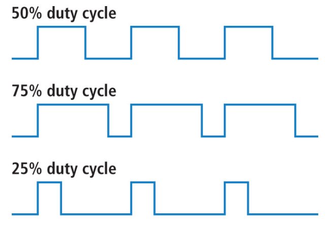
50%, 75%, and 25% Duty Cycle Examples
100% duty cycle would be the same as setting the voltage to 5 Volts (high). 0% duty cycle would be the same as grounding the signal.
Regardless of the method of Duty control, the same behavior is presented.
The Inherent Problem
Let's say that you wanted to create a certain gated pulse waveform.
The Battle Of Clocks
To gate an integral clock pulse sequence from a continuous source without distorting pulse duration and number is not a trivial task. In most cases, a simple AND gate will cause problems, see Figure 1.
Clock pulses pass through the AND gate as long as the asynchronous strobe E is high. If loss or distortion of even one pulse is critical, then the simple AND gate is unsuitable, as the first and the last pulse in the burst will often be distorted (shorter than usual pulse) due to the lack of synchronization between clock and E.
This Design Idea demonstrates a mathematical approach to synthesize an asynchronous gated circuit able to gate an accurate pulse train from a clock signal without distorting pulse duration. Such circuits are called quantizers.

Figure 1
The Adjustment Problem
- Pulse Duty indirectly affects Width/Space inversely
- Gate Duty indirectly affects Pulse Count operation
- Independent Pulse eliminates a concept of duty, and thus retains width/space parameters, and extends accordingly, the pulses and chronological gate offtime period occurring thereafter.
- Independent Gate eliminates the indirect effect to Pulse Count when you try to adjust gate offtime, but it also affects future chronology.
What is more important? True Period or Chronology? Isn't chronology only settable by the re-occurrence of consecutive periods? Does it matter, and Why? We need this answer.
Independent Width vs Spacing Control
To be continued....