
Photographic Estate Dimensional Analysis - 3D Printable Replication
As of 5-2-23, the below STLs are currently being printed and tested. It is recommended until verification of the parts is completed, that the content herein should be for information only.
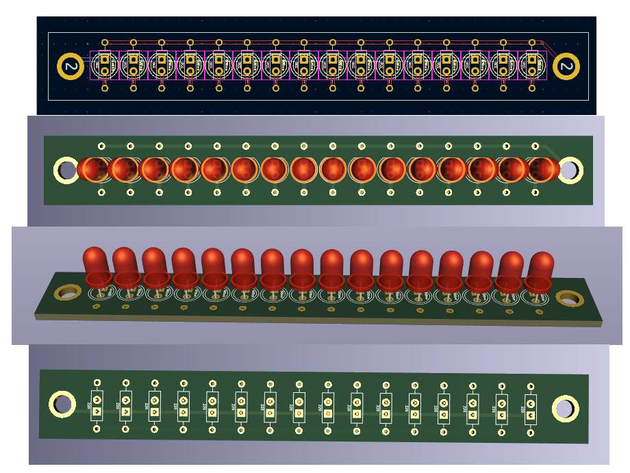
Estate photographs were used in conjunction with a pair of calipers. Screen was adjusted until a common reference point was ascertained. The reference point used was the known dimensions of the LED PCB width, being 1.00". Length was determined by laying out the number of 5mm LEDs (16-qty) in a PCB CAD software. The distance from the first to the last was exactly 4.00". When the screw terminal via holes are added, the board length becomes 4.75" long. This is what decided the length of the acrylic body.
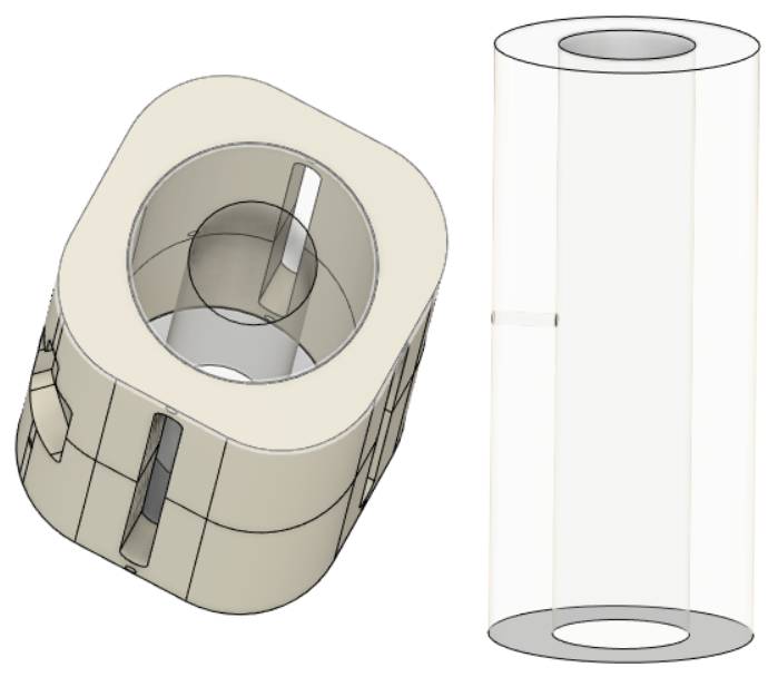
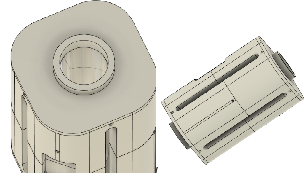
ACRYLIC PHOTON INJECTION BODY:
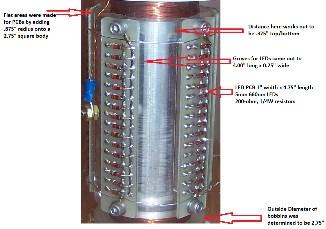
Acrylic "photon injection" diameter: 2.75" (note that flat spots were intentionally done on the 3D prints to allow for LED PCBs. It was found that a square of equal sides, 2.75" with .875" radius on each corner produced the desired outer diameter and provided 1" wide flat surfaces for PCB mounting). A 0.375" depth was chosen based off dimensions of 5mm LEDs for the grooved portion.
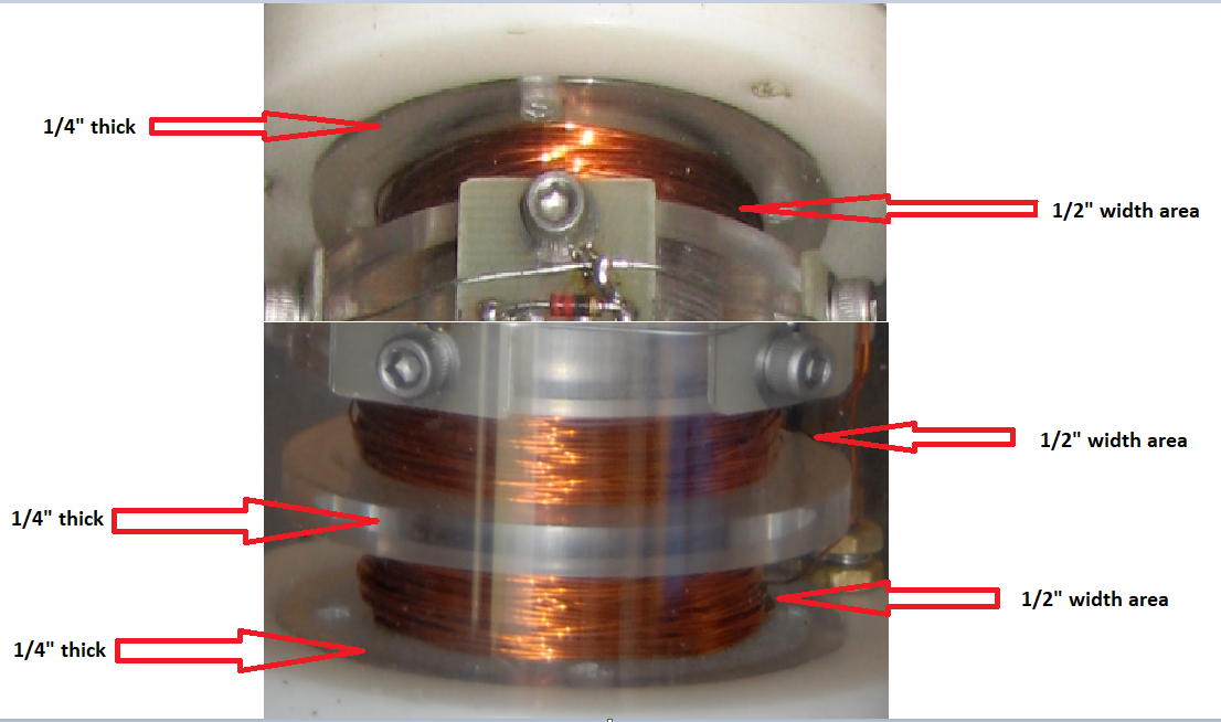
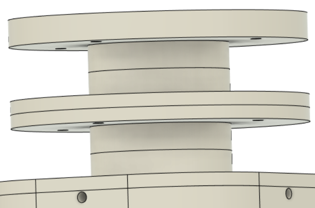
ACRYLIC BOBBINS:
Top and bottom bobbin end appear to have some type of mounting holes that appear to line up with holes on the end caps. These were determined to the closest approximate of 2.125" on centers. This was included in STL designs.
REPLICATION BREAKDOWN:
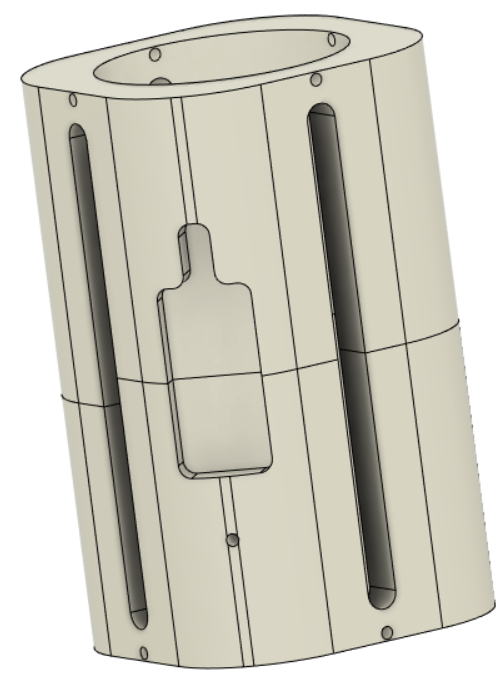
The photo injection body is meant to be printed in PLA/PETG as this shouldn't be required to be clear, as only in inner chamber has light pulsed. There are two pieces. One top and one bottom. There was intentionally a shorter section on the bottom (1a) and a longer section on the top (1b). This is functioning as a keying to avoid mistakes in assembly. These two section need to be glued at their center junction. The larger diameter seen is for a acrylic resin cast from a mast mold.

ACRYLIC LENS:
Having solid piece of acrylic machined is costly and difficult to source for only one piece. These hurdles inspired the idea of 3D printing a mold template. There is a hole provided for tapping a 10-32 screw connection into outer electrode. Once cured, the lens is inserted coaxially to the inner/outer electrode. For best results, the silicone mold and acrylic resin should be placed inside vacuum chamber to remove air bubbles during curing. Gluing is not intended for this piece.
Inner Diameter: 1.025"
Outer Diameter: 1.980"
Length is 4.50"
PHOTON BODY END PLATES:
In order to secure the acrylic lens, and provide a gluing surface for coil bobbins, two "end caps" are to be glued into place on each end of the body. This brings the total length to 4.75".
OUTER ELECTRODE:
Outer electrode is T-304 stainless steel tube. 7.00" in length, 1.00" outside diameter, 0.94" inside diameter, 0.030" wall. Grooves are cut at 90 degree displacements, measuring 4.00" long.
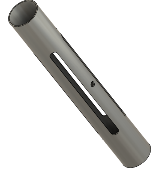
OUTER ELECTRODE STENCIL:
Being that the machining required to cut grooves in the tubing is costly, for only one piece, an stencil to go over the body for marking grooves was made. The intention was to cut the grooves with Dremel cutting wheel.
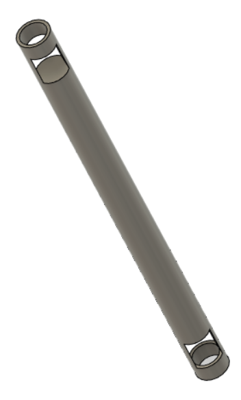
INNER ELECTRODE:
BODY TOP END BOBBIN HALF PIECE:
Glue the 0.25" thick bobbin to the top via the 1.30" surface. This will complete the top bobbin for coil.
HGG bobbin half piece .25 thick.stl

BODY BOTTOM BOBBIN HALF PIECE:
At the bottom of the body, glue a .125" thick bobbin half piece to the corresponding 1.30" diameter surface.
HGG Bobbin half piece .125 thick.stl

Next, glue another .125" thick bobbin half piece to the 2.75" surface.

Next, glue last .25" bobbin half piece the 1.30" surface.
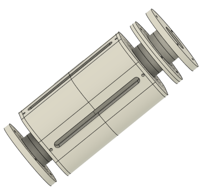
COMPLETE ASSEMBLY:
Following the steps above will yield a completed assembly.
INSERT OUTER ELECTRODE:
Press fit in the 1" outer electrode, aligning the grooves in the tube with the grooves in the plastic body.
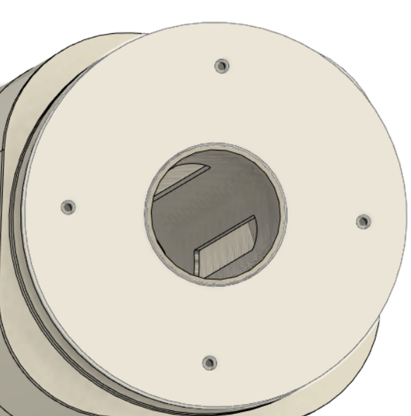
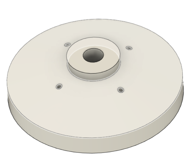
BOTTOM END CAP:
The bottom end cap has recessions on the bottom to receive wiring. Terminals are 8-32" brass screws. Inner electrode should be press fitted like shown.
Insert the inner electrode so it is coaxial to the inside of the outer electrode.

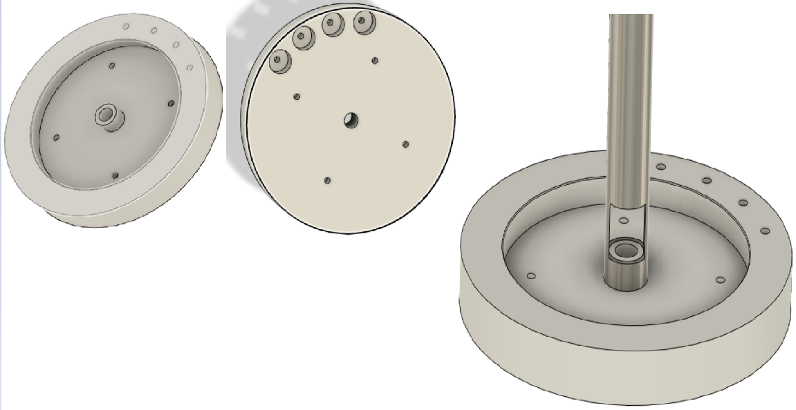
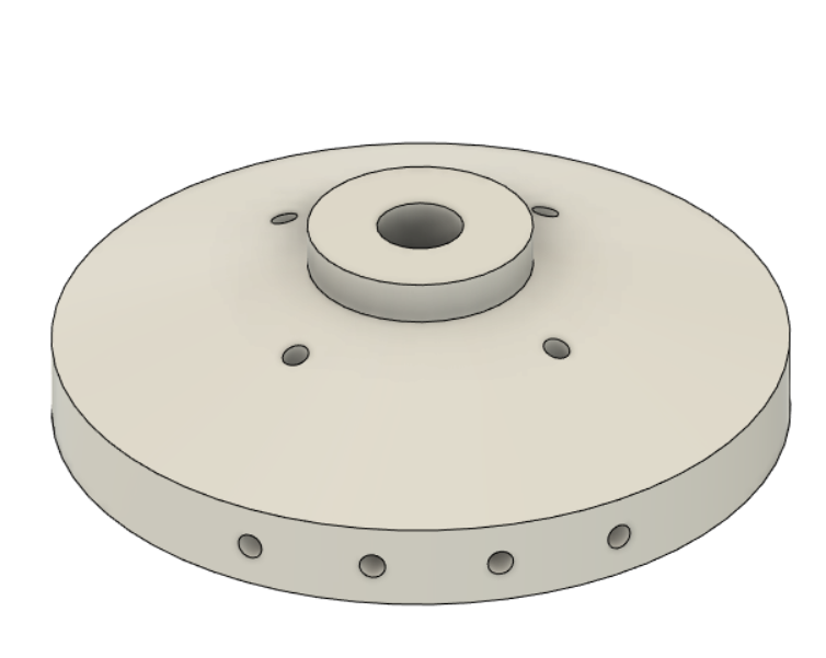
TOP END CAP:
Repeat the same step for top end cap that was done for the bottom be inserting inner electrode into middle support.
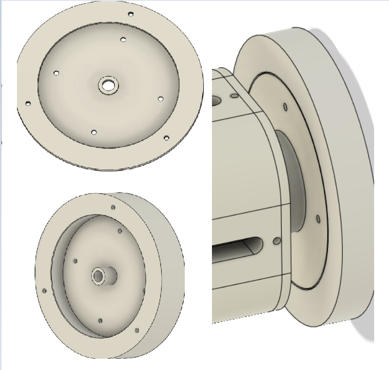
INSTALLING TOP/BOTTOM CAPS:
Top cap goes on top of the "top end cap".
Bottom cap goes onto the bottom end cap. 2.125" holes line up for securing through "bottom end cap" and bottom 0.25" wall coil bobbin. When installing this one, make sure the four holes on the side match the four holes on the inside.
COMPLETE UNIT:
This is what the entire unit should look like once completed.
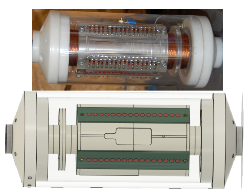
ORIGINAL HYDROGEN GAS GUN:
