
Adjustable Duty Cycle Gated Pulse Frequency
One can use a 555 with two 1N4148 diodes to allow independent control of duty cycle ON/OFF times. Each diode has a 100k 10-turn precision potentiometer placed in series to capacitor as shown below. Rotary switch for selection of different capacitor values can allow frequency range selectivity. "RA" below can be a potentiometer to allow for frequency adjustment.
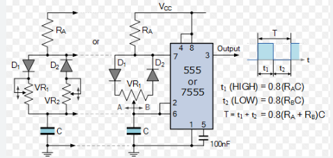
Photo from Electronic Tutorials: Electronic Tutorials (555)
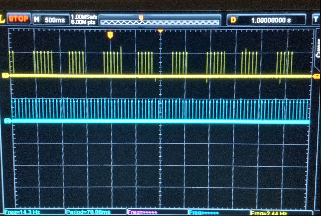
In the build below, pin 3 of 555 was also output to CD4017 decade counter stage to produce a gate. This provided clock synchronization, and only allows 5 pulses per gate ON time. Otherwise, any independent driver of CD4017 would produce clock drift and not allow a discrete number of pulse per gate ON time. Beauty of shift registers in 4017's is even though a 1mS ON time may be occurring, the whole period will be used to divide by 10. Thus maintaining a 50% gated pulse time if desired. Both the adjusted pulse train from Pin #3 and output of CD4017 (Pin #12) is put into inputs (Pin #1 and Pin #2) of a 7408 AND logic gate chip. Pin #3 on 7408 is output, which is shown in yellow below on scope. Circuit driver side isolation may be achieved with H11D1 similar to the 9XA.
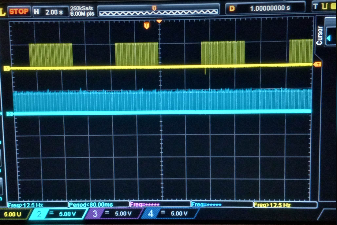
Gate can be adjusted by RA resistor to produce increase occurrences of pulse train
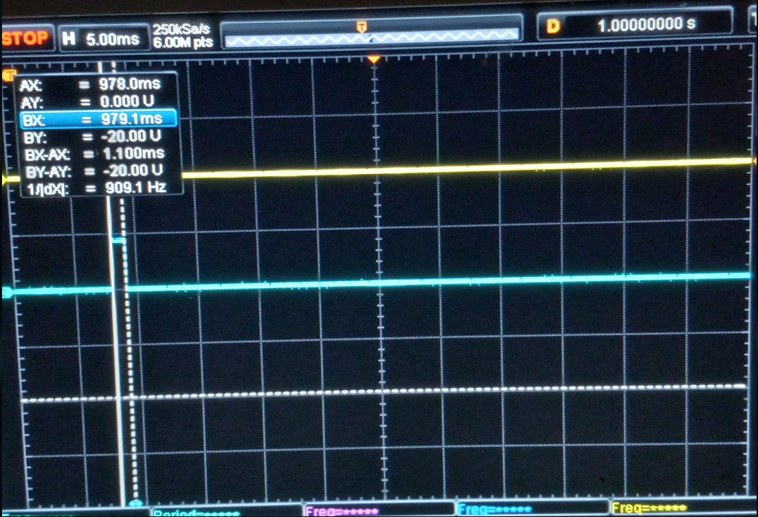
Pulse duty cycle ON time, down to lowest, measured at 1mS.
Adjustable Gated Pulse Freq Gen
This method allows pulse duty cycle control, and synchronized gate to pulse train.