
Pulse Forming Networks
Source: https://www.ga.com/capacitors/pulse-forming-networks
One of the major circuit applications of General Atomics Energy Products capacitors is that of Pulse  Forming Networks or PFNs. PFNs are usually comprised of a number of capacitors and inductors arranged so that the discharge pulses from the capacitors are spaced in time, resulting in a square or trapezoidal current pulse with a relatively flat top. Rectangular pulses are needed for various types of loads, including charged particle accelerators, microwave sources, and lasers.
A common form of PFN used in radar modulators is the Guillemin Type E network, in which the  capacitance is the same in each mesh and there is mutual inductance between adjacent coils. The squareness of the output pulse is a function of the number of meshes. The risetime is determined by the risetime of the first mesh in the network, closest to the load. The pulse width is twice the one-way transit time of the wave. If the characteristic impedance of the PFN is matched to that of the load, the energy will be almost completely dissipated in the load (no reflection), and the voltage across the load will be one-half the charge voltage of the PFN capacitors. Typically the inductor closest to the load is made larger than the other inductors. This is done to prevent overshoot. This inductor is ~30% larger than the other inductors.
| C = T / 2Z L = TZ / 2 |
| C = total capacitance µF |
| L = total inductance µH |
| T = pulse length µsec |
| Z = characteristic impedance ohms |
The nominal capacitance and inductance per mesh are simply the totals divided by the number of meshes. Adjustment of the mutual inductance between meshes and the precise values of the first and last mesh inductances are used to "tune" the network for optimum performance. Sometimes the inductors are wound on a continuous form. Optimum wave shape is typically obtained with about 15% mutual coupling between inductors in the PFN. This type of PFN is known as a Type E PFN.
Schematic showing a 4-stage Type E PFN, output switch, and load
It is possible to use multiple PFNs with switches to provide discretely adjustable pulse widths to the load, such as in the example below:
Schematic showing two PFNs with an isolating switch for variable outputs
Examples of some other types of PFNs
There are many topologies that can be used to form a PFN. Several are shown below. For a detailed discussion of PFN’s see Pulse Generators by Glasoe and Lebacqz, Mcgraw-Hill Book Company, inc. 1948
- Type A PFN is sometimes used in conjunction with Marx generators to shape very high voltage pulses.
- Type B PFN is the most common when used without coupling between inductors.
- Type C PFN is of interest because there are synthesis techniques that can be used to determine component values. It can then be converted to other equivalent forms.
- Type E PFN is the Type B where the inductors are wound on one continuous form. This allows magnetic coupling between the coils which improves pulse shape.
Example PFN Circuit Simulation
A simulation of the output of a Type E PFN consisting of five 1 µF capacitors and four 1 µH inductors is shown below. The output inductor has been sized at 1.7 µH to reduce overshoot. The PFN has been charged to 1 volt and discharged into a 1 ohm load.
Output current waveform (I(r2)) and current in each capacitor
Output voltage waveform (y1) and voltage on each capacitor
The two graphs show the individual capacitor current and voltage waveforms that combine to form the synthesized output pulse. Note that C1 experiences significantly greater voltage reversal than the other capacitors. Experience shows that the capacitor in this position is usually the first to fail, undoubtedly due to the higher field stresses resulting from this reversal of polarity.
Example Products
PFN Subassembly for a medical accelerator application
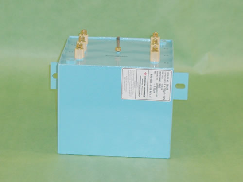
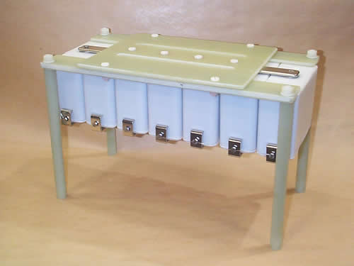
Six capacitors supplied in one package for a laser PFN application
General Atomics Energy Products (GAEP) produces both individual capacitors used in PFNs, such as the plastic case units shown as an assembly for a medical accelerator application, and multiple capacitors in a single case. The unit shown here contains six individual capacitors with one common terminal, and is used in a dermatology laser application. In addition, GAEP can design and manufacture complete PFN assemblies to meet your output pulse specifications. GAEP can also produce complete pulsed power or power electronic systems.
SPECIFYING A PULSE FORMING NETWORK
Output voltage and tolerance. Note that the output voltage is half the charge voltage on the capacitors in the Type-E network.
Characteristic impedance and tolerance. The standard value is 50 ± 5 ohms. If the load impedance is not to be matched to the network impedance, define both.
Pulse Risetime is normally specified between 10% and 90% of the average pulse amplitude.
Pulse Width is normally specified as the time between the 70% average pulse amplitude points (the half power points).
Ripple is defined as the peak-to-peak voltage above and below the average peak amplitude when the PFN is discharged into a non-reactive load. Nominal design ripple value is ± 5%, and lower ripple tolerances are possible when required. Specify the maximum allowable ripple tolerance.
Pulse Decay or Fall Time (if important)
Pulse Repetition Rate and Duty Cycle are important for thermal analysis. The duty cycle should be definitively expressed in terms of seconds on and seconds off, rather than just a percentage.
Ambient Temperature Range (Operating and Storage) in °C. GAEP's standard temperature range is -35 to +65 °C, but other ranges can be accommodated.
Operating Life should be expressed in either total charge/discharge cycles or in hours of operation. (Note: GAEP will normally quote Design Life at the 90% survival reliability level unless otherwise specified.)
Mechanical requirements, including number of terminals, mounting brackets, size and weight constraints, vibration and shock requirements, etc.
Environmental conditions, including forced air circulation or natural convection, oil or pressurized gas insulation, altitude, interior or exterior installation, etc