
4 - Amp Inhibiting Circuit Vs Voltage Enhancement
Amp Inhibiting Circuit Vs Voltage Enhancement
 Beyond amp restricting characteristic of said Amp Inhibiting Circuit of Figure (1-18) as to
VCI VIC Dual Single-coil Assembly (Figure 1-19A) and VIC Bifilar-Wrap Coil Assembly (Figure -1
1-19B), the spiral-wrapped coils being paired together, also, causes voltage level enhancement
beyond applied voltage input since the "Distributed Capacitance"Capacitance" (Cl xxx Cln =C2a xxx C2n) /
"Distributed Inductance" (FLaFL1a xxx FLnFL1n = FL2a xxx FL2n) of said "Bifilar" wrapped coils
encourages the compounding effect (increasing magnetic field-strength during each pulsing cycle)
cycle) of electromagnetic field-strength (Rpla xxx Rpin = Rp2a xxx Rp2n) (mutual induction)induction) when
applied Pulse-Voltage Frequency (49a xxx 49n) passes through the positive energized Resonant
Charging Choke (56).
|
Figure 1-19A
|
Figure 1-19B |
 Furthermore, the paired coils-wires opposite voltage potential [positive
electrical attraction force (B+) equaling negative electrical force (B-)] [herein called "ElectricalStress" Stress" (SS' = RR") as to (160) of Figure (3-26)] are always equal in electrical magnitude/electrical
intensity since the wire-length of each coil are the same.
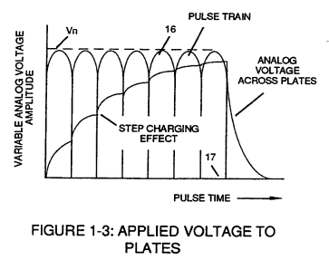
Pulse-Voltage repetition rate sets up the
step-up electrical charging effect (Figure 1-3) since the "Resonant Cavity" functions as a CapacitorER) ER) due to the dielectric value (Resistance to amp flow)flow) of water which becomes an integral partfothe for the VIC Circuit, as so illustrated in (650) of Figure (7-4).
|
Figure 1-3
|
(650) of Figure (7-4)
|
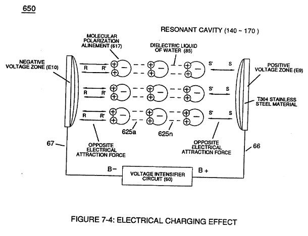
The resultant voltage enhancement
(Voltage Amplitude)Amplitude) can exceed 40 kilovolts to instantly convert water (droplets) into thermal
explosive energy (gtnt), as so illustrated in voltage Intensifier Circuit Diagram (Figure 1-18).
Both
VIC Dual Single-Coil (Figure 1-19A) and VIC Bifilar-Wrap Coil (Figure 1-19B) function similarly
without incurring amp influxing. (See WFC U.S. Patent Validation Report titled "Natural Water
Hydrogen Generation System filed September 16,1981)1981)
|
Figure 1-19A
|
Figure 1-19B |