A Hydrogen Gas Fuel And Management System For An Internal Combustion Engine Utilizing Hydrogen Gas Fuel #5,293,857
PDF Download: Meyer #5,293,857 A Hydrogen Gas Fuel And Management System For An Internal Combustion Engine Utilizing Hydrogen Gas Fuel.pdf
ABSTRACT:
A gas fuel for an internal combustion engine comprising a mixture of gases having a proportion of hydrogen to oxygen of approximately 2:1 and a regulated density of the hydrogen component of the mixture such that the burn rate of the mixture approximates that of a fossil fuel and a system for maintaining the foregoing gas fuel mixture and characteristics in an internal combustion engine.
DESCRIPTION OF DRAWINGS:
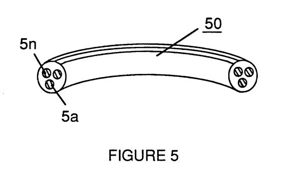
FIG. 1 shows the combustion envelope of hydrogen compared to the combustion envelope of gasoline and illustrates a goal achieved by the invention in maintaining an optimum and uniform combustion rate for hydrogen throughout the effective range of engine RPM. As used herein, the "combustion envelope" refers to the range within which combustion of a fuel gas is possible, given a predetermined quantity of combustible fuel and its ratio to the combustion media, i.e. oxygen.)
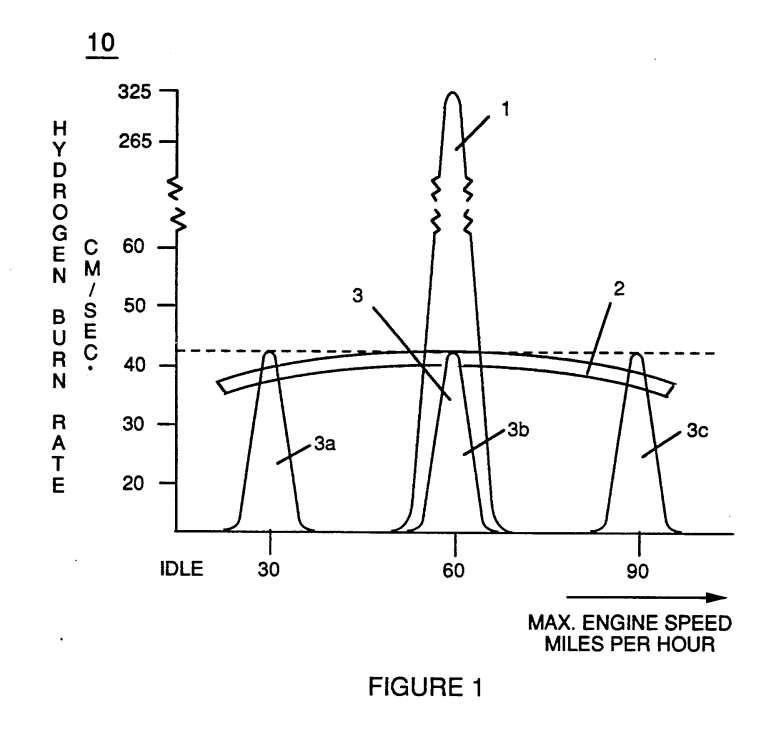
FIG. 2 is a block diagram of a combustion management system for a hydrogen containing fuel gas mixture that is injected into a combustion chamber, showing the interrelationship of system management controls with various engine parameters.
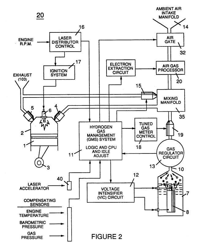
FIG. 3 illustrates the physical arrangement of a hydrogen fuel gas control means and injection system for the regulation of fuel gas transmitted to an engine combustion chamber.
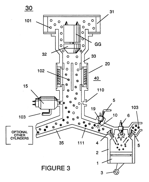
FIG. 4 shows an air gas processor useful in the system of the invention in a cross-sectional side view; FIG. 4A shows a top plan view; and FIG. 4B is a bottom view.
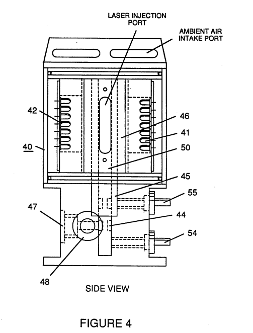
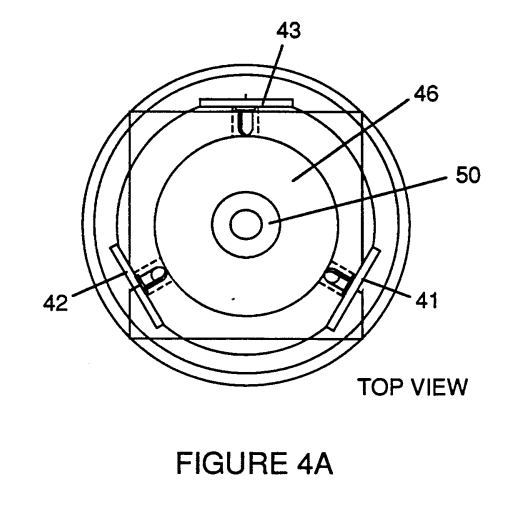
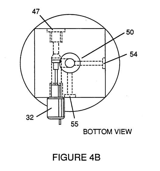
FIG. 5 shows a "quenching conduit" for the safe distribution of a hydrogen fuel in the engine environment, and FIGS. 5A and 5B shows alternative cross section configurations for said conduit.