A Hydrogen Gas Fuel And Management System For An Internal Combustion Engine Utilizing Hydrogen Gas Fuel #5,293,857
PDF Download: Meyer #5,293,857 A Hydrogen Gas Fuel And Management System For An Internal Combustion Engine Utilizing Hydrogen Gas Fuel.pdf
ABSTRACT:
A gas fuel for an internal combustion engine comprising a mixture of gases having a proportion of hydrogen to oxygen of approximately 2:1 and a regulated density of the hydrogen component of the mixture such that the burn rate of the mixture approximates that of a fossil fuel and a system for maintaining the foregoing gas fuel mixture and characteristics in an internal combustion engine.
Hydrogen has long been regarded as an efficient, abundant and potentially non-polluting energy source. Yet despite such desirable attributes, hydrogen has not been widely, or practically, applied in applications where the use of hydrogen as a fuel is self-evidently desirable, such as in motor vehicles powered by internal combustion engines. In part, practical use of hydrogen is inhibited by difficulties in the safe transmission of the gas. Hydrogen has an inherent high volatility and a correspondingly rapid dispersion characteristic in other gas mixtures such as the atmosphere. Further, it is difficult to control the distribution of a hydrogen gas fuel and to maintain consistent combustion characteristics for a hydrogen gas fuel, particularly in a motor vehicle internal combustion engine.
OBJECTS:
- It is an object of this invention to overcome such difficulties and to provide a fuel gas management and delivery system for internal combustion engines that utilize hydrogen as a fuel. The system includes a safe and effective distribution means for supplying a hydro- gen fuel to an internal combustion engine, means for fuel injection applications of hydrogen fuel in such an engine, means for controlling the burn rate of hydrogen for the efficient use of a hydrogen fuel gas, and means for overcoming prior art problems of engine shut down caused by an over-enrichment of hydrogen in the fuel supply to the engine.
- In particular, when hydrogen gas fuel is used in a motor vehicle internal combustion engine, an over-enrichment of the hydrogen component of the fuel gas injected into the engine frequently occurs and results either in (1) an engine shut down, because of the narrow combustion window (a term defined hereinafter) for hydrogen, or (2) a significant waste of the "over-enriched" portion of the fuel not combusted—the fuel is expelled in the engine exhaust. In prior art attempts, mechanical meters, valves and switches that were conventionally used in engine fuel systems for petroleum based, fossil fuels were too slow to adapt to engine conditions. Similarly, prior art system included processors that were intended to control the engine in view of predetermined operating parameters with little regard for engine effects caused by the injection of a hydrogen fuel. As a result over-enrichment of hydrogen in the fuel/combustion mixture consistently remains a problem in the development of a hydrogen fueled internal combustion engine. Conventional hydrogen fueled engines are prone to shut down and do not smoothly operate over the extended range of engine speeds considered desirable and necessary in a motor vehicle.
- It is accordingly an object of this invention to provide a fuel distribution system for a hydrogen fueled internal combustion engine that reduces the problem of fuel over-enrichment and provides a smooth operating characteristic for engine speeds required in conventional use.
- It is also an object to provide a "tuned" combustion system, adaptable not only for hydrogen, but also to other fuel stocks by which optimum combustion characteristics are maintained for the fuel over the operating range of the engine.
- And it is a further object to provide an integrated operating system including fuel generation and control means for a hydrogen fueled internal combustion engine.
- These and other objects of the invention will become evident to those of skill in the art when the following description of the preferred embodiment is considered in conjunction with the drawings in which:
DESCRIPTION OF DRAWINGS:
FIG. 1 shows the combustion envelope of hydrogen compared to the combustion envelope of gasoline and illustrates a goal achieved by the invention in maintaining an optimum and uniform combustion rate for hydrogen throughout the effective range of engine RPM. As used herein, the "combustion envelope" refers to the range within which combustion of a fuel gas is possible, given a predetermined quantity of combustible fuel and its ratio to the combustion media, i.e. oxygen.)
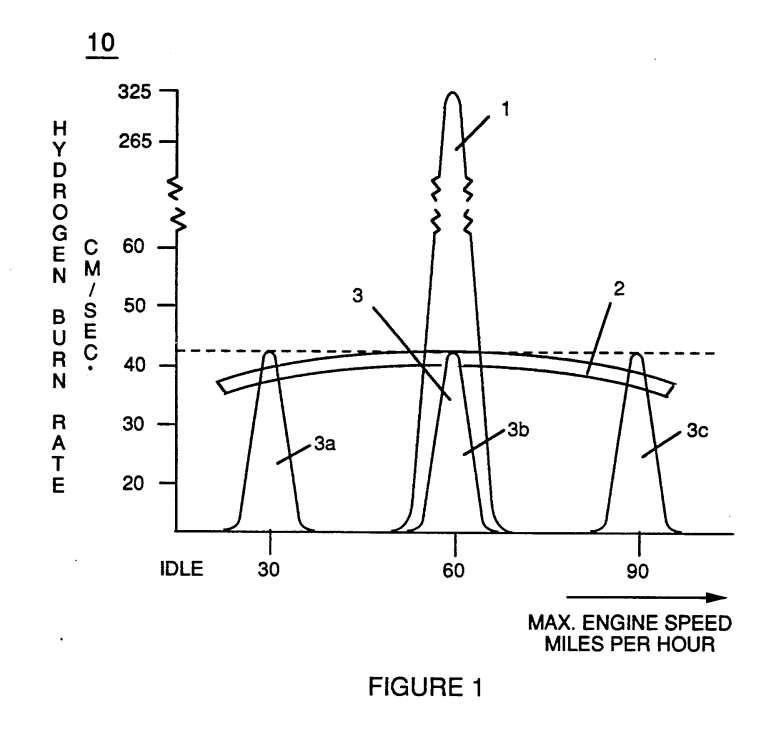
FIG. 2 is a block diagram of a combustion management system for a hydrogen containing fuel gas mixture that is injected into a combustion chamber, showing the interrelationship of system management controls with various engine parameters.
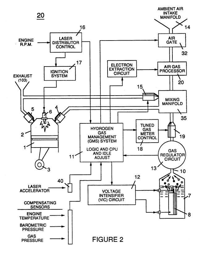
FIG. 3 illustrates the physical arrangement of a hydrogen fuel gas control means and injection system for the regulation of fuel gas transmitted to an engine combustion chamber.
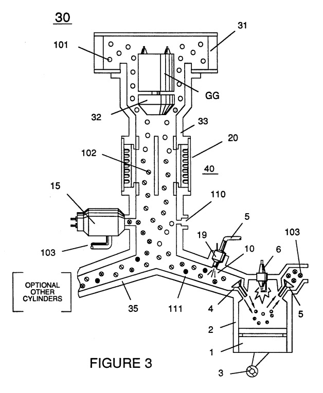
FIG. 4 shows an air gas processor useful in the system of the invention in a cross-sectional side view; FIG. 4A shows a top plan view; and FIG. 4B is a bottom view.
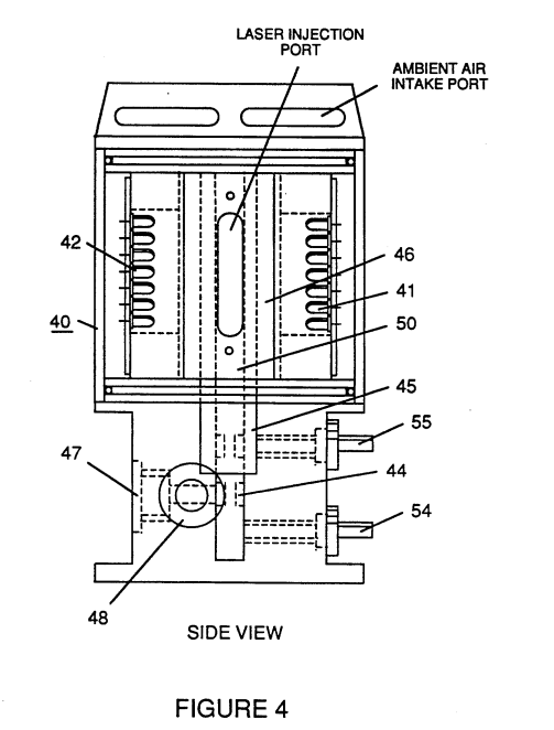
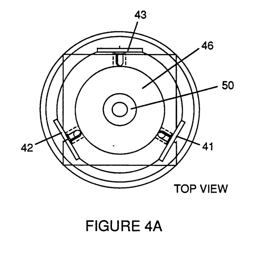
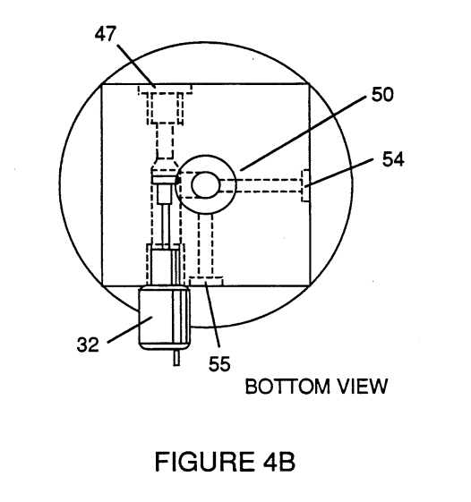
FIG. 5 shows a "quenching conduit" for the safe distribution of a hydrogen fuel in the engine environment, and FIGS. 5A and 5B shows alternative cross section configurations for said conduit.
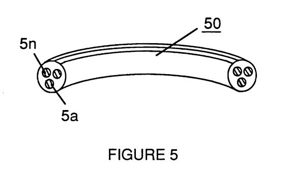
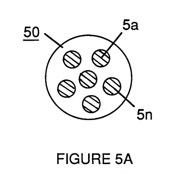
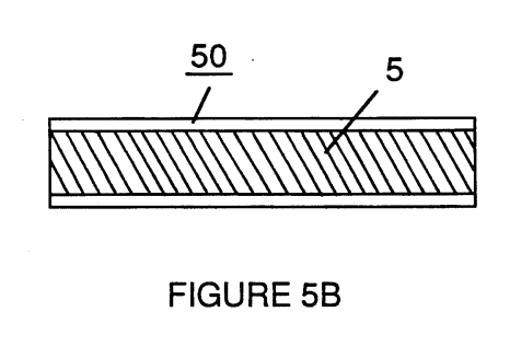
FIG. 6 figuratively represents the modulating effect upon hydrogen gas characteristics of other non-combustible gases included in a fuel gas mixture containing hydrogen in accord with the invention and its fuel gas management system.
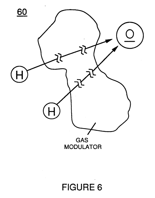
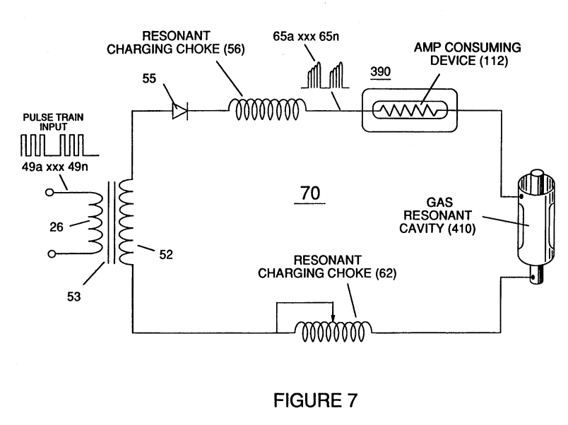
FIG. 7 shows the electron extractor circuit used in the air processor section to ionize and maintain the ionization of introduced air gas.