Electrical Pulse Generator #4,613,779
PDF Download: Meyer #4,613,779 Electrical Pulse Generator.pdf
ABSTRACT:
An electrical pulse generator comprising a series of electromagnets spatially positioned about the outer circumference of a disc-like base and a second series of complimentary electromagnets positioned about an inner position on said disc. One of each of said first and second series electromagnets positioned relative to each other creating a magnetic field therebetween. A second disc-like base rotatable above and parallel with said first disc. A continuous coil winding ring mounted on the underside of said second disc and positioned relative to said first and second series of electromagnets to traverse said magnetic field upon rotation of said second disc and thereby inducing a voltage/current potential in said coil winding.
BACKGROUND:
Power supplies for electrical systems have been utilized for a century or so. As time progressed new uses of electrical systems placed a need for more sophisticated systems. One particular utilization is the need for power transfer to the utilization device but yet with the requirement that there be power isolation. The advancement of electronics and power devices such as SCRs, Triacs and the such, appeared to be an obvious solution to such a power transfer. Current limiting circuits also were developed. Unfortunately, the solution was not met. The electronic devices in most instances could not limit or tolerate high power. Finally, it became apparent that the electrical systems, with this type of current limiting requirement necessitated electrical power supplies—not electronic. A very ineffective device is the auto alternator that will provide an increased power output with limited current. However this device, too, with it's sufferings, such as opposing magnetic fields, rubbing contacts and the such, made this device very inefficient.
SUMMARY OF INVENTION:
The electrical generator of the present invention is a substantial improvement of the state of the art in power isolation and power transfer and particularly the conventional alternator. A practical working embodiment has no contacts and no opposing magnetic fields. Also of equal significance is that the voltage output is variably dependent on several controllable features. The structure comprises a series of electromagnets positioned on the outer periphery of a stationary disc. A second series of electromagnets are positioned about the inner circumference of the stationary disc. One of each of said first and second series of electromagnets are positioned relative to one another to create a magnetic field therebetween when energized. A second disc has positioned on its underside a winding coil having a non-magnetic ring with a continuous winding thereon, extending downwardly between said first and second series of electromagnets.
The winding is positioned between the first and second series of electromagnets in the magnetic field created thereby. Upon rotation of the second disc the continuous winding on the ring traverses the magnetic fields and in turn the magnetic fields induce a voltage in the windings on the ring. In a preferred embodiment, a third and fourth series of electromagnets are positioned on the upper side of the rotatable disc much in the same manner as the first and second series of electromagnets positioned on said first stationary disc. The voltage/current induced in said first ring winding is utilized to energize said third and fourth electromagnets to create a second magnetic field therebetween. The second non-magnetic ring traverses the second magnetic field, causing an electrical potential for utilization. The apparatus does not have contact rings or brushes, nor are there opposing magnetic forces. Simi- lar arrangements are cascaded for voltage multiplication. Multiple windings on each ring provide independent outputs for multiple utilization devices.
OBJECTS:
It is a principal object of the present invention to provide an electrical arrangement that is power isolated but yet, permits increased power transfer to a utilization device. Another object of the present invention is to provide such an electrical system that is free of opposing magnetic fields, contacts, slip rings, moving wires, and the like. Another object of the present invention is to provide such an electrical system that has an output potential that may be varied in magnitude. Another object of the present invention is to provide a structure that is not affected in size and that may be duplicated in cascade for high power outputs. Still another object of the present invention is to provide a winding ring having induced therein multiple discrete voltages. Other objects and features will become apparent from a detailed description of the invention when taken in conjunction with the drawings in which:
BRIEF DESCRIPTION OF DRAWINGS:
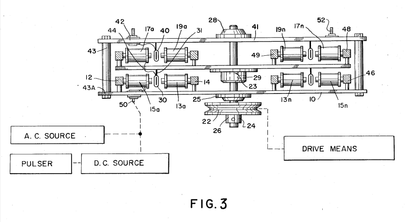
FIG. 1 is a top view illustrating a first and second series of electromagnets positioned on a first and second metallic base plate in a physical relationship to create a magnetic field therebetween.
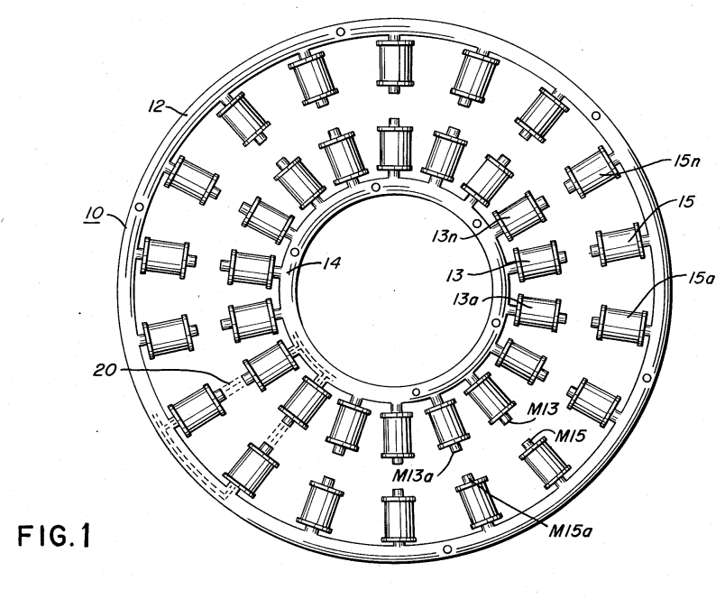
FIG. 2 is a schematic illustration of a non-magnetic 30 ring having a secondary winding wound thereon and FIG. 2A illustrates multiple windings with discrete voltage terminals wound on the ring.
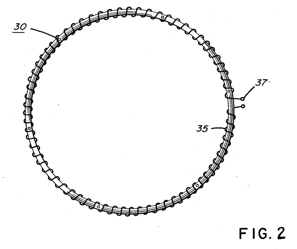
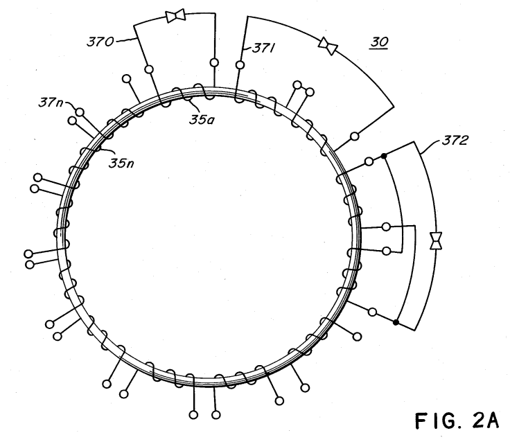
FIG. 3 is a cross-sectional view of a complete preferred embodiment.