Hydrogen Gas Injector System For Internal Combustion Engine #4,389,981
PDF Download: Meyer #4,389,981 Hydrogen Gas Injector System For Internal Combustion Engine.pdf
ABSTRACT:
System and apparatus for the controlled intermixing of a volatile hydrogen gas with oxygen and other non-combustible gasses in a combustion system. In a preferred arrangement the source of volatile gas is a hydrogen source, and the non-combustible gasses are the exhaust gasses of the combustion system in a closed loop arrangement. Specific structure for the controlled mixing of the gasses, the fuel flow control, and safety are disclosed.
CROSS REFERENCES AND BACKGROUND:
There is disclosed in my co-pending U.S. patent application Ser. No. 802,807 filed Sept. 16, 1981 for a Hydrogen-Generator, a generating system converting water into hydrogen and oxygen gasses. In that system and method the hydrogen atoms are disassociated from a water molecule by the application of a non-regulated, non-filtered, low-power, direct current voltage electrical potential applied to two non-oxidizing similar metal plates having water passing there-between. The sub-atomic action is enhanced by pulsing the non-regulated and non-filtered direct current voltage. The apparatus comprises structural configurations in alternative embodiments for segregating the generated hydrogen gas from the oxygen gas.
In my co-pending patent application filed May 1981, U.S. Ser. No. 262,744 now abandoned for Hydrogen-Aeration Processor, non-volatile and non-combustible gasses are controlled in a mixing stage with a volatile gas. The hydrogen aeration processor system utilizes a rotational mechanical gas displacement system 25 to transfer, meter, mix, and pressurize the various gasses. In the gas transformation process, ambient air is passed through an open flame gas-burner system to eliminate gasses and other present substances. Thereafter the non-combustible gas-mixture is cooled, filtered 30 for impurity removal, and mechanically mixed with a
pre-determined amount of hydrogen gas. There results a new synthetic gas. The synthetic gas formation stage also volume meters and determines the proper gas-mixing ratio for establishing the desired burn-rate of hydrogen gas. The rotational mechanical gas displacement system in that process determines the volume-amount of synthetic gas to be produced.
The above noted hydrogen aeration processor, of my co-pending patent application, is a multi stage system having utility in special applications. Whereas the hydrogen generator system of my other mentioned co-pending application does disclose a very simple and unique hydrogen generator.
In my co-pending patent application Ser. No. 315,945, filed Oct. 18, 1981 there is disclosed a combustion system having utility on a mechanical drive system. Particularly in one instance to drive a piston in an automotive device. There is shown a hydrogen generator for developing hydrogen gas, and perhaps other non-volatile gasses such as oxygen and nitrogen. The hydrogen gas with the attendant non-volatile gasses are fed via a line to a controlled air intake system. The combined hydrogen, non-volatile gasses, and the air after inter-mixing are fed to a combustion chamber where it is ignited. The exhaust gasses of the combustion chamber are returned in a closed loop arrangement to the mixing chamber for the mixture of volatile and non-combustible gasses. Particular applications and structural embodiments of the system are disclosed.
SUMMARY OF INVENTION:
The system of the present invention in its most preferred embodiment is for a combustion system utilizing hydrogen gas; particularly to drive a piston in an automobile device. The system utilizes a hydrogen generator for developing hydrogen gas. The hydrogen gas and other non-volatile gasses are fed to a mixing chamber also having oxygen fed thereto. The mixture is con-
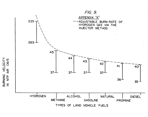
trolled to regulate the burning temperature; that is, to lower the temperature velocity of the hydrogen gas to that of the commercial fuels. The hydrogen gas feed line to the combustion chamber includes a fine linear control gas flow valve. An air intake is the source of oxygen and it also includes a variable valve. The exhaust gasses from the combustion chamber are utilized in a controlled manner as the non-combustible gasses.
The hydrogen generator is improved upon to include a holding tank to provide a source of start-up fuel. Also, the hydrogen gas generator includes a switch to the power source operable from one position to another dependent upon a pressure sensing switch on the combustion chamber. The simplified structure includes a series of one-way valves, safety valves, and quenching apparatus. The combination of apparatus comprises the complete assembly for converting the standard automobile engine from gasoline (or other fuels) to the hydrogen gas mixture.
OBJECTS:
- It is accordingly a principal object of the present invention to provide a combustion system of gasses combined from a source of hydrogen and non-combustible gasses.
- Another object of the invention is to provide such a combustion system that intermixes the hydrogen and non-combustible gasses in a controlled manner and an thereby control the combustion temperature.
-
A further object of the invention is to provide such a combustion system that controls the fuel flow to the combustion chamber in s system and apparatus particularly adapted to hydrogen gas. Still other objects and features of the present invention will become apparent from the following detailed description when taken in conjunction with the drawings in which:
BRIEF DESCRIPTION OF DRAWINGS:
FIG. 1 is a mechanical schematic illustration partly in block form of the present invention in its most preferred embodiment.
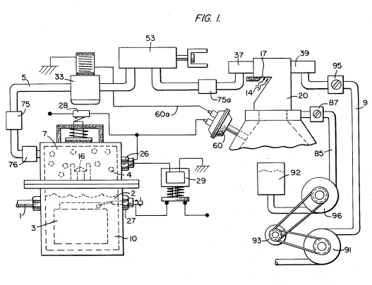
FIG. 2 is a block schematic illustration of the preferred embodiment of the hydrogen injector system of FIG. 1.
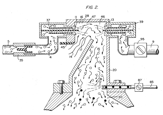
FIG. 3 is the fine linear fuel flow control shown in FIG. 1.
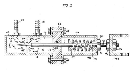
FIG. 4 is cross-sectional illustration of the complete fuel injector system in an automobile utilizing the concepts of the present invention.
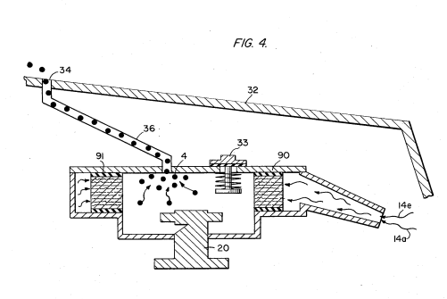
FIG. 5 is a schematic drawing in a top view of the fuel injector system utilized in the preferred embodiment.
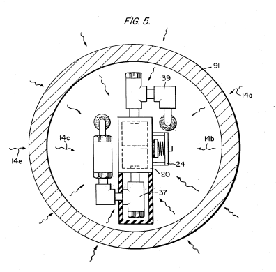
FIG. 6 is a cross-sectional side view of the fuel injector system in the present invention.
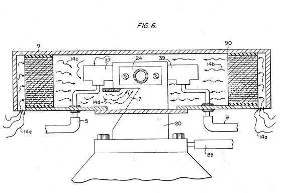
FIG. 7 is a side view of the fuel mixing chamber. 60
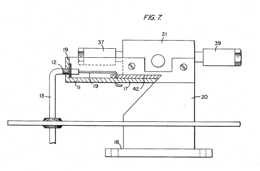
FIG. 8 is a top view of the air intake valve to fuel mixing chamber.
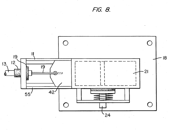
FIG. 9 is a comparison of the burning velocity of hydrogen with respect to other fuels.