Process & Apparatus For The Production Of Fuel Gas & The Enhanced Release Of Thermal Energy From Such Gas #5,149,407
PDF Download: Meyer #5,149,407 Process & Apparatus For The Production Of Fuel Gas & The Enhanced Release Of Thermal Energy From Such Gas.pdf
ABSTRACT:
Water molecules are broken down into hydrogen and oxygen gas atoms in a capacitive cell by a polarization and resonance process dependent upon the dielectric properties of water and water molecules. The gas atoms are thereafter ionized or otherwise energized and thermally combusted to release a degree of energy greater than that of combustion of the gas in ambient air.
FIELD OF THE INVENTION:
This invention relates to a method of and apparatus for obtaining the release of a fuel gas mixture including hydrogen and oxygen from water and to a method of and apparatus for obtaining the further release of energy from such a fuel gas mixture. Charged ions derived from the fuel gas are stimulated to an activated state, and then passed through a resonant cavity, where successively increasing energy levels are achieved, and finally passed to an outlet orifice to produce thermal explosive energy.
PRIOR ART:
Numerous processes have been proposed for separating a water molecule into its elemental hydrogen and oxygen components. Electrolysis is one such process. Other processes are described in U.S. patents such as U.S. Pat. Nos. 4,344,831; 4,184,931; 4,023,545; 3,980,053; and Patent Cooperation Treaty Application No. PCT/US80/1362, published Apr. 30, 1981. Other processes have been proposed for many years in which controlled energy producing reactions of atomic particles are expected to occur under “cold” conditions. [See, e.g., Rafelski, J. and Jones, 8. E., “Cold Nuclear Fusion,” Scientific American, July, 1987, page 84].
Further processes are also described in U.S. Pat. Nos. 4,233,109; 4,406,765; 4,687,753 and 4,695,357. The process and apparatus described herein are considered variations to and improvements in fuel sources and processes by which energy is derived from fuel gas components in a controllable manner.
OBJECTS OF THE INVENTION:
- A first object of the invention is to provide a fuel cell and a process in which molecules of water are broken down into hydrogen and oxygen gases, and a fuel gas mixture including hydrogen, oxygen and other gasses formerly dissolved within the water is produced. A further object of the invention is to realize significant energy-yield from a fuel gas derived from water (H20) molecules. Molecules of water are broken down into hydrogen and oxygen gases. Electrically charged hydrogen and oxygen ions of opposite electrical polarity are activated by electromagnetic wave energy and ex- posed to a high temperature thermal zone. Significant amounts of thermal energy with explosive force beyond the gas burning stage are released.
- An explosive thermal energy under a controlled state is produced. The process and apparatus provide a heat energy source useful for power generation, aircraft, rocket engines, or space stations.
DRAWINGS:
FIG. 1: 1A through 1F are illustrations depicting the theoretical bases for phenomena encountered during operation of the fuel gas production stage of the invention herein.
FIG. 2 Illustrates a circuit useful in the fuel gas generation process.
FIG. 3 shows a perspective of a “water capacitor” element used in the fuel cell circuit.
FIG. 4 illustrates a staged arrangement of apparatus useful in the process, beginning with a water inlet and culminating in the production of thermal explosive energy.
FIG. 5A shows a cross-section of a circular gas resonant cavity used in the final stage assembly of FIG. 4
FIG. 5B shows an alternative final stage injection system useful in the apparatus of FIG. 4.

FIG. 5C shows an optical thermal lens assembly for use with either final stage of FIG. 5A or FIG. 5B
FIGS. 6A, 6B, 6C and 6D are illustrations depicting various theoretical bases for atomic phenomena expected to occur during operation of the invention herein.
FIG. 7 is an electrical schematic of the voltage source for the gas resonant cavity.
FIGS. 8A and 8B, respectively, show (A) an electron extractor grid used in the injector assemblies of FIG. 5A and FIG. 5B, and (B) the electronic control circuit for the extractor grid.
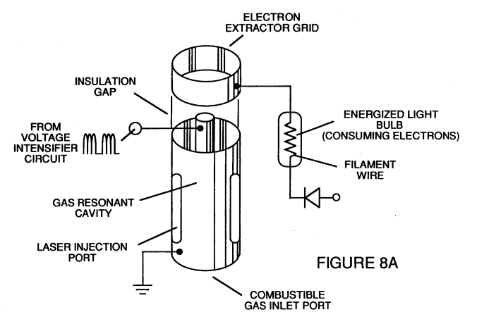
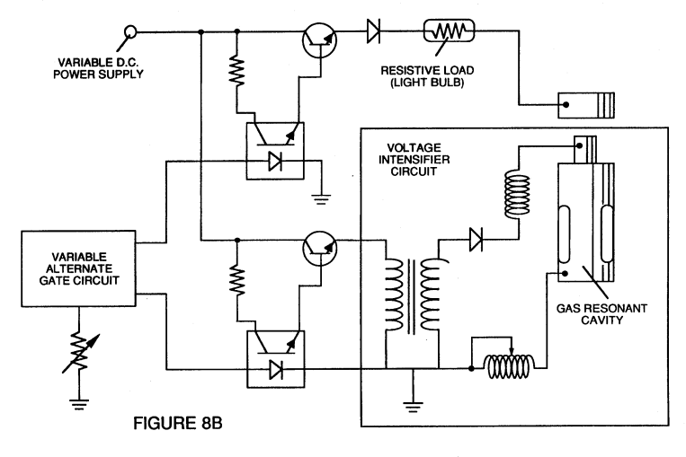
FIG. 9 shows an alternate electrical circuit useful in providing a pulsating waveform to the apparatus.