
StartUp ShutDown For A Hydrogen Gas Burner #4,465,455
PDF Download: Meyer #4,465,455 StartUp ShutDown For A Hydrogen Gas Burner.pdf
ABSTRACT:
System for flame start-up/shut-down for a hydrogen gas mixture burner. An electrical probe igniter positioned adjacent the gas port outlet. On demand the igniter is actuated to heat and electrically heat a thermal switch. Responsive electronic controls actuate the appropriate valves and circuits for operational start-up. Upon the ignition of the generated hydrogen gas mixture, a second thermal probe is heated by the flame to deactivate the ignition and start-up circuits. After demand the second thermal probe cools and the circuit is restored for start-up again. A safety probe positioned in the flame is quiescent. In the event of demand time shut-down, the safety probe will activate the circuits for restart. If failure to start-up continues for a predetermined time, the safety probe circuit will effect permanent shut-down.
CROSS REFERENCES:
In the non-electrolysis process disclosed and claimed in my co-pending patent application, Ser. No. 302,807, Filed: Sept. 16, 1981, For: HYDROGEN GENERATOR SYSTEM, for separating hydrogen and oxygen atoms from water, water is passed between two plates of similar non-oxidizing metal. The one plate has placed thereon a positive potential and the other a negative potential from a very low-direct-current power source. The sub-atomic action of the direct current voltage causes the hydrogen and oxygen atoms to be separated. The contaminants in the water are forced also to disassociate itself and may be collected or utilized and disposed of. This in turn lends the process to recombining the hydrogen and oxygen into pure water.
The direct current voltage applied to the plates is non-regulated and non-filtered. The direct current acts as a static force on the water molecules; whereas the rippling direct current voltage acts as a dynamic force. Pulsating the direct current further acts as a dynamic force and enhances considerably the splitting of the 25 atoms from the water molecules. An increase in voltage potential further increases the hydrogen output. Certain plate arrangements and configurations with graphical illustration or relative efficiency are disclosed.
In my co-pending patent application, Ser. No. 30 422,495, Filed: Sept. 24, 1982, For: PERIODIC FLUSH SYSTEM FOR NON-ELECTROLYSIS HYDROGEN GENERATOR, there is disclosed control apparatus and electrical circuitry for periodically shutting down the hydrogen generator for flushing out the 35 accumulated contaminates. The shut-down is in a sequential step-by-step operation. After the flushing is complete, the hydrogen generator is started up and, again, in a sequential step-by-step operation. Although the functions are numerous, the most critical is the 40 opening and closing of the gas valves, and the switching on and off of the electrical circuitry to the exciter elements.
BACKGROUND:
Heating and air environmental systems of the prior art have included sensing systems for flame-out, power loss or the like. These systems do provide some form of shut-down upon occurrence of a malfunction. However, the prior art systems are either of gas, oil, or electrical. Although a gas or oil furnace will utilize electrical circuitry for a blower, the energy, whether gas, oil, or electric, is supplied either by a utility or in bulk. None of the prior art systems generate the energy that is used in the heating or air control system. Accordingly, no monitoring systems for the generator systems are known in the prior art, that are applicable heating or
air control systems.
SUMMARY OF INVENTION:
The present invention in its preferred embodiment provides a monitoring system and a start-up/shut-down circuitry and apparatus for a hydrogen gas burner. The system is distinctive in that the hydrogen generator is a demand system; that is, hydrogen gas is generated only when the thermostat (or other gauge) dictates the energy is needed. Accordingly, the start-up is the start-up of the energy generating system and thereafter starting the igniter to ignite the hydrogen gas mixture. Further, although the prior systems start-up on demand; none have a need for periodic shut-down.
The present invention is a start-up/shut-down system for an energy generator and for the utilization of the
energy generated. The function in addition to demand is periodic. Then, again, the same procedure is followed upon the occurrence of malfunction. The apparatus comprises an igniter in the flame path that upon actuation heats a thermal probe that controls the electrical/electronic circuitry for opening and closing the various controls and switches. Another probe deactivates the ignition and start-up upon completing the function. A safety probe positioned in the flame path is time controlled to start-up in the occurrence of a flame-out, if failure occurs in the attempt to retract within a given period of time the entire system is shut-
down.
OBJECTS:
- It is a principal object of the present invention to provide a monitoring and control system for start-up and shut-down of an energy generator system.
- Another object of the present invention is to provide such a control system that is operable upon demand, periodically operable, and operable upon occurrence of a malfunction.
- A further object of the invention is for a monitoring and control system that distinguishes between an accidental flame-out and a flame-out caused by malfunction of the system.
- A further object of the invention is for a monitoring and control system that provides a restart function upon accidental flame-out. Other objects and features of the present invention will become apparent from the following detailed description when taken in conjunction with the drawings in which:
BRIEF DESCRIPTION OF DRAWINGS:
FIG. 1 schematically depicts a preferred embodiment of the invention of a hydrogen gas mixture burner incorporating the features of the invention.
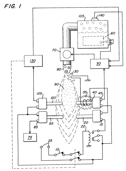
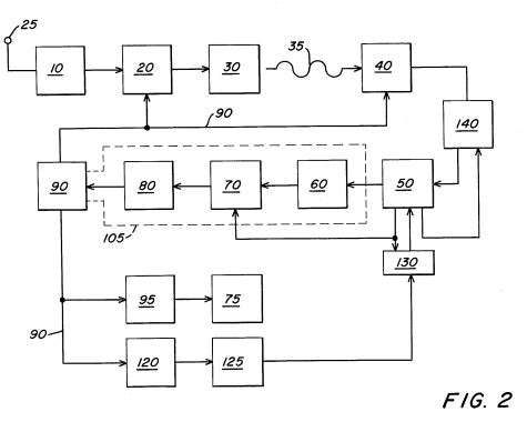
FIG. 2 is a schematic block diagram of the preferred embodiment in a complete operational generator system.
DETAILED DESCRIPTION OF DRAWINGS:
With reference to FIG. 1 there is a illustrated schematically the mechanical/electrical apparatus of the system of the preferred embodiment of the invention taken in conjunction with the hydrogen generator of my co-pending patent application, supra. In FIG. 2 the electrical circuitry and actuating valves and the like are depicted in a sequential schematic block type of arrangement. Referring to FIG. 1, together with FIG. 2, the preferred embodiment of the present invention may now be described. the thermal probe switch 20, before start-up, is in a normally closed position. Upon the demand for energy, dictated by the thermostat 10 control, the relay 22 is closed, applying electrical power from source 25 to the electrical spark igniter 30 through the closed thermal probe 20. Upon the spark igniter 30 attaining the appropriate temperature, the radiant heat from coil 35 heats the thermal probe 40.