

Figures by number: the dealership manual and its extension
26 September 2026
An index of the figures in Stan Meyer's dealership manual, by number, with the drawing the archive holds beside each. The index itself was posted on 5 April 2014 as a work in progress, "with thanks to GNPTrust for permission to create and post an index to their upcoming ETM book". Its page references (ETM) are to that book, a later and expanded version of the 1986 Dealership Sales Manual; most of them also work for the 1986 edition.
The archive holds 68 of the 120 figures the index lists, on the pages of the Dealership Sales Manual and the extended manual. Each was matched by the number and title printed on the drawing, not by the index's wording, and the two disagree in a few places, noted beside the figure. Click a drawing for the full image. Titles are the index's, with its spelling corrected.
The circuit boards, component layouts and wiring harnesses of the 9X and 20Y series are the gap: the index lists them from the ETM book, and the archive has only a few of them.
Water and voltage
| Figure | Drawing | In the archive |
|---|---|---|
| 1 Energy Gap · ETM C4 | 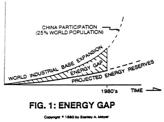 |
Pre-History To Development |
| 2 Electrical Polarization of Water | 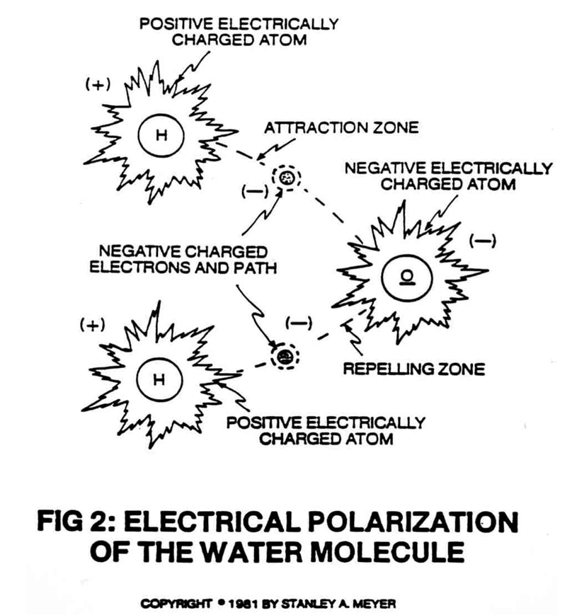 |
A Preview of Water Fuel Cell Technology and This Book; also The Principles of Discovery, Mega Watt Gas Yield |
| 3 Utilizing Voltage Potential to Split the Water Molecule | 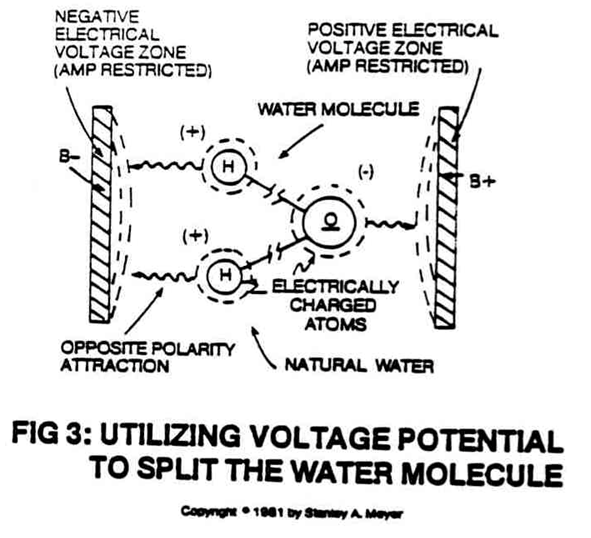 |
A Preview of Water Fuel Cell Technology and This Book; also The Principles of Discovery |
| 4 Electrical Polarization of the Water Molecules Occurs in All Natural Waters | 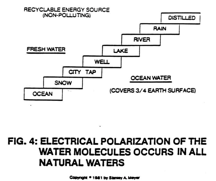 |
The Principles of Discovery |
| 5 Voltage Potential Performs Work without Amp Flow · ETM E3 | 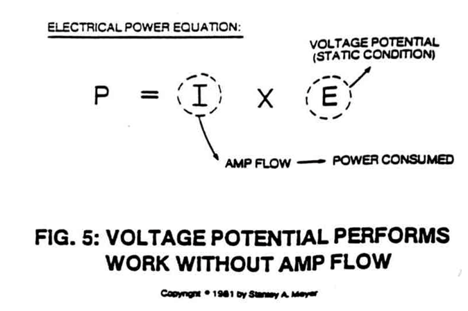 |
Operational Parameters of the Invention; also Voltage Attenuation Circuit |
| 7 Dissociation of the Water Molecule Is Directly Related to Applied Voltage · ETM E6 | 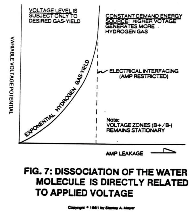 |
Operational Parameters of the Invention; also Voltage Attenuation Circuit |
| 8 Geometrical Shape of the Voltage Zones Alters Hydrogen Gas-Yield · ETM E7 | 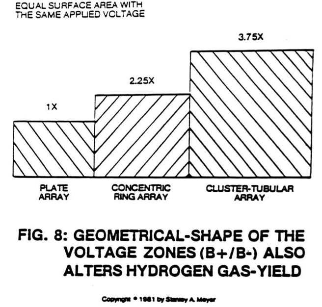 |
Operational Parameters of the Invention |
| 9 Voltage Intensifier Circuit · ETM E8 | 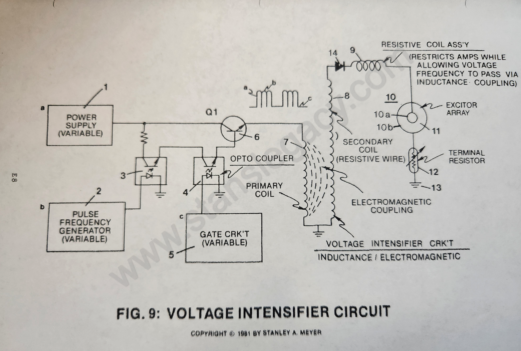 |
Voltage Attenuation Circuit |
| 9A Variable Pulse-Voltage Frequency Restricts Amps While Controlling Gas-Yield · ETM E9 | 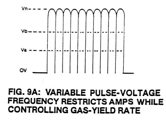 |
Spin Off Technology; also Operational Parameters of the Invention |
| 9B Variable Amplitude Unipolar Pulse-Voltage Frequency Superimposed onto 50% Duty Cycle Pulse Train Dynamically Controls the Hydrogen Gas Rate While Restricting Amp Flow · ETM E10 |  |
Operational Parameters of the Invention; also Spin Off Technology |
| 9BB Applied Voltage to Plates · ETM E11 | 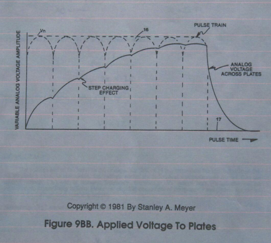 |
Voltage Attenuation Circuit |
| 9C Variable Gas-Rate Control Circuit | 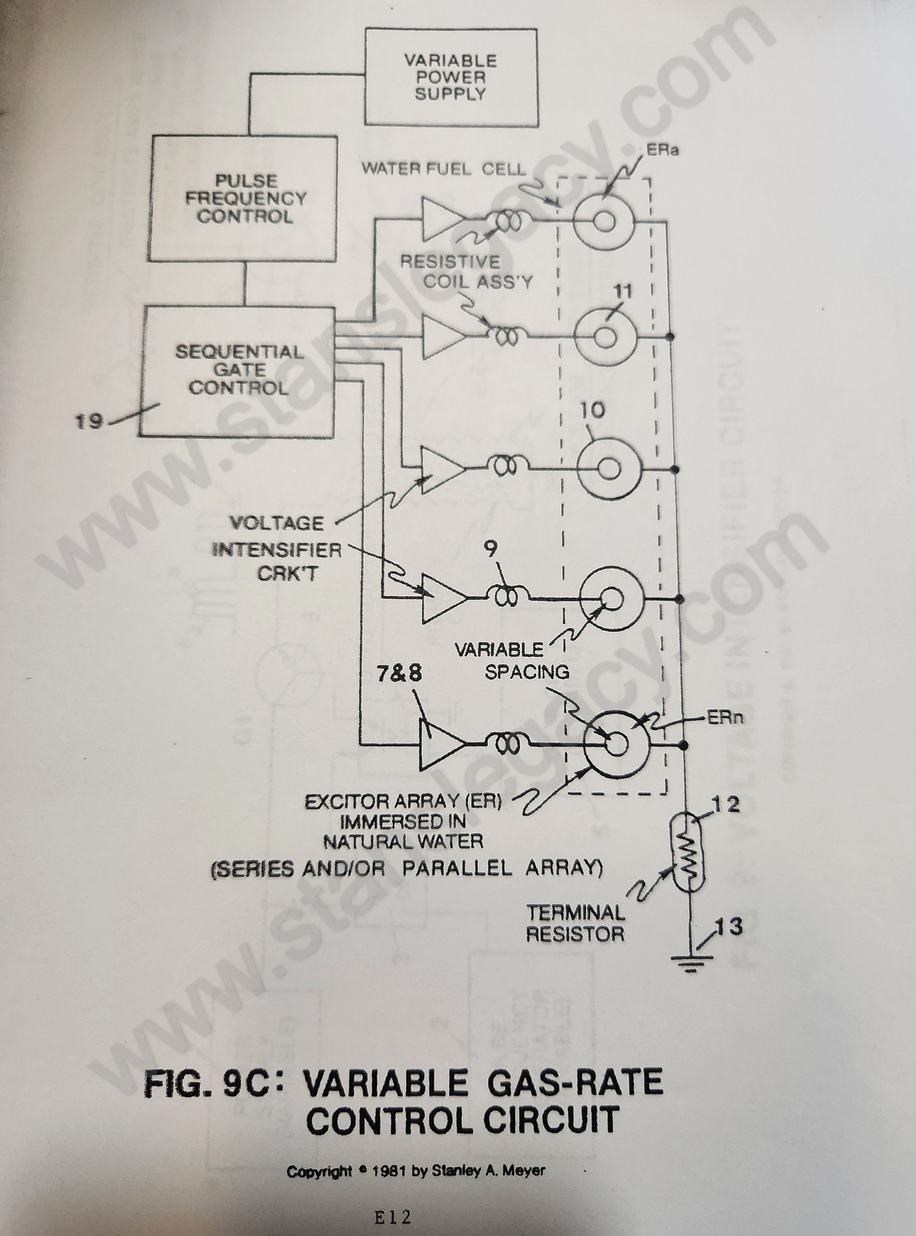 |
Voltage Attenuation Circuit |
| 9D Voltage Chamber · ETM E13 | 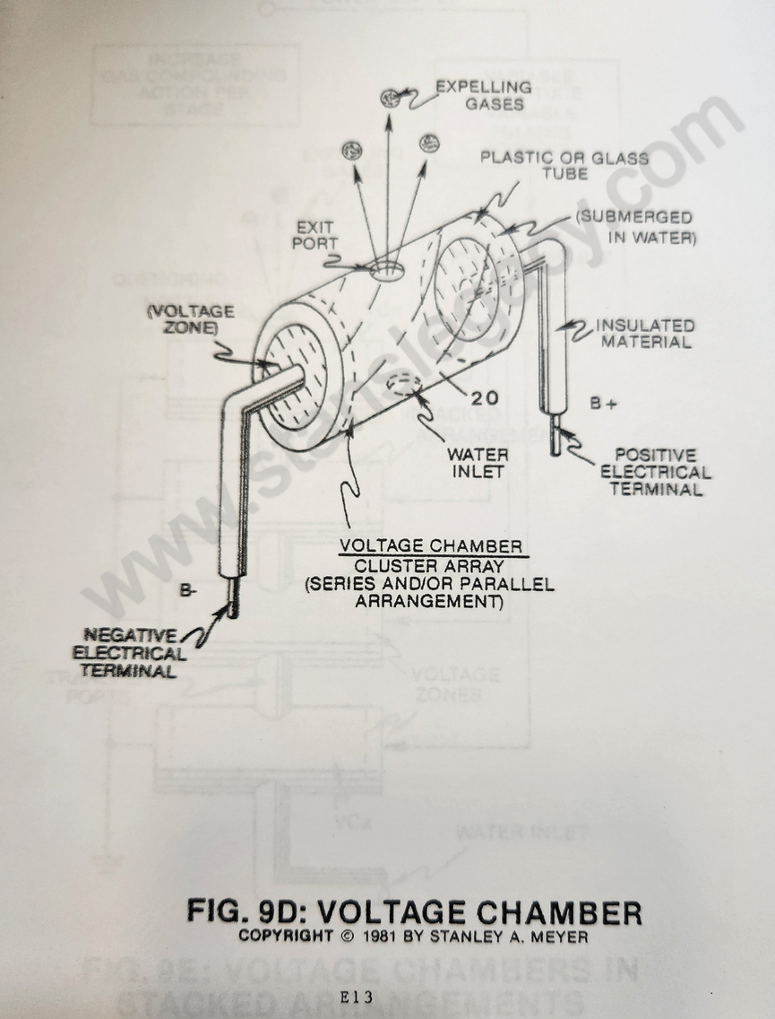 |
Voltage Attenuation Circuit; also Resonant Cavity Mode of Operability |
| 9E Voltage Chambers in Stacked Arrangements · ETM E14 | 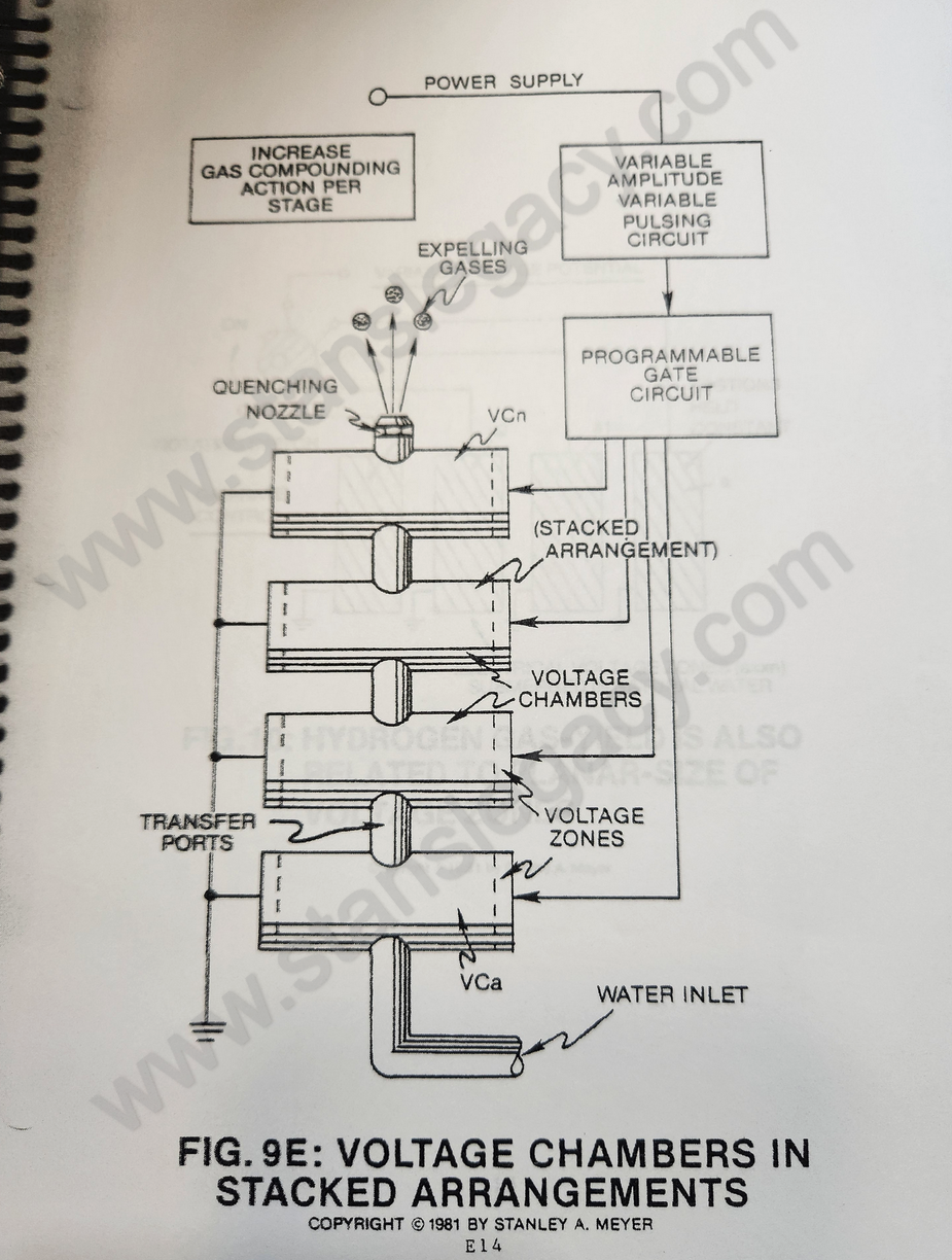 |
Voltage Attenuation Circuit |
| 10 Hydrogen Gas-Yield Is Also Related to Planar Size of Voltage Zones · ETM E15 | 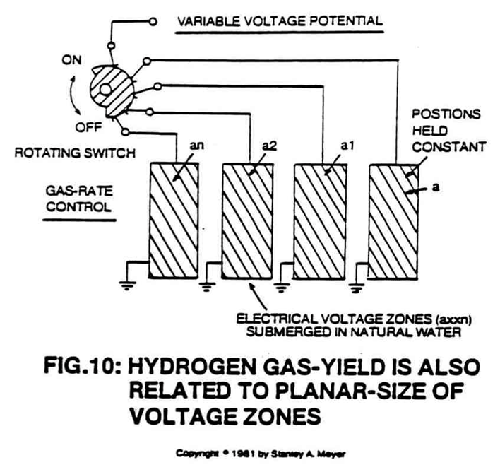 |
Operational Parameters of the Invention |
The voltage intensifier circuits and their boards
| Figure | Drawing | In the archive |
|---|---|---|
| 9XA Variable Voltage Pulsing Circuit Schematic · ETM E33 | 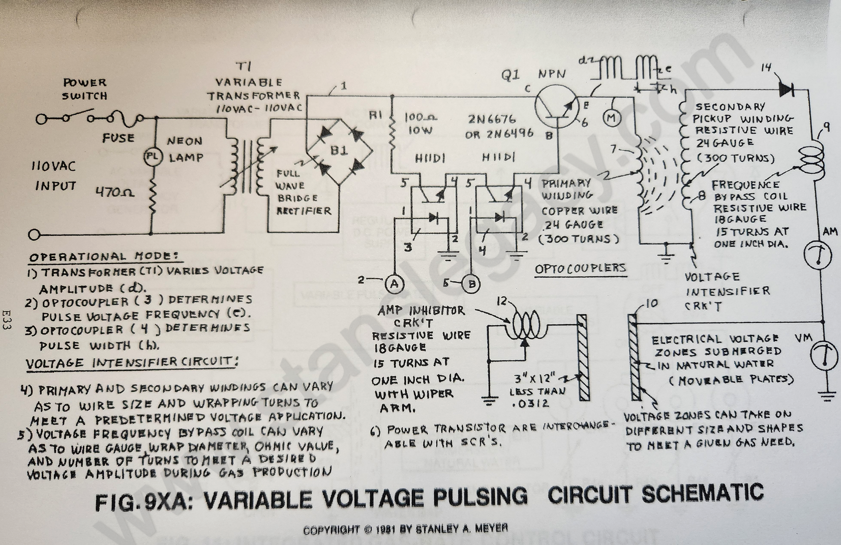 |
SINGLE VOLTAGE RESONANT "Q" |
| 9XAA Variable Voltage Pulsing Circuit Component Wiring Harness · ETM E34 | Not held | |
| 9XAA1 Voltage Intensifier Assembly · ETM E35 | 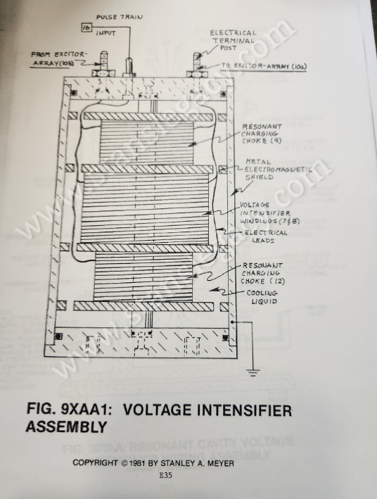 |
Hydrogen Gas Gun Technology |
| 9XAA2 Variable Voltage Pulsing Circuit Printed Circuit Board · ETM E36 | Not held | |
| 9XAA3 Variable Voltage Pulsing Circuit Component Layout · ETM E37 | Not held | |
| 9XAA4 Variable Voltage Pulsing Circuit Wiring Harness · ETM E38 | Not held | |
| 9XB Variable Pulse Voltage Frequency Generator · ETM E39 | Not held | |
| 9XBB Variable Pulse Voltage Frequency Generator Printed Circuit Board · ETM E40 | Not held | |
| 9XBB2 Variable Pulse Voltage Frequency Generator Wiring Harness · ETM E42 | Not held | |
| 9XC Variable Gate Circuit Schematic · ETM E43 | Not held | |
| 9XCC Variable Gate Printed Circuit Board · ETM E44 | Not held | |
| 9XCC1 Variable Gate Component Layout · ETM E45 | Not held | |
| 9XCC2 Variable Gate Wiring Harness · ETM E46 | Not held | |
| 9XD Voltage Regulator Circuit Schematic · ETM E47 | Not held | |
| 9XDD Voltage Regulator Printed Circuit Board · ETM E48 | Not held | |
| 9XDD1 Voltage Regulator Component Layout · ETM E49 | Not held | |
| 9XDD2 Voltage Regulator Wiring Harness · ETM E50 | Not held | |
| 9XE Sequential Gate Circuit Schematic · ETM E51 | Not held | |
| 9XEE Sequential Gate Printed Circuit Board · ETM E52 | Not held | |
| 9XEE1 Sequential Gate Component Layout · ETM E53 | Not held | |
| 9XEE2 Sequential Gate Wiring Harness · ETM E54 | Not held | |
| 9XA/E Cage Wiring Harness · ETM E55 | Not held | |
| 9XF Toroidal Voltage Intensifier Circuit Schematic · ETM E56 | 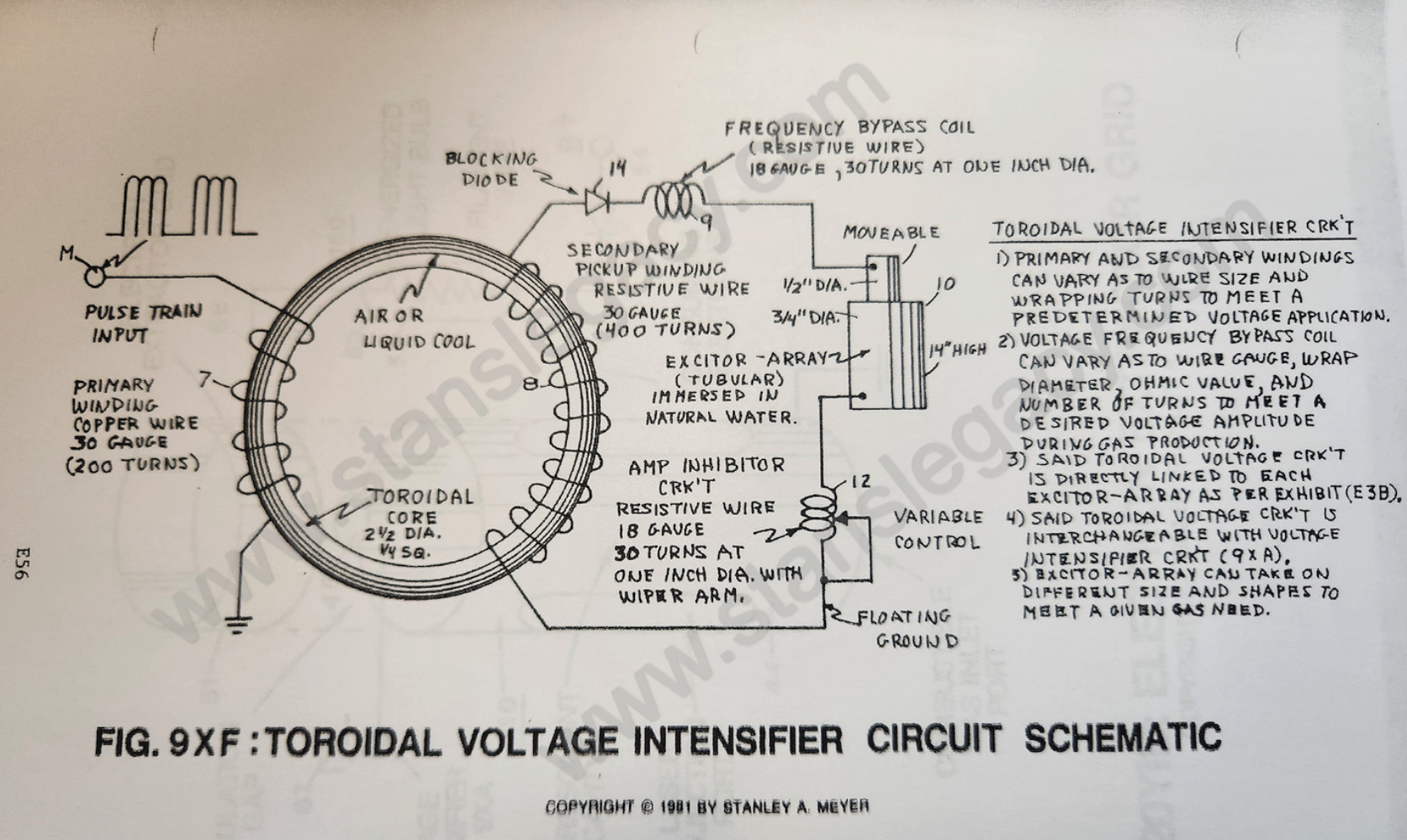 |
Voltage Attenuation Circuit; also Resonant Cavity Mode of Operability |
| 9XG Rotary Voltage Intensifier Circuit Schematic · ETM E57 | 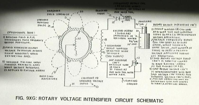 |
Resonant Cavity Mode of Operability; also Voltage Attenuation Circuit |
The resonant cavity
| Figure | Drawing | In the archive |
|---|---|---|
| 12 Electrical Voltage Zones (B−/B+) Forming a Resonant Cavity · ETM F2 | 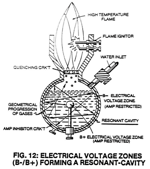 |
Spin Off Technology; also Mega Watt Gas Yield, SINGLE VOLTAGE RESONANT "Q" |
| 13 Longitudinal Resonant Cavity · ETM F3 | 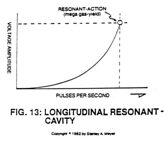 |
Mega Watt Gas Yield; also Resonant Cavity Mode of Operability |
| 14 Spherical Resonant Cavity · ETM F3 | 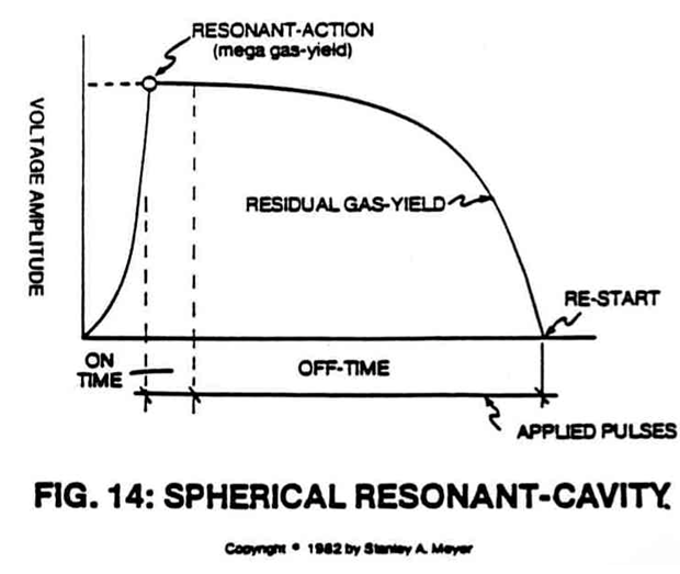 |
Mega Watt Gas Yield; also Resonant Cavity Mode of Operability |
| 15 Spherical Resonant Cavity · ETM F4 | 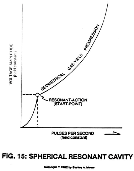 |
Mega Watt Gas Yield; also Resonant Cavity Mode of Operability |
| 16 Variable Voltage Amplitude Controls Resonant-Action Output · ETM F5 | 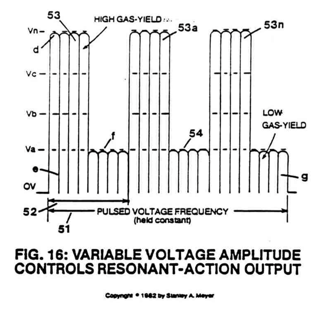 |
Operational Parameters of the Invention; also Spin Off Technology, Resonant Cavity |
| 16A Applied Voltage to Resonant Cavity · ETM F6 | 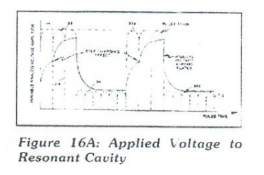 |
Voltage Attenuation Circuit; also SINGLE VOLTAGE RESONANT "Q", DUAL VOLTAGE RESONANT "Q", Dual Voltage Resonant "Q" - Part 2 |
| 17 Resonant Cavities Forming the Water Vessel · ETM F9 | 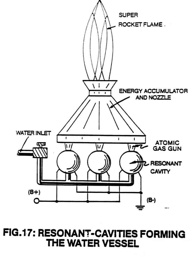 |
Spin Off Technology; also Mega Watt Gas Yield |
| 18 Photon Energy Aids Resonant Action · ETM F10 | 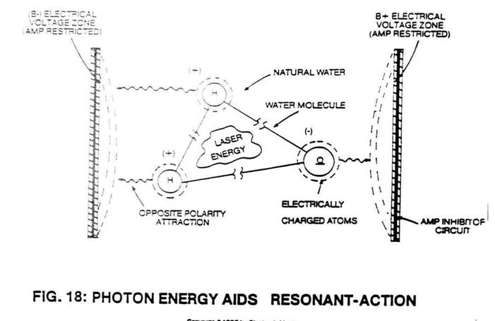 |
Mega Watt Gas Yield |
| 19 Laser Injected Resonant Cavity · ETM F11 | 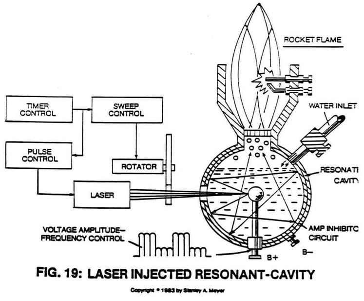 |
Spin Off Technology; also Mega Watt Gas Yield |
| 20C Resonant Cavity Dual-Voltage Pulsing Circuit · ETM F16 | 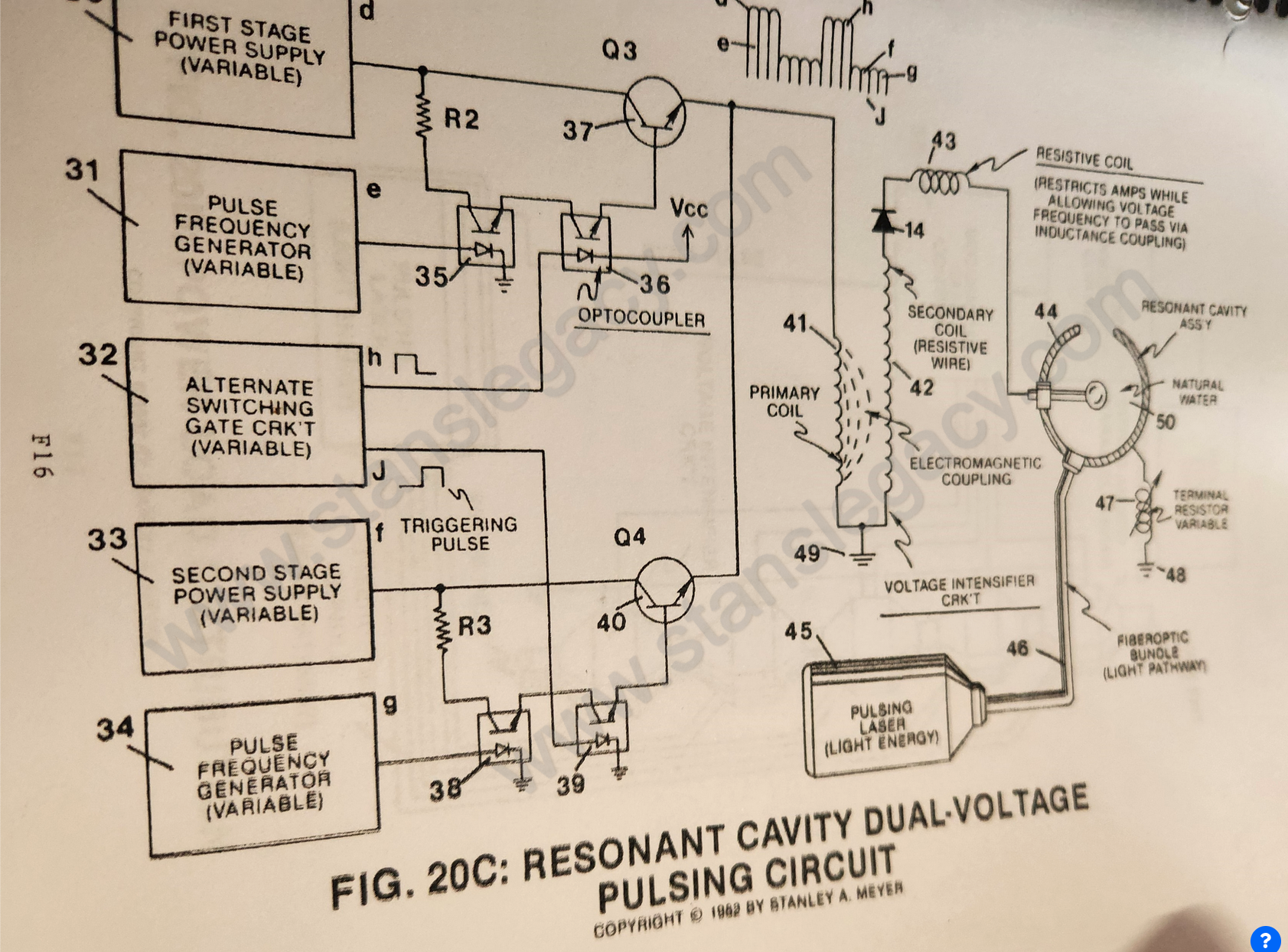 |
Resonant Cavity. A second, different drawing is also numbered 20C; see below. |
| 20D Power Load Distribution · ETM F17 | 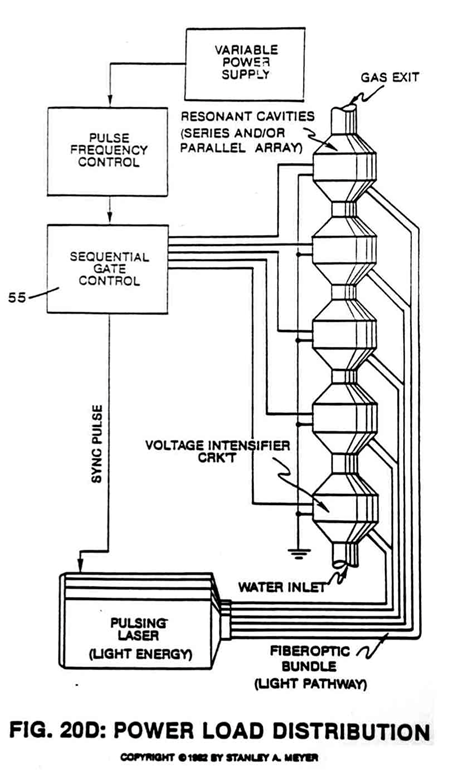 |
Mega Watt Gas Yield; also Resonant Cavity |
| 20E Controlled Energy-Yield from Water Atoms · ETM G2 | Not held | |
| 20F Hydrogen Fracturing Process · ETM G3 | 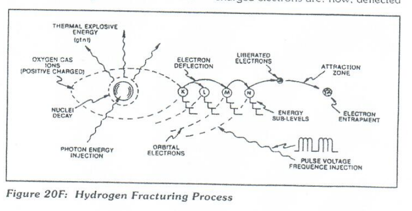 |
Hydrogen Gas Gun Technology |
| 20FA Hydrogen Fracturing Process Prior to Gas Ignition · ETM G4 | Not held | |
| 20FB (no title in the index) | Not held | |
| 20FC Optical Thermal Lens Assembly · ETM G6 | Not held | |
| 20G Gas Resonant Cavity · ETM G7 | 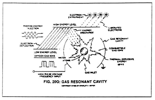 |
Hydrogen Gas Gun Technology |
| 20H Gas Injector Fuel Cell · ETM G8 | 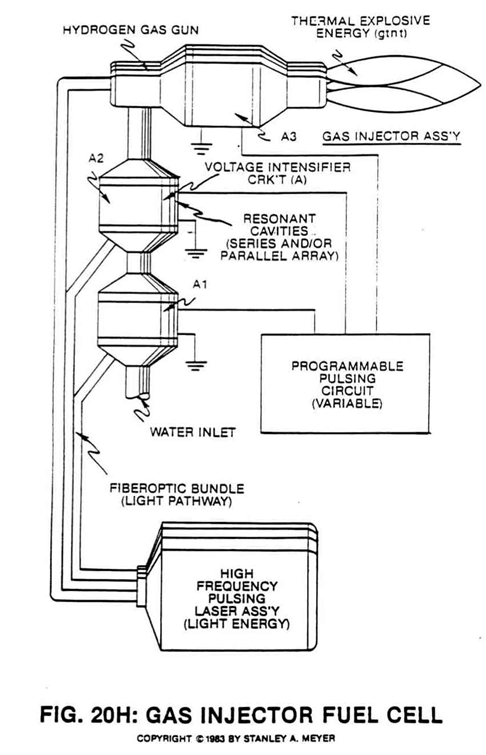 |
Mega Watt Gas Yield |
| 20JX Gas Resonant Cavity · ETM G29 | 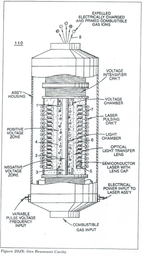 |
Hydrogen Gas Gun Technology |
The resonant-cavity boards and the hydrogen gas gun
| Figure | Drawing | In the archive |
|---|---|---|
| 20YBB Variable Pulse Voltage Wiring Harness · ETM F29 | Not held | |
| 20YC Variable Alternate Switching Gate Circuit Schematic · ETM F30 | Not held | |
| 20YCC Variable Gate Wiring Harness · ETM F31 | Not held | |
| 20YD Gate Driver Circuit · ETM F32 | Not held | |
| 20YDD Gate Driver Printed Circuit Board · ETM F33 | Not held | |
| 20YDD1 Cascaded Gate Switch Printed Circuit Board · ETM F34 | Not held | |
| 20YE Variable Sequential Gate Circuit to Resonant Cavity Array Circuit · ETM F36 | Not held | |
| 20YEE Sequential Gate Printed Circuit Board · ETM F36 | Not held | |
| 20YEE1 Variable Sequential Gate Component Layout · ETM F37 | Not held | |
| 20YEE2 Variable Sequential Gate Wiring Harness · ETM F38 | Not held | |
| 20YF Voltage Regulator Circuit Schematic · ETM F39 | Not held | |
| 20YFF Voltage Regulator Wiring Harness · ETM F40 | Not held | |
| 20YG Voltage Intensifier Circuit Schematic (Resonant Cavity) · ETM F41 | Not held | |
| 20YH Rotary Voltage Intensifier Circuit Schematic (Resonant Cavity) · ETM F42 | Not held | |
| 20YJ Photon or Light Injector Module Schematic · ETM F43 | Not held | |
| 20YJJ Light Injector Module Assembly · ETM F44 | Not held | |
| 20YJJ1 Light Injector Module Printed Circuit Board · ETM F45 | Not held | |
| 20YJJ2 Light Injector Module Component Layout · ETM F46 | Not held | |
| 20YJJ3 Variable Pulse Voltage Wiring Harness · ETM F47 | Not held | |
| 20YA/J Cage Wiring Harness · ETM F48 | Not held | |
| 20YI Voltage Level Switching Printed Circuit Board · ETM G34 | 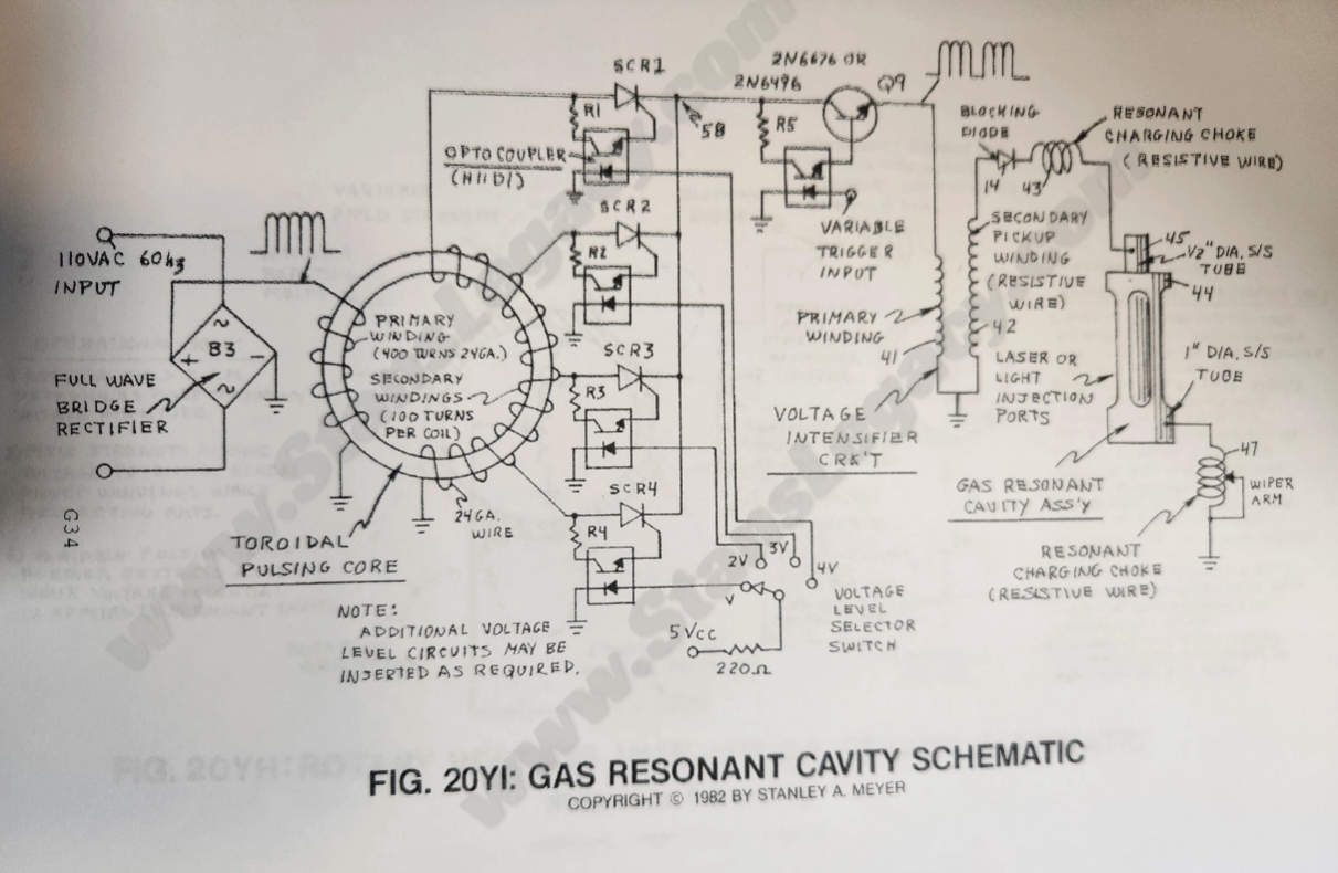 |
Hydrogen Gas Gun Technology. The drawing is titled Gas Resonant Cavity Schematic; the index gives that title to 20YIA. |
| 20YIA Gas Resonant Cavity Schematic · ETM G35 | 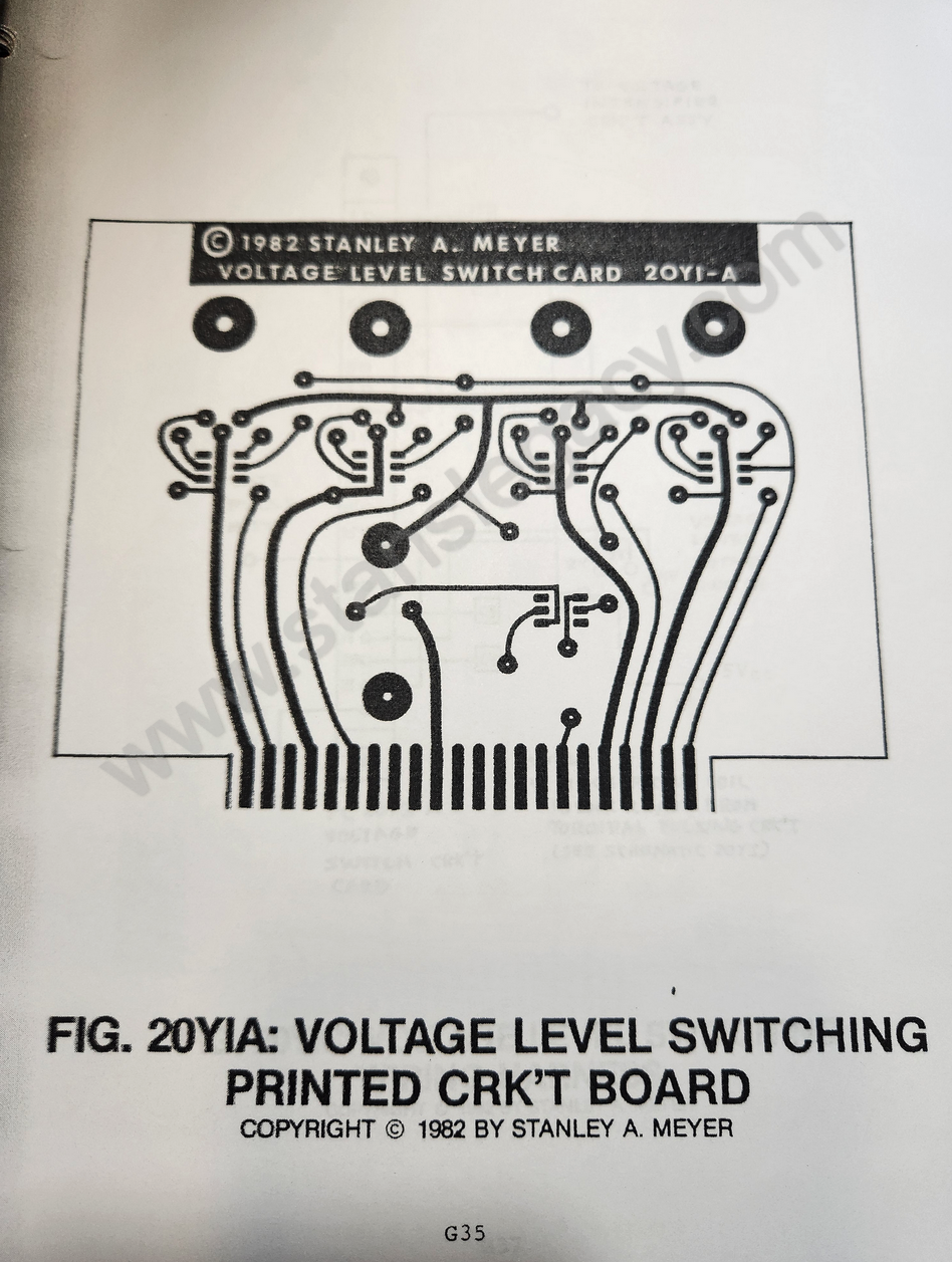 |
Hydrogen Gas Gun Technology. The drawing is titled Voltage Level Switching Printed Crk't Board; the index gives that title to 20YI. |
| 20YIB Voltage Level Switching Component Layout · ETM G36 | 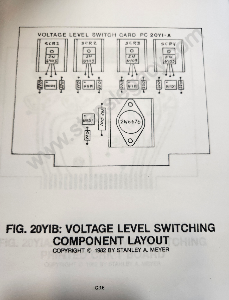 |
Hydrogen Gas Gun Technology |
| 20YIC Voltage Level Switching Wiring Harness · ETM G37 | 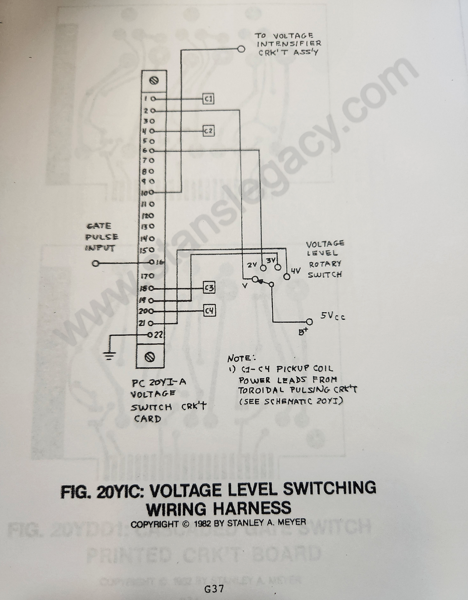 |
Hydrogen Gas Gun Technology |
| 20YID Electron Extractor Grid · ETM G39 | 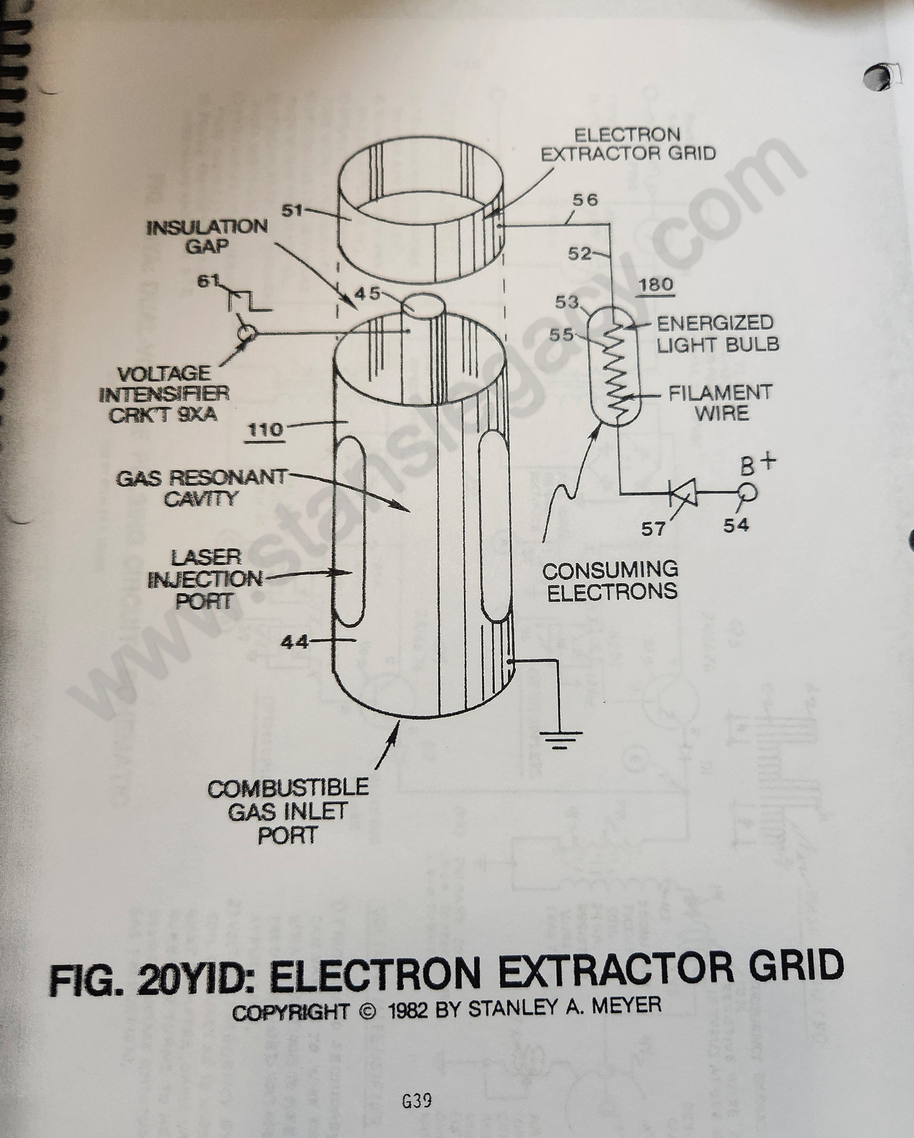 |
Hydrogen Gas Gun Technology |
| 20YIE Electron Extraction Schematic · ETM G40 | 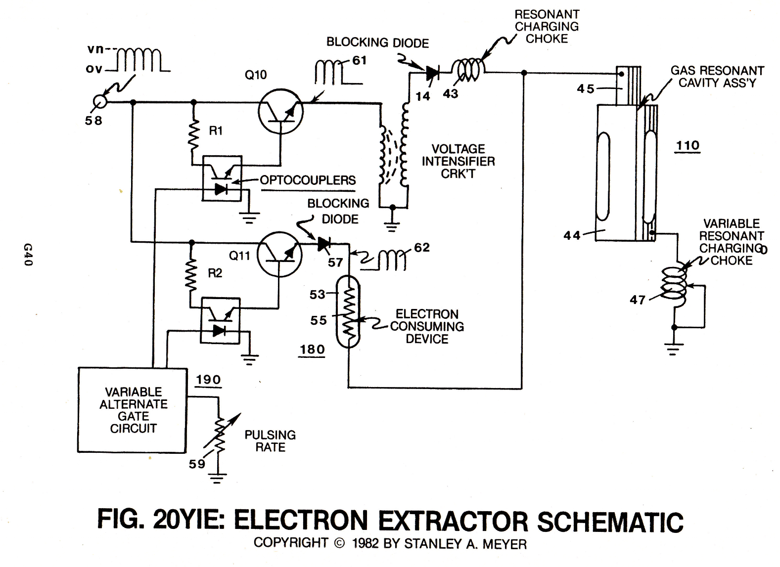 |
Hydrogen Gas Gun Technology |
| 20Z/C Cage Wiring Harness · ETM G23 | Not held |
Using the gas
| Figure | Drawing | In the archive |
|---|---|---|
| 22 Water Fuel Cell Retrofitted to an Internal Combustion Engine · ETM H4 | 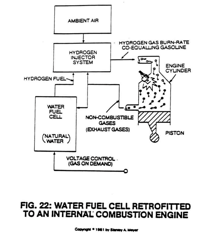 |
Hydrogen Gas Utilization; also Catalytic Block Assembly |
| 23 Types of Land Vehicle Fuels · ETM H5 | 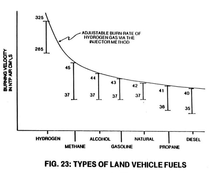 |
Spin Off Technology; also Fuel Cell Economics, Hydrogen Gas Utilization, Catalytic Block Assembly |
| 24 Rendering Hydrogen Safer than Natural Gas · ETM H6 | 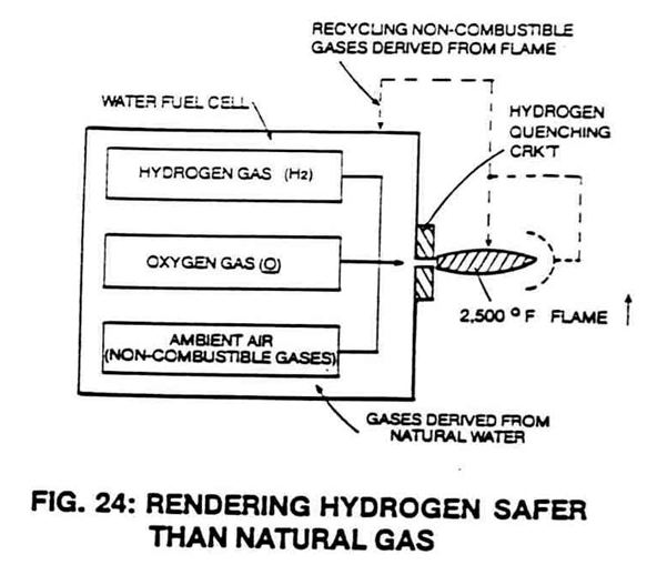 |
Hydrogen Gas Utilization; also Fuel Cell Economics, Spin Off Technology |
| 24SA Catalytic Block Assembly · ETM H13 | 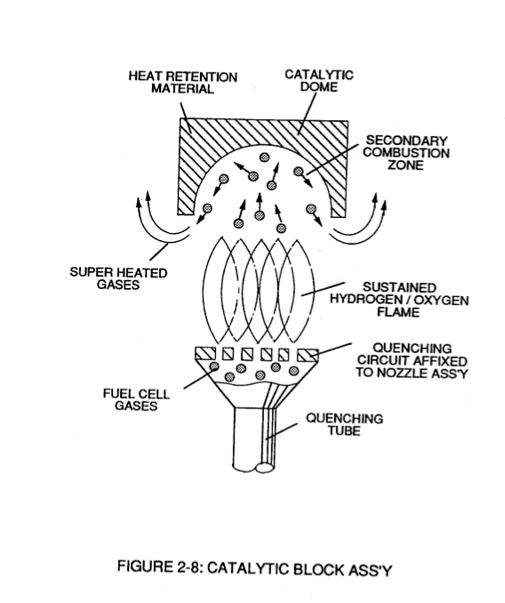 |
Catalytic Block Assembly. Possibly: the archive's drawing is numbered Figure 2-8, "Catalytic Block Ass'y". |
| 24SB Quenching Nozzle · ETM H14 | Not held | |
| 24SC Recycling Flame Gases · ETM H15 | Not held | |
| 24SD Preventing Gas Ignition · ETM H16 | Not held | |
| 25 Quenching Tube Allows Hydrogen to Be Distributed without Spark Ignition · ETM H7 | 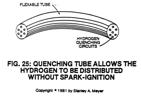 |
Fuel Cell Economics |
The electrical particle generator
| Figure | Drawing | In the archive |
|---|---|---|
| 26 EPG Principle Allowing Permanently Magnetized Fluid Medium to Pass through a Pickup Coil · ETM J4 | 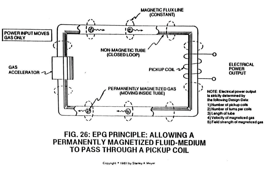 |
Dynamic Ways To Produce Electricity; also Spin Off Technology, ELECTRICAL PARTICLE GENERATOR |
| 26A Attenuating Gas Field · ETM J5 | 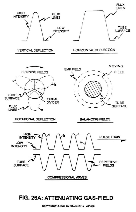 |
Dynamic Ways To Produce Electricity; also ELECTRICAL PARTICLE GENERATOR |
| 26B Pickup Coil Configurations · ETM J6 | 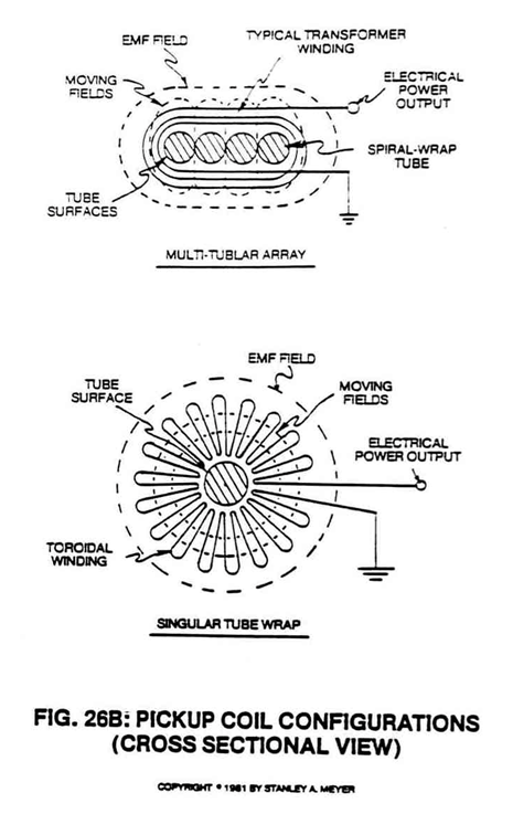 |
Dynamic Ways To Produce Electricity; also ELECTRICAL PARTICLE GENERATOR |
| 26C Multi-Tier EPG Electrical Generator · ETM J7 | 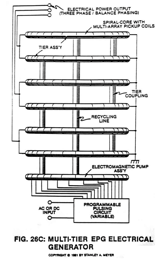 |
Dynamic Ways To Produce Electricity; also ELECTRICAL PARTICLE GENERATOR |
| 26D Electromagnetic Pump Assembly (EPG) · ETM J8 | 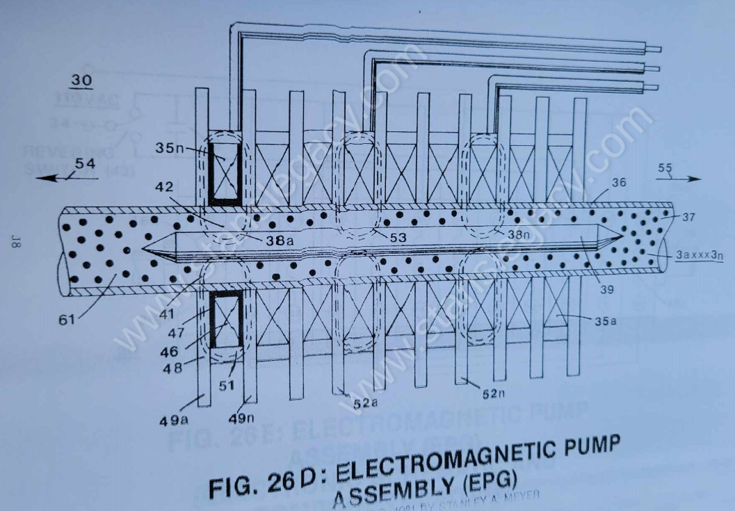 |
ELECTRICAL PARTICLE GENERATOR |
| 26E Electromagnetic Pump Assembly (EPG) Electronic Schematic and Component Layout | 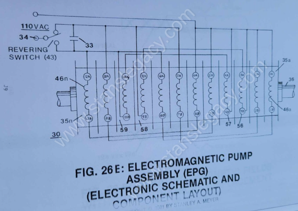 |
ELECTRICAL PARTICLE GENERATOR |
| 26F Rotating Magnetic Fields without Mechanical Displacement | 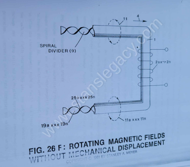 |
ELECTRICAL PARTICLE GENERATOR |
| 26ZA Opposing Magnetic Fields · ETM J32 | 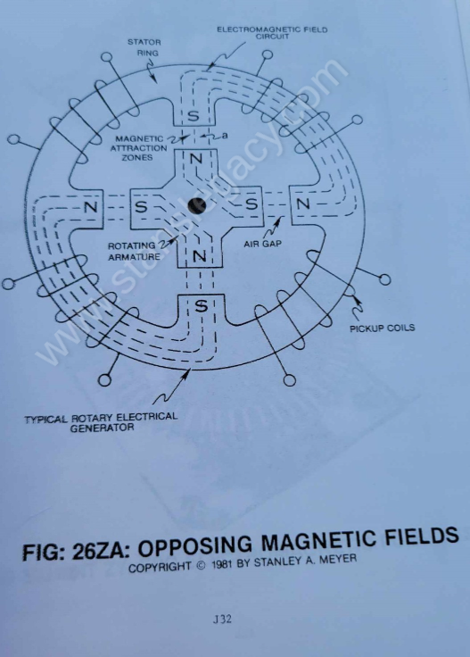 |
ELECTRICAL PARTICLE GENERATOR |
| 27 EPG Mechanical Drive Gas Accelerator · ETM J12 | 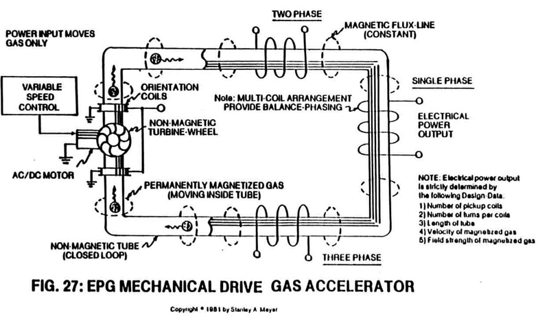 |
Dynamic Ways To Produce Electricity; also Spin Off Technology |
| 28 EPG Electrical Magnetic Gas Accelerator · ETM J13 | 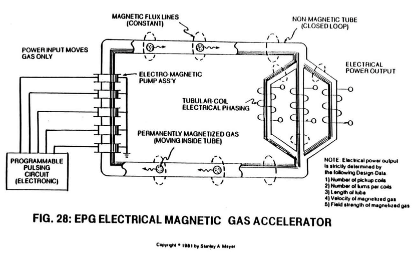 |
Dynamic Ways To Produce Electricity; also Spin Off Technology |
| 29 EPG Photon Drive Accelerator · ETM J14 | 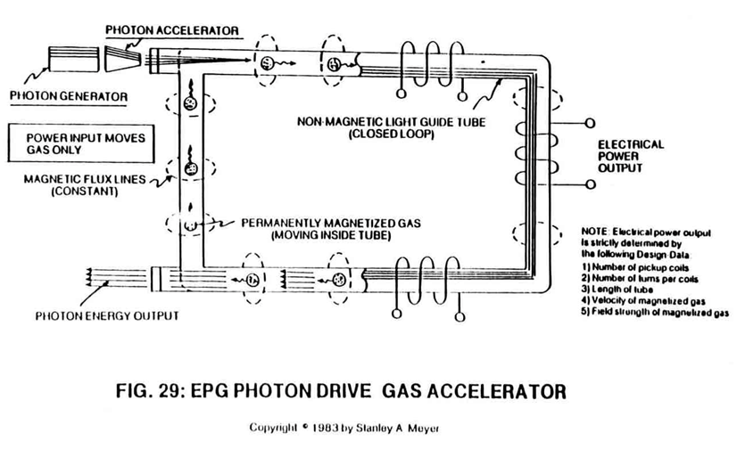 |
Dynamic Ways To Produce Electricity; also Spin Off Technology |
| 30 EPG Magnetic Field Spin Generator · ETM J15 | 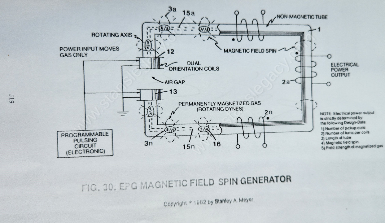 |
MAGNETIC SPIN GENERATOR; also Dynamic Ways To Produce Electricity, Spin Off Technology |
| 30ZC Magnetic Spin Generator (Quiescent State) · ETM J37 | 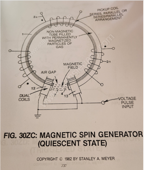 |
MAGNETIC SPIN GENERATOR |
| 30ZD Magnetic Spin Generator (Triggered State) · ETM J38 | 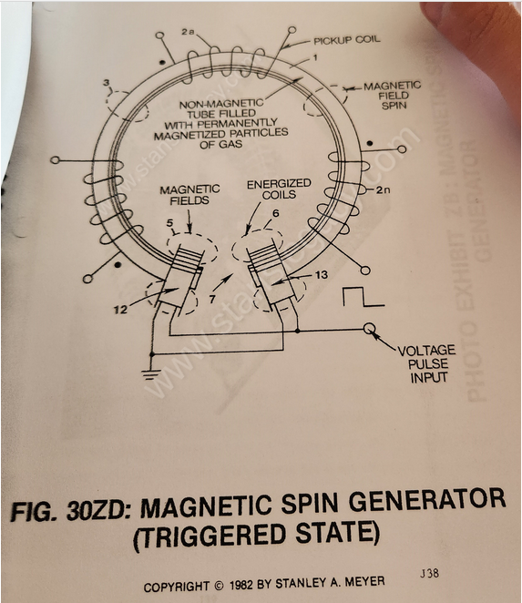 |
MAGNETIC SPIN GENERATOR |
The steam resonator and the generators
| Figure | Drawing | In the archive |
|---|---|---|
| 32QX Steam Resonator Schematic · ETM K21 | 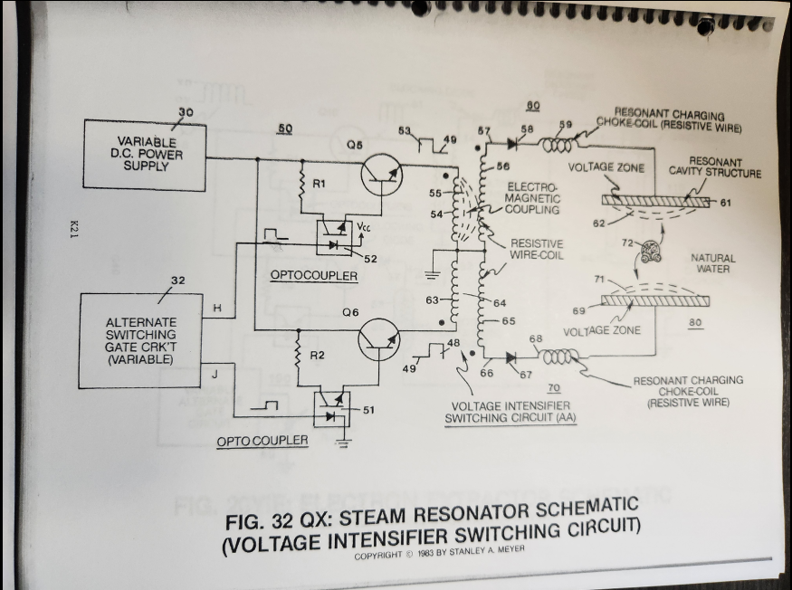 |
Steam Resonator |
| 37 Internal Combustion Electrical Generator · ETM K12 | 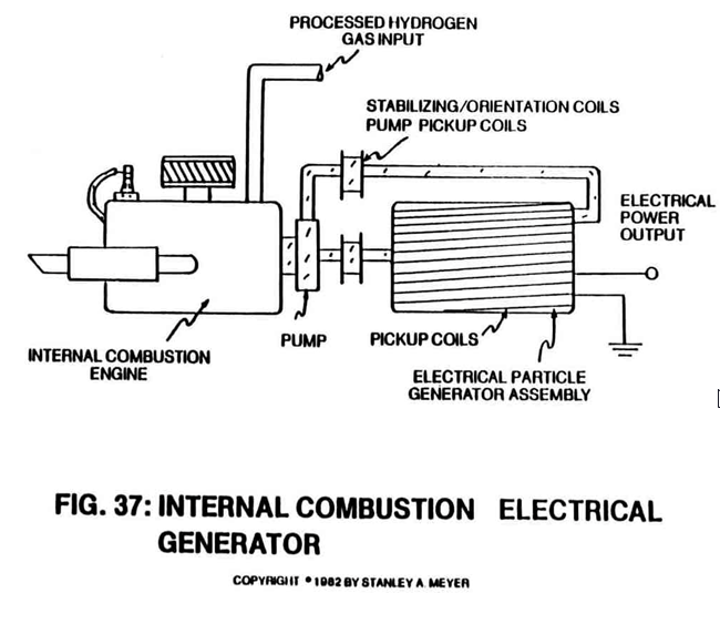 |
Dynamic Ways To Produce Electricity; also Spin Off Technology |
Exhibits
| Figure | Drawing | In the archive |
|---|---|---|
| AZ (no title in the index) | Not held | |
| E1 Variable Spacing · ETM E58 | Not held | |
| EA1 Photo: Variable Plate Spacing Test Unit · ETM E59 | Not held | |
| E2 Tubular Cluster-Array · ETM E60 | Not held | |
| E2A Photo: Cluster-Array Test Unit · ETM E61 | 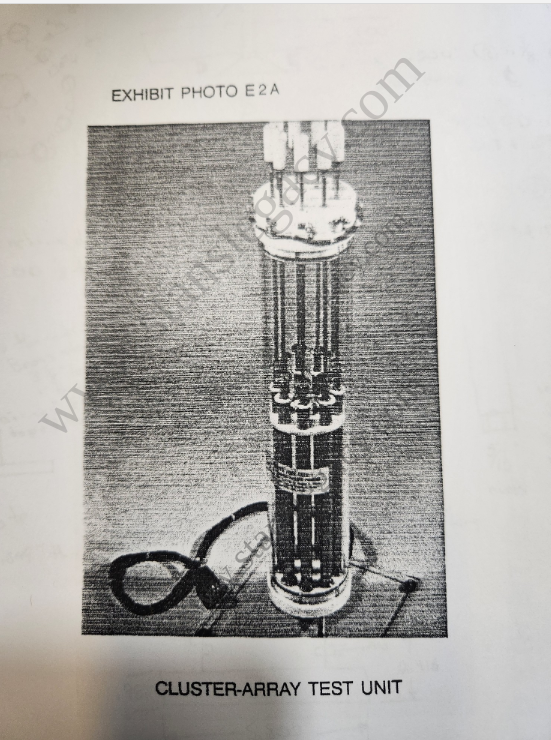 |
Exhibit E 2 A |
| E3 Photo: Electrical Polarization Process · ETM E62 | 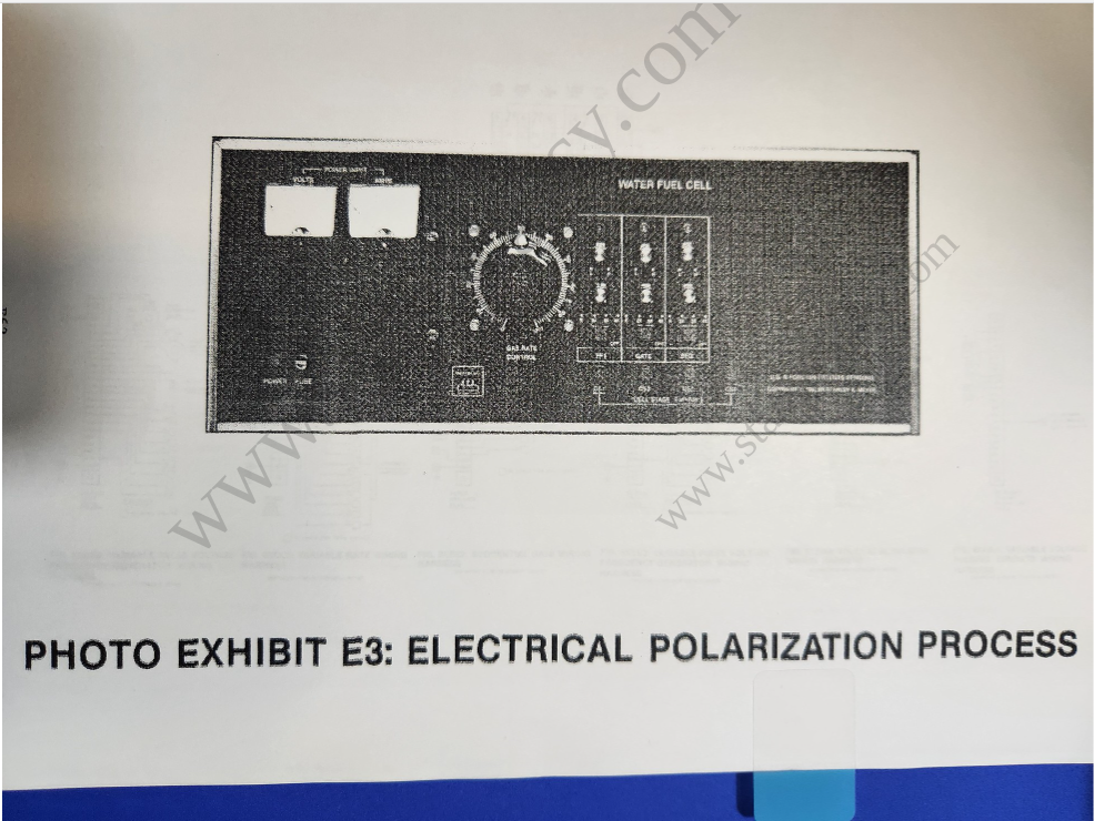 |
Exhibit E3 |
| E4 Longitudinal Resonant-Cavity · ETM F49 | 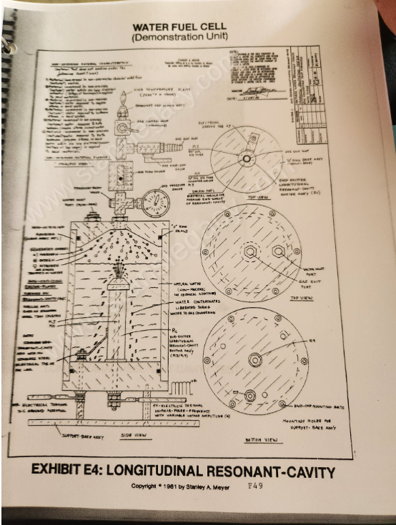 |
Exhibit E 4 |
| E5 Spherical Resonant Cavity · ETM F51 | 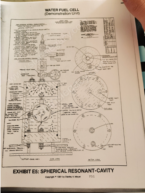 |
Exhibit E 5 |
| E9 Photo: Multi-Tier Resonant Cavity Assembly · ETM F56 | 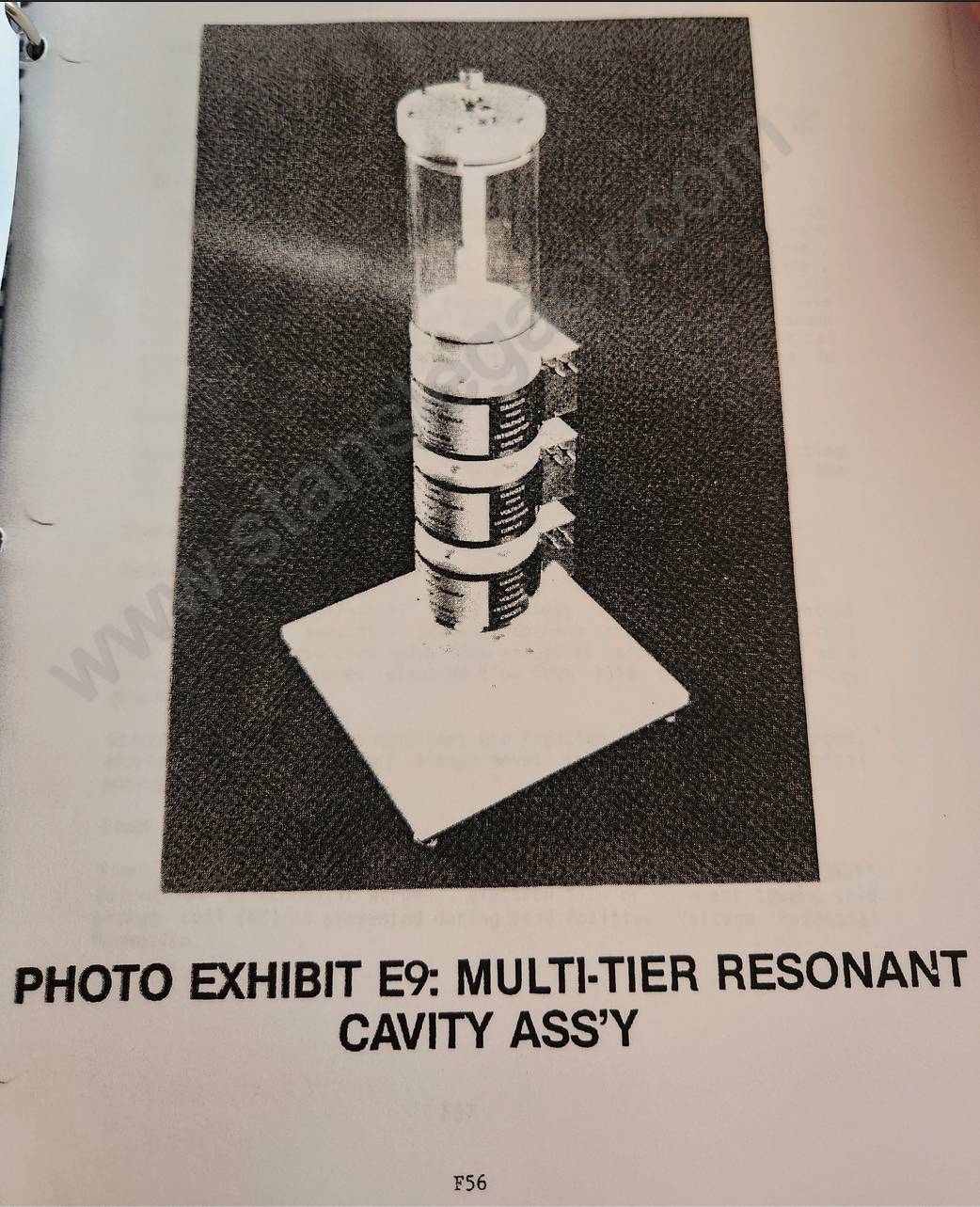 |
Exhibit E 9 |
| ZX Photo: EPG Mechanical Drive Assembly · ETM J33 | 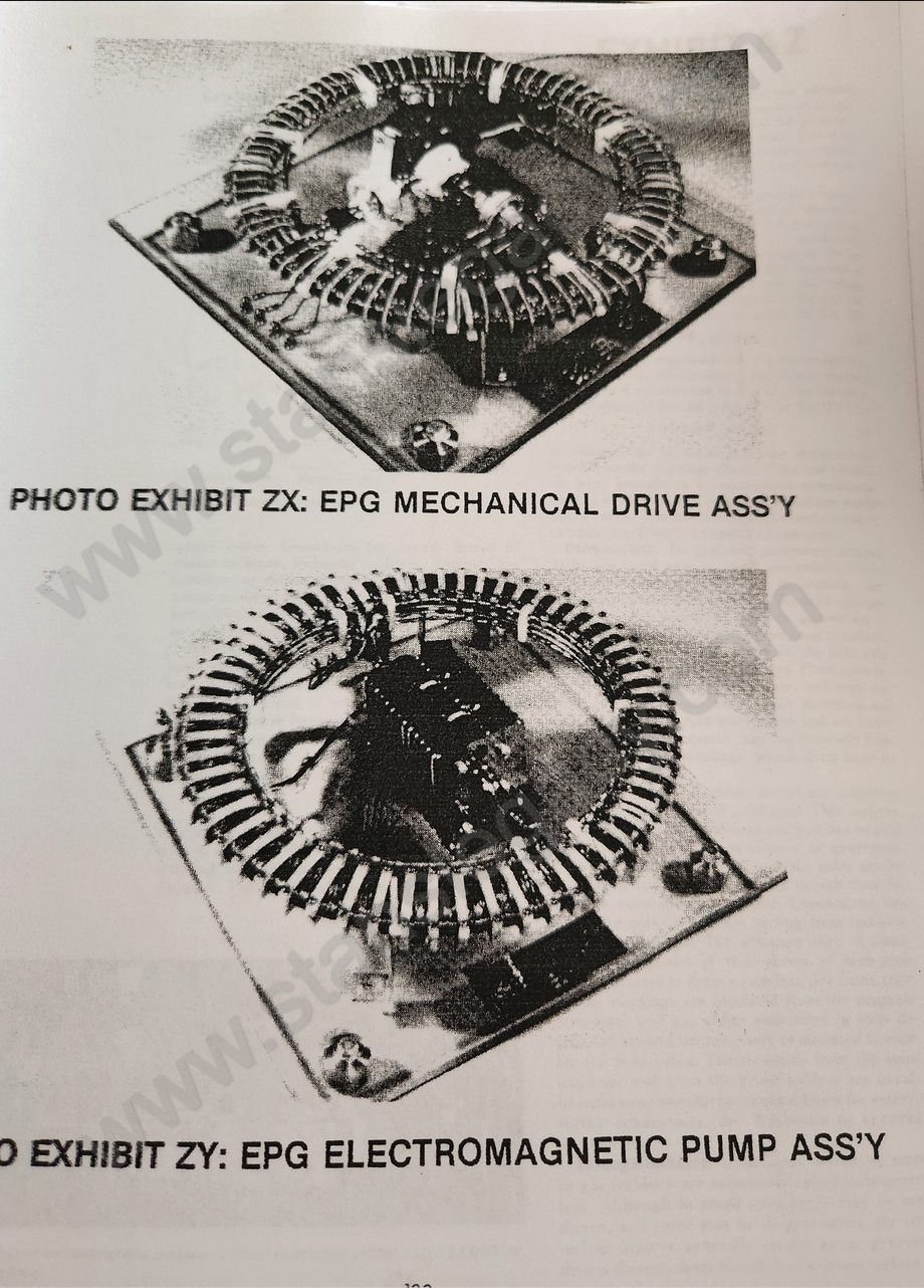 |
Exhibit ZX & ZY. Photographed on one page with ZY. |
| ZY Photo: EPG Electromagnetic Pump Assembly · ETM J33 | |
Exhibit ZX & ZY. Photographed on one page with ZX. |
In the archive but not in the index
Drawings on the manual's pages that the 2014 index does not list. The title is the one printed on the drawing.
| Figure | Drawing | In the archive |
|---|---|---|
| 6 Hydrogen Gas-Yield Is Further Increased by Narrowing Water-Gap | 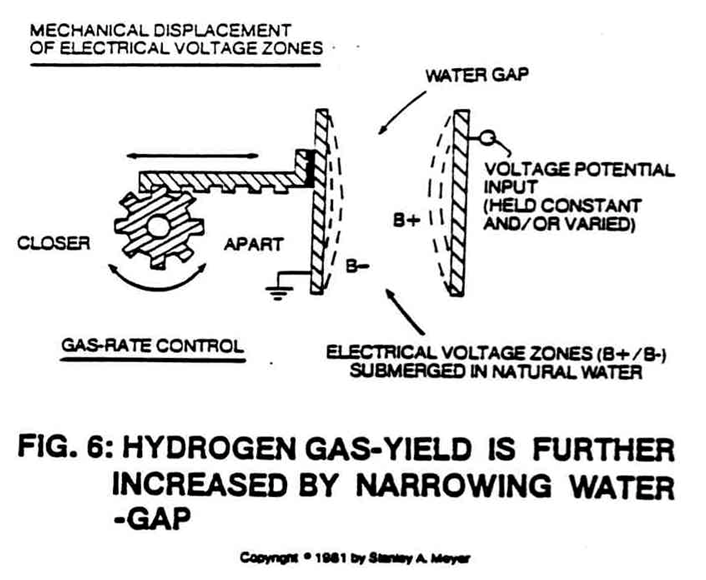 |
Operational Parameters of the Invention |
| 6B (no title on the drawing) | 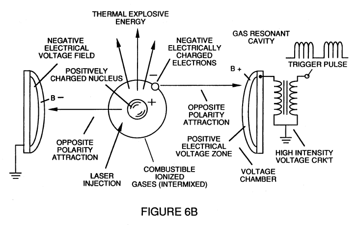 |
Voltage Attenuation Circuit |
| 11 Integrated Gas-Rate Control Circuit (Generating Hydrogen Gas on Demand) | 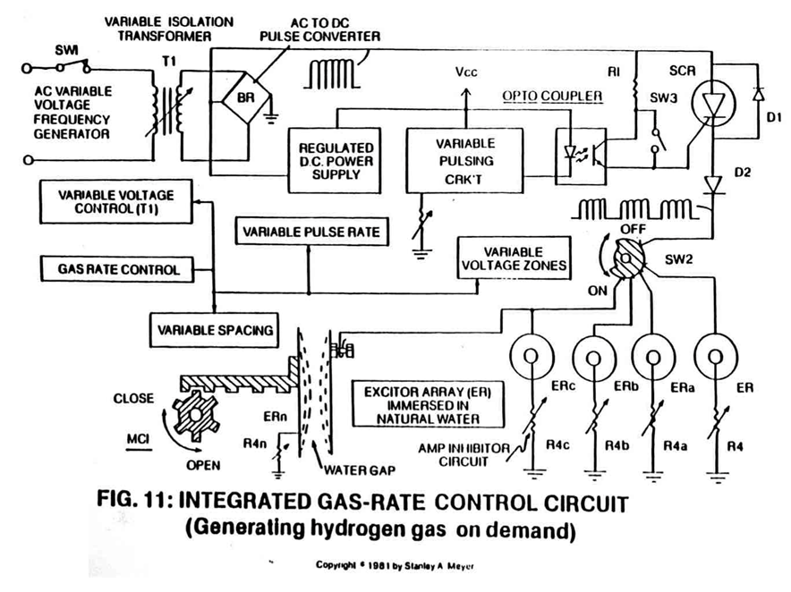 |
Operational Parameters of the Invention |
| 11A Variable Pulse-Voltage Frequency Generator (Generating Hydrogen Gas on Demand) | 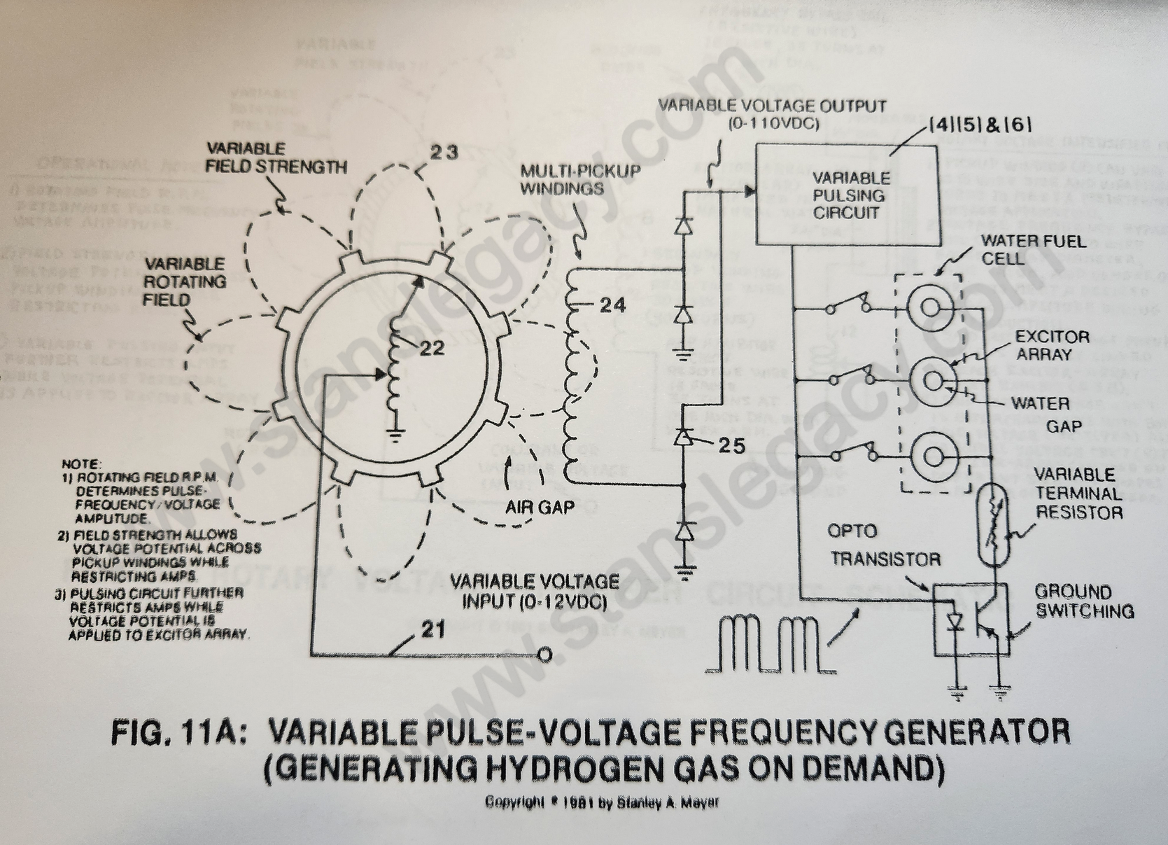 |
Voltage Attenuation Circuit; also Operational Parameters of the Invention |
| 20 Atom Injected Resonant-Cavity (Interlocking Modules) | 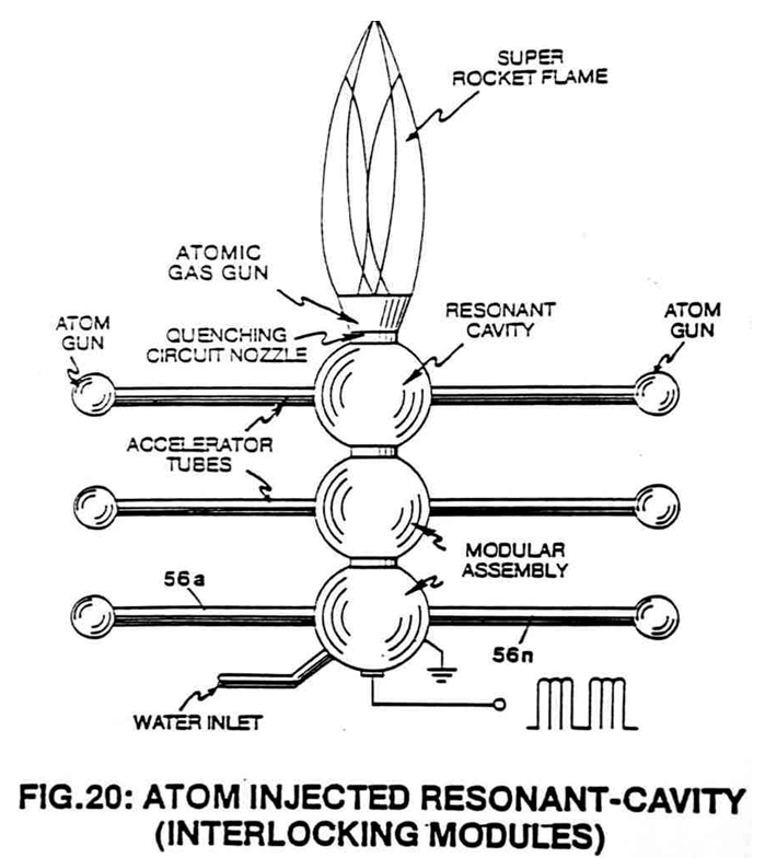 |
Mega Watt Gas Yield; also Spin Off Technology |
| 20A Gas Accelerator Tube | 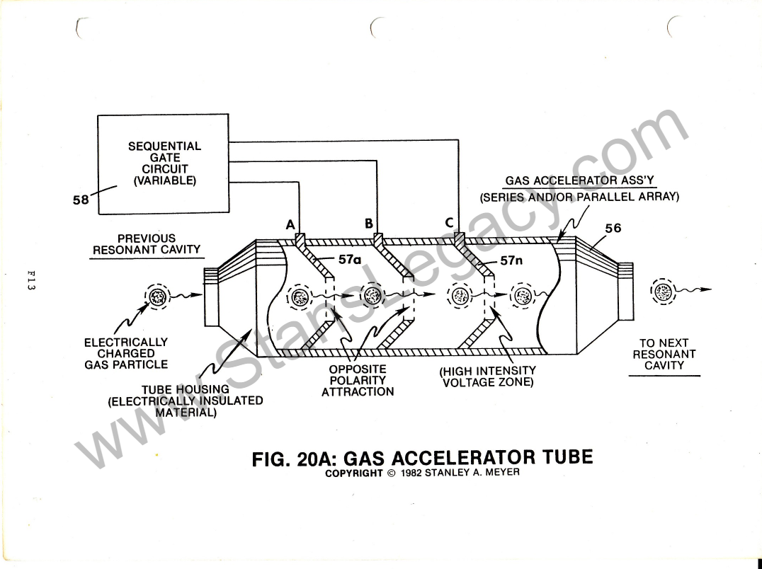 |
Resonant Cavity Mode of Operability |
| 20B Atom Injected Resonant Cavity (Spoke Wheel Configuration) | 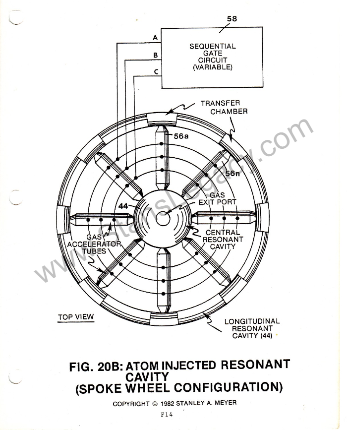 |
Resonant Cavity Mode of Operability; also Dynamic Ways To Produce Electricity |
| 20C Voltage Intensifier Circuit | 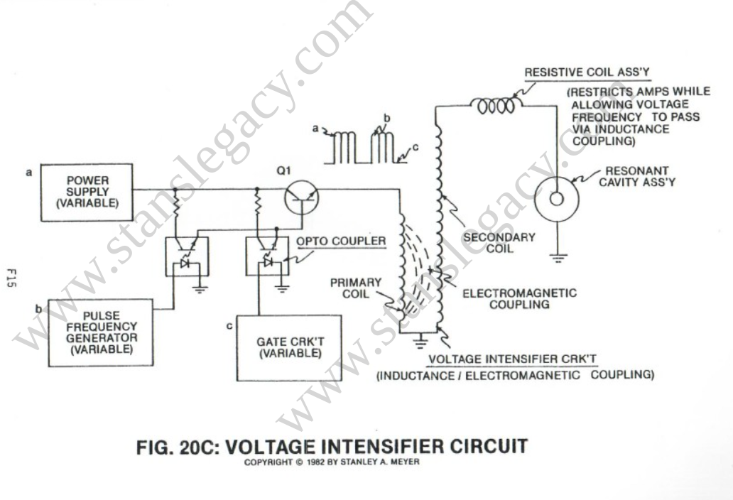 |
Resonant Cavity Mode of Operability; also ELECTRICAL POLARIZATION GENERATOR |
| 20YAA Resonant Cavity Voltage Intensifier Wiring Assembly | 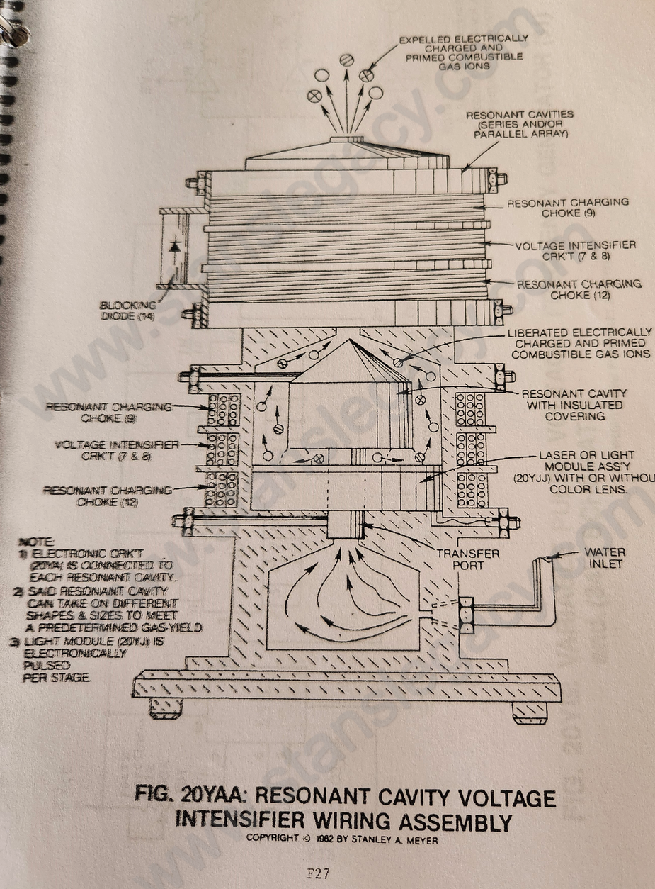 |
Resonant Cavity Mode of Operability; also Dual Voltage Resonant "Q" - Part 2 |
| 21 The Water Fuel Cell Can Be Directly Retrofitted to Existing Energy-Consuming Devices without System-Change | 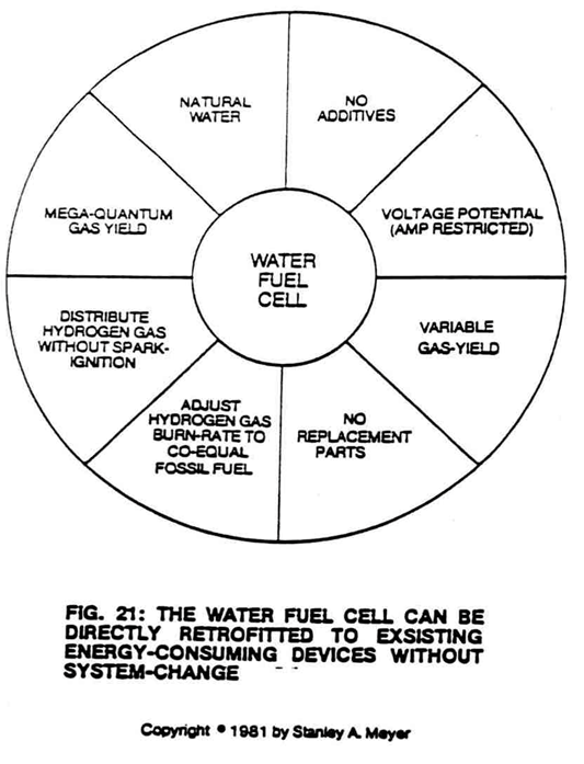 |
Fuel Cell Economics |
| 31 Utilizing Standard Gas Line to Transport Hydrogen Gas Safer than Natural Gas | 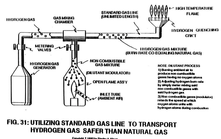 |
Spin Off Technology |
| 32 Utilizing Voltage Potential to Produce Superheated Steam on Demand | 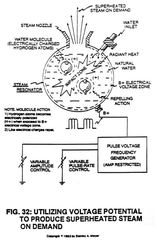 |
A Preview of Water Fuel Cell Technology and This Book; also Spin Off Technology |
| 33 Ultra High Unipolar Pulse Voltage Frequency Generator (Non-Mechanical) | 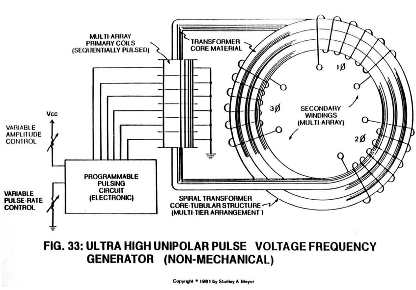 |
Dynamic Ways To Produce Electricity; also MAGNETIC SPIN GENERATOR |
| 34 Rotary Pulse Voltage Frequency Generator | 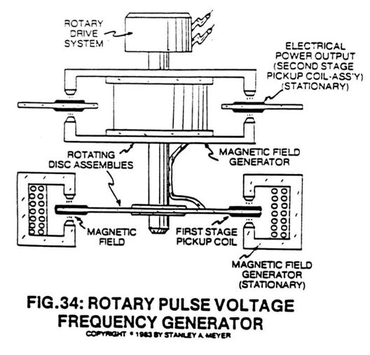 |
Spin Off Technology; also Operational Parameters of the Invention |
| 35 Solar Electrical Power Generation System | 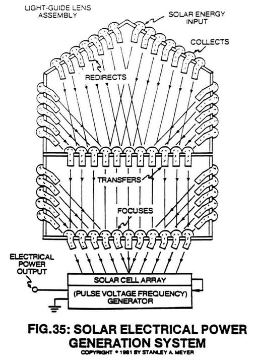 |
A Preview of Water Fuel Cell Technology and This Book; also Spin Off Technology |
| 36 Gas Driven Electrical Generator | 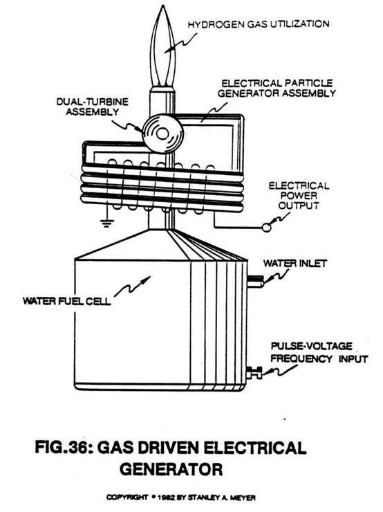 |
Dynamic Ways To Produce Electricity; also Spin Off Technology |
| 38 Thermal Pump Electrical Generator | 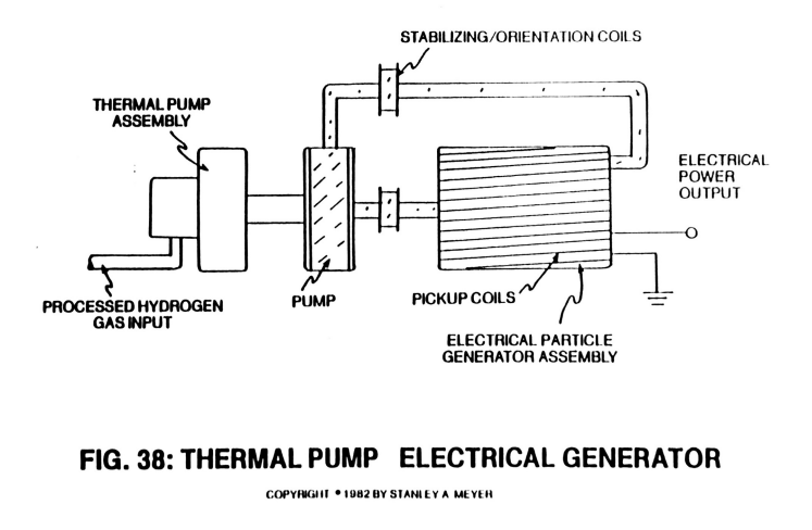 |
Dynamic Ways To Produce Electricity; also Spin Off Technology |
| 39 Hydrogen Gas Reclaim System (Water Purification) | 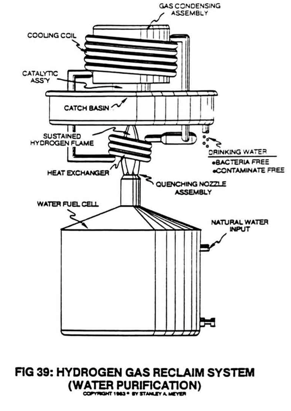 |
Catalytic Block Assembly; also Hydrogen Gas Utilization, Spin Off Technology |
| 40 Electrical Polarization Generator | 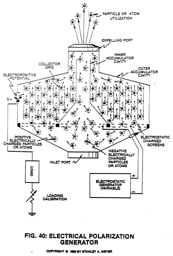 |
Mega Watt Gas Yield; also Spin Off Technology, ELECTRICAL POLARIZATION GENERATOR |
| E4A Photo: Longitudinal Resonant-Cavity Test Unit | 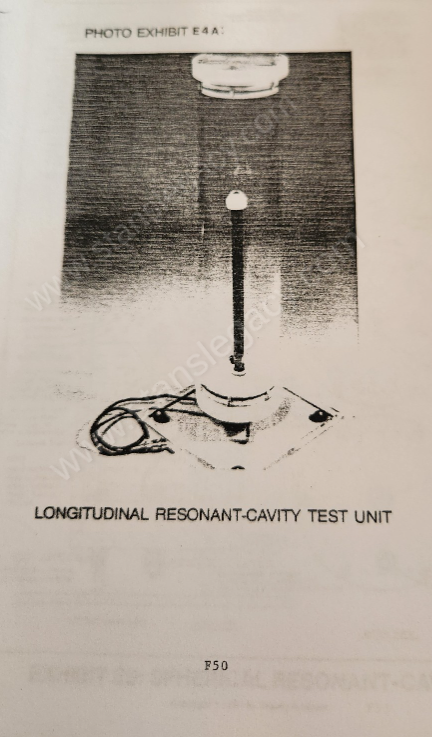 |
Exhibit E 4 A |
| E5A Photo: Spherical Resonant-Cavity Test Unit | 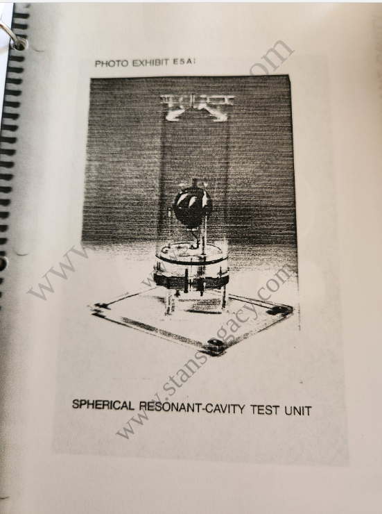 |
Exhibit E 5 A |
| E6 Photo: Laser Injected Resonant Cavity | 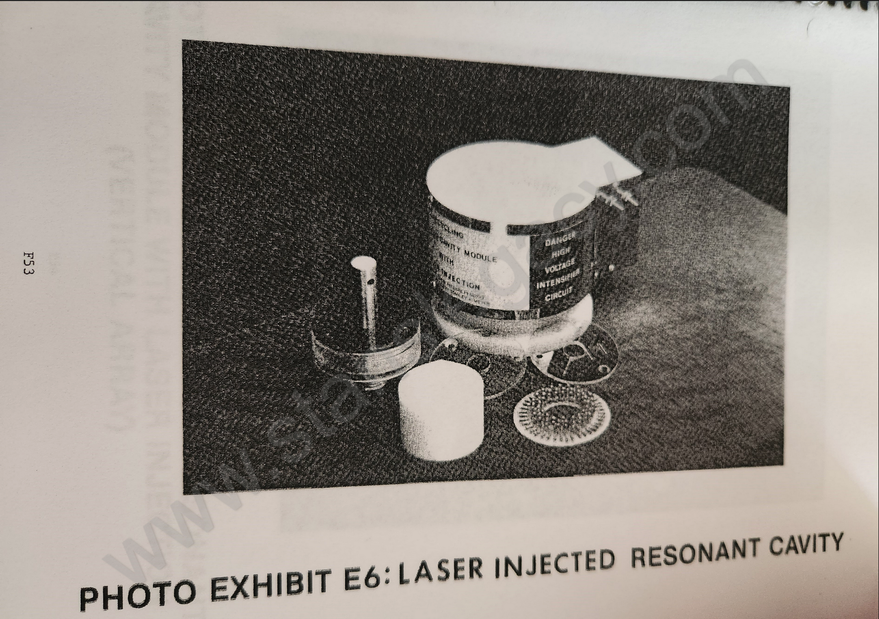 |
Exhibit E 6 |
| E7 Recycling Resonant Cavity Module with Laser Injection (Vertical Array) | 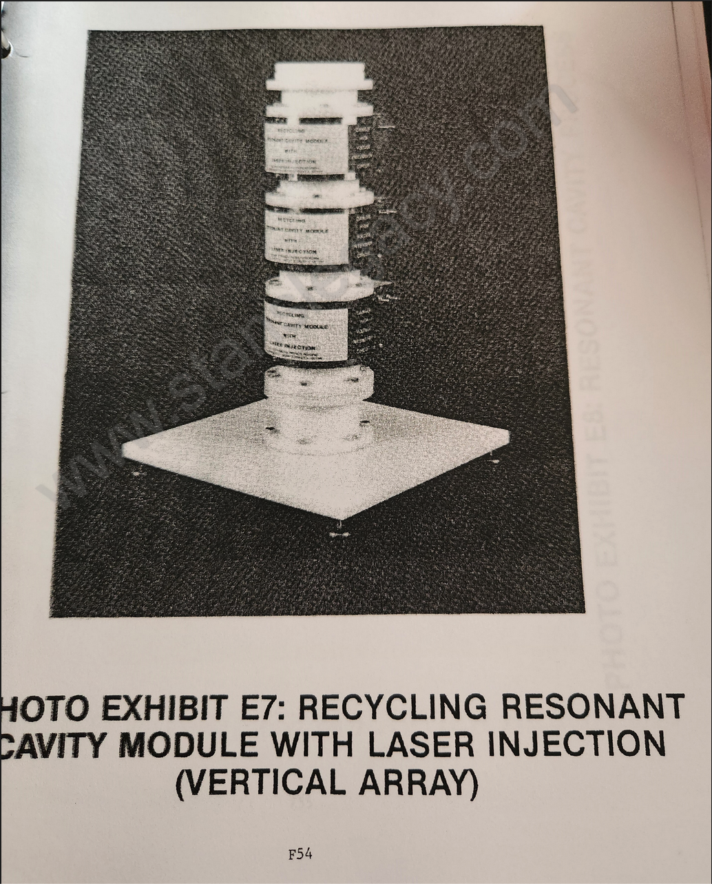 |
Exhibit E 7 |
Provenance
- Shelf
- Stan Meyer Publications
- File
- database/content/pages/dealership-manual-figures-by-number.json
- Rights
- The index was posted on 5 April 2014 as a work in progress, with GNPTrust's permission, and is reproduced for reference with its spelling corrected. The drawings are Stanley A. Meyer's; the matching is the archive's.