

article
Pulse-pattern electronics after Stanley Meyer: the analogue section (A. Mikas, August 2000)
18 August 2000
One sheet of a three-page set, hand-lettered in German: Pulsmuster-Elektronik (für H₂O-Elektrolyse) nach Stanley Meyer, pulse-pattern electronics for water electrolysis after Stanley Meyer. This is the analogue section, Analogteil (1 von 3). It is signed A. Mikas and dated 18.8.00 in its top corner, the German order of day, month and year: 18 August 2000. Nothing else in the archive, or on the open web, carries the name or the sheet.
It is a builder's page, not Stan's: a German replicator, two years after Meyer's death, designing the electronics to make the waveform Meyer described. The other two sheets, the digital section and whatever followed it, are not held.
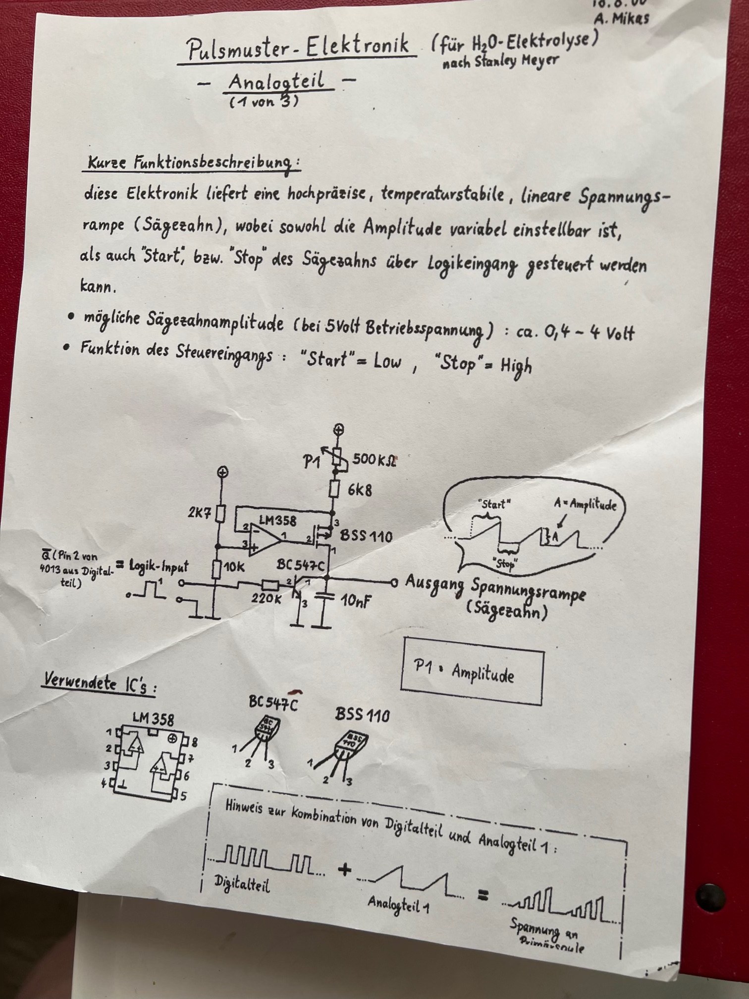
The text, and a translation
| German, as written | English |
|---|---|
| Pulsmuster-Elektronik (für H₂O-Elektrolyse) nach Stanley Meyer | Pulse-pattern electronics (for H₂O electrolysis) after Stanley Meyer |
| – Analogteil – (1 von 3) | – Analogue section – (1 of 3) |
| Kurze Funktionsbeschreibung: | Brief description of operation: |
| diese Elektronik liefert eine hochpräzise, temperaturstabile, lineare Spannungsrampe (Sägezahn), wobei sowohl die Amplitude variabel einstellbar ist, als auch „Start“ bzw. „Stop“ des Sägezahns über Logikeingang gesteuert werden kann. | This circuit delivers a high-precision, temperature-stable, linear voltage ramp (sawtooth). Its amplitude can be set at will, and the sawtooth can be started and stopped from a logic input. |
| mögliche Sägezahnamplitude (bei 5 Volt Betriebsspannung): ca. 0,4 – 4 Volt | Possible sawtooth amplitude (on a 5 volt supply): about 0.4 to 4 volts |
| Funktion des Steuereingangs: „Start“ = Low, „Stop“ = High | Control input: "Start" = low, "Stop" = high |
| Q̄ (Pin 2 von 4013 aus Digitalteil) = Logik-Input | Q̄ (pin 2 of the 4013 in the digital section) = logic input |
| Ausgang Spannungsrampe (Sägezahn) | Output: voltage ramp (sawtooth) |
| P1 = Amplitude | P1 = amplitude |
| A = Amplitude | A = amplitude |
| Verwendete IC's: LM358, BC547C, BSS110 | Components used: LM358, BC547C, BSS110 |
| Hinweis zur Kombination von Digitalteil und Analogteil 1: Digitalteil + Analogteil 1 = Spannung an Primärspule | Note on combining the digital section and analogue section 1: digital section + analogue section 1 = voltage at the primary coil |
What the circuit does
It is a constant-current ramp generator, and a careful one.
- The reference. A divider of 2k7 over 10k from the 5 volt supply puts 3.94 volts on the op-amp's non-inverting input (pin 3).
- The current source. The LM358 drives the gate of the BSS110, a P-channel MOSFET, so that the voltage at the top of the 10 nF capacitor's charging resistors, P1 plus 6k8, matches that reference. That holds 1.06 volts across them whatever the capacitor is doing, so the current into the capacitor is constant: 156 microamps with P1 turned to zero, 2.1 microamps with it at 500 kΩ. A constant current into a capacitor gives a straight-line rise, which is the linear in the description, and holding it with an op-amp rather than a resistor is the temperature-stable.
- The slope. Into 10 nF that is between 15.6 volts and 0.21 volts per millisecond. P1 sets how steep the ramp is, so for a fixed start-to-stop time it sets how high the ramp gets, which is why the box says P1 = Amplitude.
- The ceiling. The sheet gives about 4 volts as the most the ramp can reach. That is where the current source runs out of room: 5 volts less the 1.06 held across the resistors is 3.94.
- Start and stop. The BC547C sits across the capacitor, driven through 220k from Q̄ of a 4013 flip-flop in the digital section. With the input low the transistor is off and the ramp climbs ("Start"); with it high the transistor shorts the capacitor and the ramp falls back to zero and waits ("Stop").
Why a ramp
The note at the foot says what it is for. The digital section makes bursts of pulses; this section makes the ramp; added together they give Spannung an Primärspule, the voltage at the primary coil: pulse bursts whose height climbs, burst by burst, and then resets. That is close to the gated pulse train Meyer drew for the primary of the Voltage Intensifier Circuit, pulses switched on and off in groups rather than a plain square wave, with an amplitude that climbs added on top. The sheet does not say what the amplitude ramp is meant to do to the cell; it builds the shape.
What is open
Who A. Mikas was, where the set was drawn, and the two sheets that complete it: the digital section with its 4013, and the third. The archive would like to hear from anyone who has them.
Provenance
- Shelf
- Stan Meyer Publications
- Chapter
- German Edition
- File
- database/content/pages/mikas-2000-pulse-pattern-electronics.json
- Rights
- Page 1 of a three-page hand-drawn document signed A. Mikas, photographed by the archive's editor on 12 October 2026 from a paper copy kept in a binder. Reproduced for research; the drawing is A. Mikas's, the transcription, translation and notes are the archive's. Pages 2 and 3 are not held. If you are A. Mikas, or know him, the archive would like to hear from you, and to credit or remove this as you prefer.