

patent · US2574153A
Combination baking and broiling gas burner
6 November 1951
Text
Drawings
Page 1drawing sheetscan →
Page 2drawing sheetscan →
Page 3scan →
Patented Nov. 6, 1951 2,574,153 UNITED STATES PATENT of FICE
Richard H. Meiners, Milwaukee, Wis., assignor to.
A. J. Lindemann & Hoverson Company, Mill waukee, Wis., a corporation of Wisconsin
Application April 5, 1945, Serial No. 586,709.
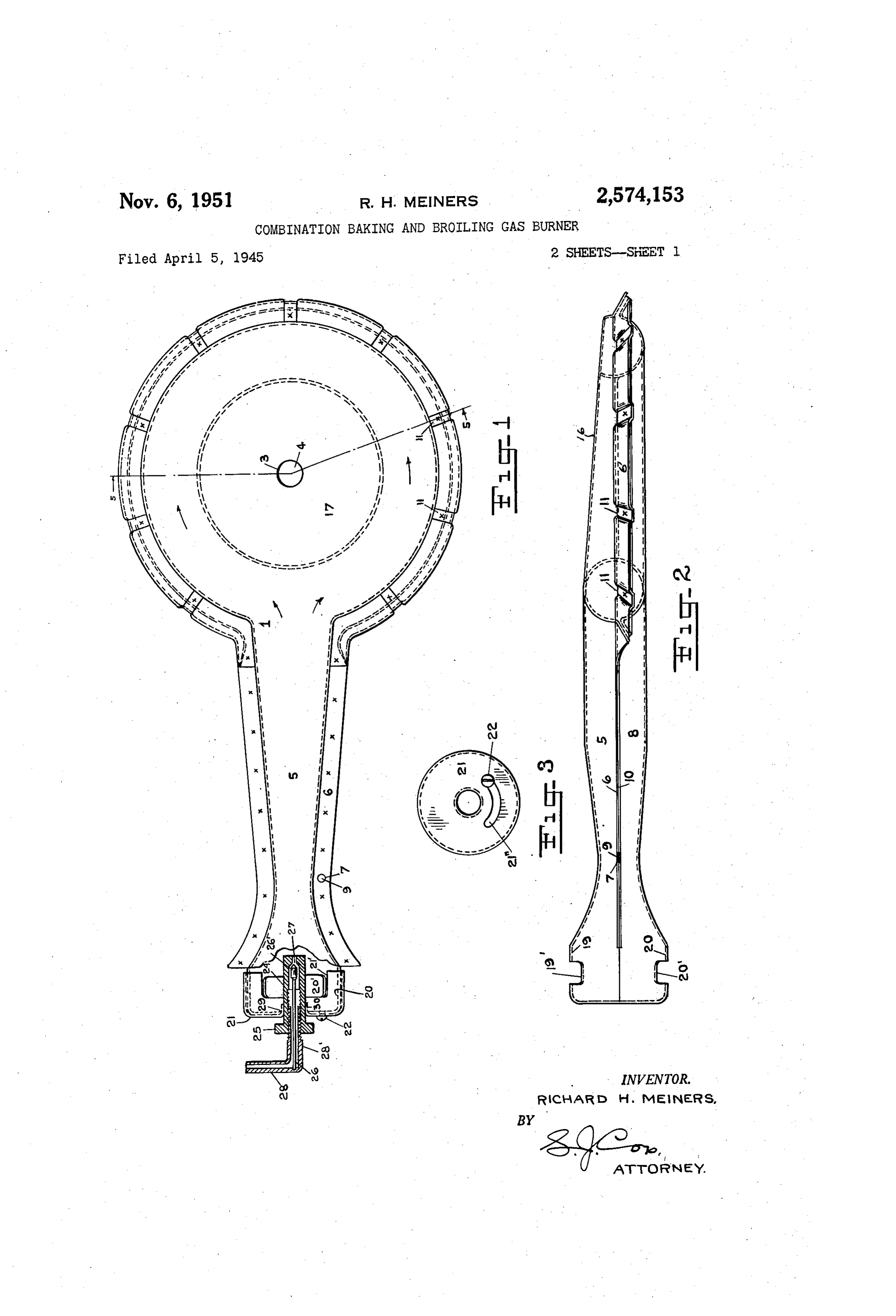
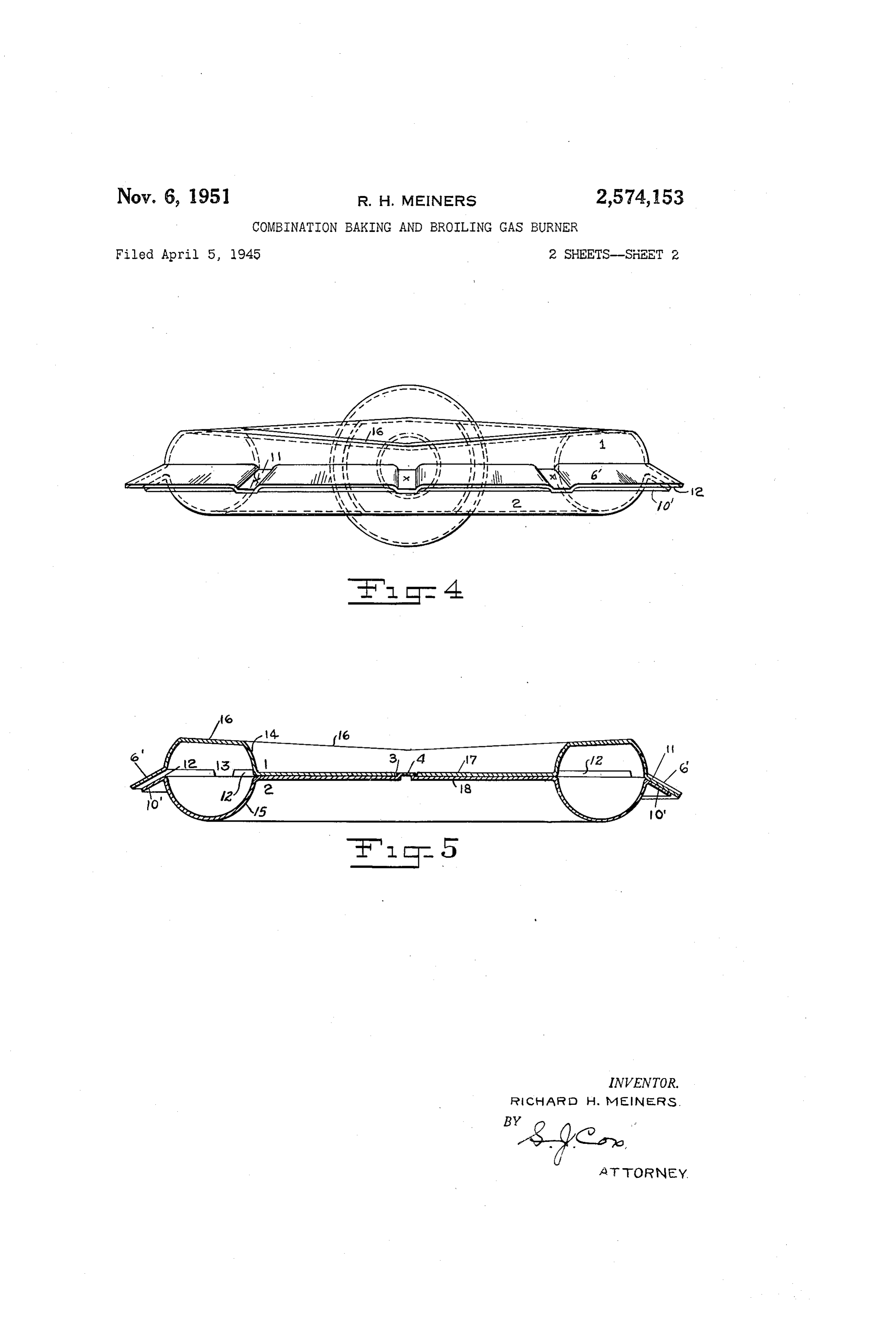
The improvements relate to gas burners and these rest on the peripheral flange 0 of the primarily to burners for use in cooking ovens lower member leaving spaces 2 between the two adapted to be employed for baking, broiling, flanges, forming slots which provide the com roasting and other cooking operations. They are, bustion Supporting ports of the burner in com however, usable in other burners. munication with the fuel distributing channel 3 Among the objects of the improvements are to between the annular bulged portions 4 and 5 produce a light, strong and simple burner of the of upper and lower members respectively. character indicated; to educe the manufactur they After the two members are placed together ing cost of the same in material, labor, manu are united by spot welding through the facturing operations and overhead; to economize 0 bottoms of the depressions fi and the flange fo and the longitudinal flanges 6 and fo, as indi the consumption of fuel thereby and increase its cated at ac, and the fabrication of the burner is heat producing efficiency, and to adapt it for use either as a single baking and broiling burner, complete.
The length and width of the slots 2 have a located in the lower part of the oven, or as two 15 definite duplicate burners mounted in the upper and relation to the width and spacing of the lower oven the upper to be employed for broiling depressions fi since it is very desirable that a and similar operations and the lower for baking, substantially unbroken ring of combustion shall roasting, etc., the burner being so constructed be maintained around the burner for satisfactory that it will serve both purposes. results, and it has been found that the slots . Other objects and advantages will be apparent 20 should be more than double the width of the to those skilled in the art from the following depressions and should be about is inch in width. description and the accompanying drawings But the interruptions in the slot ports formed by Which illustrate an exemplary embodiment of the depressions should be not more than % inch in improvements, and in which: order to have the jets of combustion overlap them Fig. 1 is a plan of the burner with the upper 25 and merge to form a continuous ring of flame at half or full fuel valve' opening. Slots 1% inches half broken away at the front end of the venturi to expose the fuel supply and mixing valve con in length and 4 inch interruption have been Struction shown in horizontal medial section; found satisfactory. The width of the slots can Fig. 2 is a longitudinal side elevation of the be accurately gauged by fixing the portions of burner; 30 the dies by which the depressions f are formed Fig. 3 is an end view of the fuel supply conduit to produce the desired spacing between the upper and the mixing valve cap; and lower members at the slots and this width Fig. 4 is an end elevation of the burner proper; can be varied with only slight changes in the and dies, as for use with natural or refined oil well Fig. 5 is a vertical section of the same substan 35 casing or other gas, at will. It has been found tially on the line 5-5 of Fig. 1. also that with this burner construction the pres The entire burner construction, including Wen sure variations in the gas mains are well taken turi and Bunsen mixing valve chamber is formed care of. As most oven burners are under thermo of two Substantailly duplicate halves except for static control it is important that the burners the positioning means and the connecting parts 40 shall be fully responsive to normal as well as between the combustion jet supporting ports and abnormal variations in pressure. these two halves are made of sheet metal stamped The fuel distributing channel 3 is fiattenied by Suitable dies into the desired form and size, so at its top and gradually reduced in area toward that they can be fitted together and secured to the portion farthest from the Venturi inlet as form the complete burner accurate in every detail 45 indicated at 6, so as to prevent the loss of pres Without measurement, finishing Work or any tools sure at that part by the venting of the gas be or appliances, and when So assembled will con tween it and the Venturi tube and a consequent Stitute a relatively light, strong and highly effi uneven flame or a failure of the flame then under Cient article. low gas supply. By providing this reduction at the top of the charinel and above the orifices 2
Referring to the said drawings, f is the upper 50 the member or half and 2 the lower member. The gaseous fuel is directed toward these ports upper member has an aperture 3 located centrally and an even supply of fuel throughout the cir of the burner proper and the lower a boss 4 fitting cumference of the burner head is insured. the same while the longitudinal horizontal flange It will be noted that the flange: 67 of the up 6 of the venturi or mixed fuel supply conduit 55 per member at the ports 2 extends beyond the section 5 of the upper has a like aperture 7 and outer edge of the flange 0 and that the two the similar section 8 of the lower has a boss 9 flanges are downwardly inclined. This not only on its flange to fitting the same. This arrange provides a groove in which the fuel. will be held, ment permits the two members to be brought for quick lighting and for even combustion at together and accurately positioned for welding 60 low valve pressure all around-the burner but together and forming the finished burner. shields the combustion against up and down The upper member around its peripheral flange drafts by deflecting the air away from the ori 6 at the burner proper has a series of depressions fices. It also directs the jets of the flame down with flat bottoms if spaced about 36° apart and wardly and spreads it laterally and downwardly 4 to some extent, So that when the burner is used warping and give added strength to the struc for broiling it will project the flame properly ture. Other variations in details of construction and when it is used for baking it will be retarded may be made without departing from the inven to a certain extent and diffused before passing to tion. The term "loop-shaped' in the appended the oven above. In this manner the burner is claims is not limited to a round or rounded loop. adapted to be used both as a broiling and a bak The combination of the closed interior of the ing burner and will dispense with the use of an burner head and the peculiar formation of the upper broiling burner. It is therefore in effect flange forming the combustion Supporting Ori a two-purpose burner. The central portion , fices produces an important result, in addition to 8 of the burner head is closed and consists of ..) insuring absolute accuracy in these parts, due a flat plate or diaphragm composed of the two to the fact that all unheated air passing upward central plates of the complemental members, Sur from below the burner must pass around these rounded by the annular fuel distributing conduit orifices, through the combustion issuing there 3 and preventing the passage of air or combus from laterally and downwardly and become min tion products through the interior. The aperture 5 gled with the highly heated productS of COm 3 in the disk portion 7 and the boss 4 in the disk bustion. The downward inclination of the upper portion 8 are located in the exact center of their portion of the fuel distributing channel is also of respective members, and fit together Snugly, SO importance and has been found to have a pe that the outer edges of the flanges 6' and O' culiar effect in Connection with the form and lo as well as the other parts in radial relation there 20 cation of the orifices and the specific gravity of to are accurately positioned. the fuel. There are also other peculiar functions When the burner is used as a top burner for and advantages of the construction and arrange frying, boiling and other purposes, the flanges ment shown and which the elements specified in forming the combustion Supporting slots may be the claims cooperate to produce, disposed horizontally or turned upwardly to a cer 25 What I claim is:
tain degree, and other orifices for the distribut 1. A combined baking and broiling oven gas ing channel may be provided. The structure burner comprising two substantially horizontal and methods and materials used in producing it, and coextensive Sections Secured together face to however, will be the same. face and made of stamped sheet metal having The mixing chamber is formed by the duplicate 30 opposed complemental upper and lower recesses recesses 9 and 20 of the members and 2 pro forming between them an air and gaseous fuel vided with air admission slots 9' and 20' respec admission and mixing chamber, a Wenturi tube tively controlled by a rotatable cap 2 fitted on extending therefrom and in communication the exterior of the chamber thus formed and thereWith at one end and a loop-shaped mixed provided with recesses 2 adapted to register 35 fuel Supply and distributing channel in com with Said slots or partly close the same according munication. With the opposite end of said tube, to the position to which the cap 2 is rotated. Said channel being tapered from proximity to This cap 2 is Secured over the end of the cham Said tube to its portion farthest removed there ber by a Set Screw 22 passed through the curved from by an inclined flattened top of the upper slot 2 f' of the cap and threaded into the end channel forming recess to equalize pressure in of the portion 20. The portions of the cap Said channel, peripheral downwardly inclined around opening 29 in the chamber are turned flanges on Said Sections surrounding said channel inwardly as shown at 30 to form a ring in which forming recesses, at least one of the sections hav the tubular valve seat member 24 is fitted. ing Spaced downward projecting portions in its The controlled inlet for gas fuel comprises this Said flange around its channel forming recess tubular valve seat member 24 having a rotating and between Said recess and the flange periphery, nut 25 on its outer end, the valve plug member the latter being substantially parallel with said 26 extending therethrough and normally into recess, the Said flange of the other section being proximity to the valve Seat 27 and the gas sup in contact with said projections whereby points ply tube 28 on the exterior of which the tubular of securement and fuel port slots between them part 24 is threaded. The valve plug member is are formed, and the upper of said flanges extend fixed in the gas Supply tube 28 and extends cen ing well beyond the periphery of said lower flange trally through its portion 28, on which part 24 and overhanging the orifices of said slots where is threaded, having at its inner end a conical by the Said slots are protected against up and plug. 26', which by being made to approach or 55 down drafts and the fuel issuing therefrom is recede from the seat 27 will regulate the amount given an OutWard and downward direction when of gas admitted to the mixing chamber surround under relatively high pressure and under lower ing it and extending into the venturi 5. pressure is distributed laterally to fill the space The Spot Weldings indicated at ac along the around the burner evenly under all pressures. flanges 6, 0, 6' and O', and located in the de 80 2. A combined baking and broiling oven gas pressions of 6', may be varied in number as burner comprising two substantially horizontal may be required or found advisable to secure a and coextensive sections secured together face tight joint between the two sections, and line to face and made of stamped sheet metal having welding may be employed to unite the flanges 6 Opposed complemental upper and lower recesses and 0. These latter flanges terminate at the 65 forming between them an air and gaseous fuel chamber portion 9, 20, so that the said portion admission and mixing chamber, a Venturi tube presents a Smooth exterior on which the cap 2 extending therefrom and in communication is Snugly fitted. The central aperture 3 and boss therewith at one end and a loop-shaped mixed 4 of the burner head in cooperation with the fuel supply and distributing channel in com aperture 7 and boss 9 of the flanges 6 and O 70 munication with the opposite end of said tube, have been found Sufficient to position the two peripheral flanges on said members surrounding Sections accurately, but additional connections Said channel forming recesses, at least one of the of this or other character may be employed. Sections having spaced projecting portions in its The disks 7 and 8 may also be welded together Said flange around its channel forming recess to insure tight contact between them, prevent 75 and between Said recess and its periphery the 5 latter being substantially parallel with said re gether and made of stamped sheet metal having cess, the said flange of the other Section being opposed complemental recesses forming between in contact with said projections whereby points them a Venturitube and a loop-shaped mixed fuel of securement and fuel port slots between then supply and distributing channel in communica are formed, and the upper of said flanges extend tion. With the inner end of Said tube, peripheral ing downwardly and well beyond the periphery laterally extending flanges on said Sections Sur of said lower flange and overhanging the Orifices rounding said channel forming recesses, Spaced of said slots whereby the Said slots are protected circumferential projecting portions on at least against up and down drafts and the fuel issuing one of the said flanges between Said receSS and therefron is given an outward and downward O its periphery, the said flange of the other being direction when under relatively high pressure and in contact with said projctions and Welded there under lower pressure is distributed laterally to to, whereby separated fuel port slots between the fill the space around the burner evenly under all flanges are formed, and one of Said flanges ex pressures, the said spaced downward projections tending downwardly and well beyond the pe being of relatively narrow width. With respect to 5 riphery of the other flange and the orifices of Said the length of the slots and Welded to the COn slots whereby the said slots are protected against tacting flange portion. up and down draftS and the fuel issuing there 3. A combined baking and broiling oven gas from is given an outward and oblique direction, burner comprising two substantially horizOntal and coextensive sections Secured together face 20 width with projections the Spaced being of Irelatively narrow respect to the circumferential length to face and made of Stamped sheet metal having Of the SOtS each Of Which extends from One pro opposed complemental upper and lower receSSes jection to the next and has its vertical width forming between them an air and gaseous fuel fixed by the vertical extent of Said projections. admission and mixing chamber, a Wenturi tube 6. An oven gas burner comprising two sub extending therefrom and in communication Stantially horizontal and coextensive Sections therewith at one end and a loop-shaped mixed Secured together face to face and made of fuel supply and distributing channel in Com Stamped sheet metal having opposed comple munication. With the opposite end of said tube, mental upper and lower recesses therein form peripheral flanges on said sections extending from the Venturi forming recesses in contact and 3. ing betWeen then, a mixed fuel Supply conduit in welded together and other peripheral flanges Sur communication with a Source of fuel gas and rounding said channel forming recesses, at least air at one of its ends, a continuous mixed fuel one of the Sections having Spaced projecting por distributing channel in connunication. With the tions in its Said flange around its channel form opposite end of Said tube and Surrounding a rigid ing recess and between said receSS and its periph 35 central portion, flat radially contacting parts of ery the latter being Substantially parallel with Said Sections comprising Said central portion, said receSS, the Said flange of the other recess peripheral flanges on Said memberS Surrounding being in contact With Said projections, Whereby Said channel forming receSSes each in contact points of Securement and fuel port slots between with the opposite flange and Secured thereto, One the members are formed, the upper of said flanges 40 of Said fianges being Spaced from the other at extending down Wardly and well beyond the intervals and united with the other at interven periphery of Said lower fiange and overhanging ing intervals around its channel forming receSS, the Orifices of Said slots Whereby the said slots whereby fuel ports slots between it and tile are protected against up and down drafts and opposite flange at least partly guaged and Secured the fuel issuing therefrom is given a lateral direc 45 by said flat partS are formed and air rising from tion, all of said members being formed by the beneath the burner is directed over the Orifices Said tWO Sections and the parts forming them of Said portS.
being integral With their respective sections. RICHARD. H. MIENERS. 4. An oven gas burner comprising two sub
Stantially horizontal and coextensive sections REFERENCES CEO Secured together face to face and made of 50 The following references are of record in the Stamped sheet metal having opposed comple file of this patent:
mental upper and lower receSSes forming between UNITED STATES PATENTS then an air and gaseous fuel admission and mix ing chamber, Wenturi tube extending therefrom 55 Number Name Date and in Communication thereWith at One end and 377,547 Daniels-------------- Feb. 7, 1888 a loop-shaped mixed fuel Supply and distributing 562,410 Moon -------------- June 23, 1896 channel in communication. With the opposite end 623,518 Crook -------------- Apr. 25, 1899 of Said tube, peripheral flanges On Said Sections 969,021 Wulfeck ----------- Aug. 30, 1910 on both sides of Said Wenturi tube and Surround 1486,668 Kielberg ---------- Mar. 11, 1924 ing Sald channel forming recesses in contact each 60 1488,677 . Hoffman ------------ Apr. i., 1924 With the flange opposite and Welded thereto one 1602,206 POSSons ------------ Oct. 5, 1926 of Said Ianges beling Spaced from the other at 1837,549 HerWig ------------ Dec. 22, 1931 intervaLS around litS Cnannel forming receSS, 2,074,531 Becvar ------------- Var. 23, 193 wereoy Iue port Siots between it and the op 65 2,348,011 Koppel ------------- May 2, 1944. posite lange are formed, each of Said members 2,372,953 Hurlbut, et al.-------- Apr. 3, 1945 peling an Integral piece of Sheet metal and each 2,386,978 Ruhl -------------- Oct. 16, 1945 having a disK Surrounded by Sald loop-shaped 2,396,800 Mills --------------- Mar. 19, 1946 (naire in radial contact With the disk of the 2,454,229 Sparrow ----------- Nov. 16, 1948 other, a centrali projection. On one disk and an 70 at vure prov 11eu lia the other of a SIZe to re FOREIGN PATENTS telive a Liu engage Said projection, Whereby the Number Country Date SecClo is are puSltioned and aligned. 8,625 Great Britain ----------- of 1886 5. A gas purner comprising two Substantially 210,301 Great Britain ------ Jan. 31, 1924 horizontal and coextensive Sections Secured to 75 487,445 Great Britain ------ June 21, 1938
Provenance
- Collection
- Patents citing this work
- Pages
- 5
- Method
- pdftotext (the PDF's own text layer) + pdftoppm 300dpi page scans
- Patent office record
- patents.google.com →
- Source
- Google Patents citing-documents table
- Assignee
- Lindemann A J & Hoverson Co
- Published
- 1951-11-06
- Transcribed from
- patentimages.storage.googleapis.com →