

patent · US2680429A
Vertical indirect water heater
8 June 1954
Text
Drawings
Page 1drawing sheetscan →
Page 2drawing sheetscan →
Page 3scan →
- Patented June 8, 1954
United states2,680,429patent office
Vertical, indirect watter heater
Ove M. Olsen, Evanston, III., assignor to Sellers
Engineering Company, Chicago, III., a corpo ration of Illinois
Application June 23, 1950, Serial No. 169,796
My invention relates to an improvement in 2
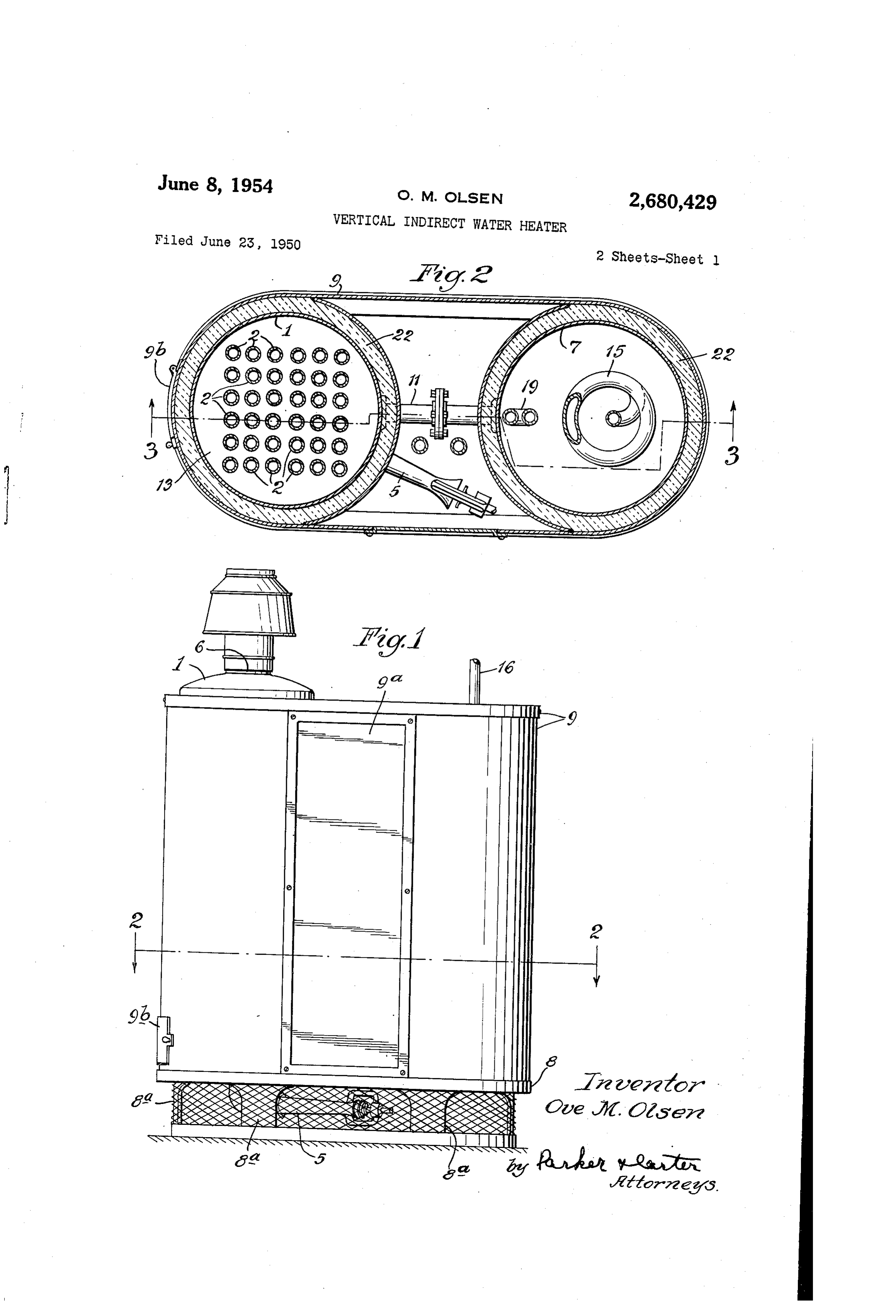
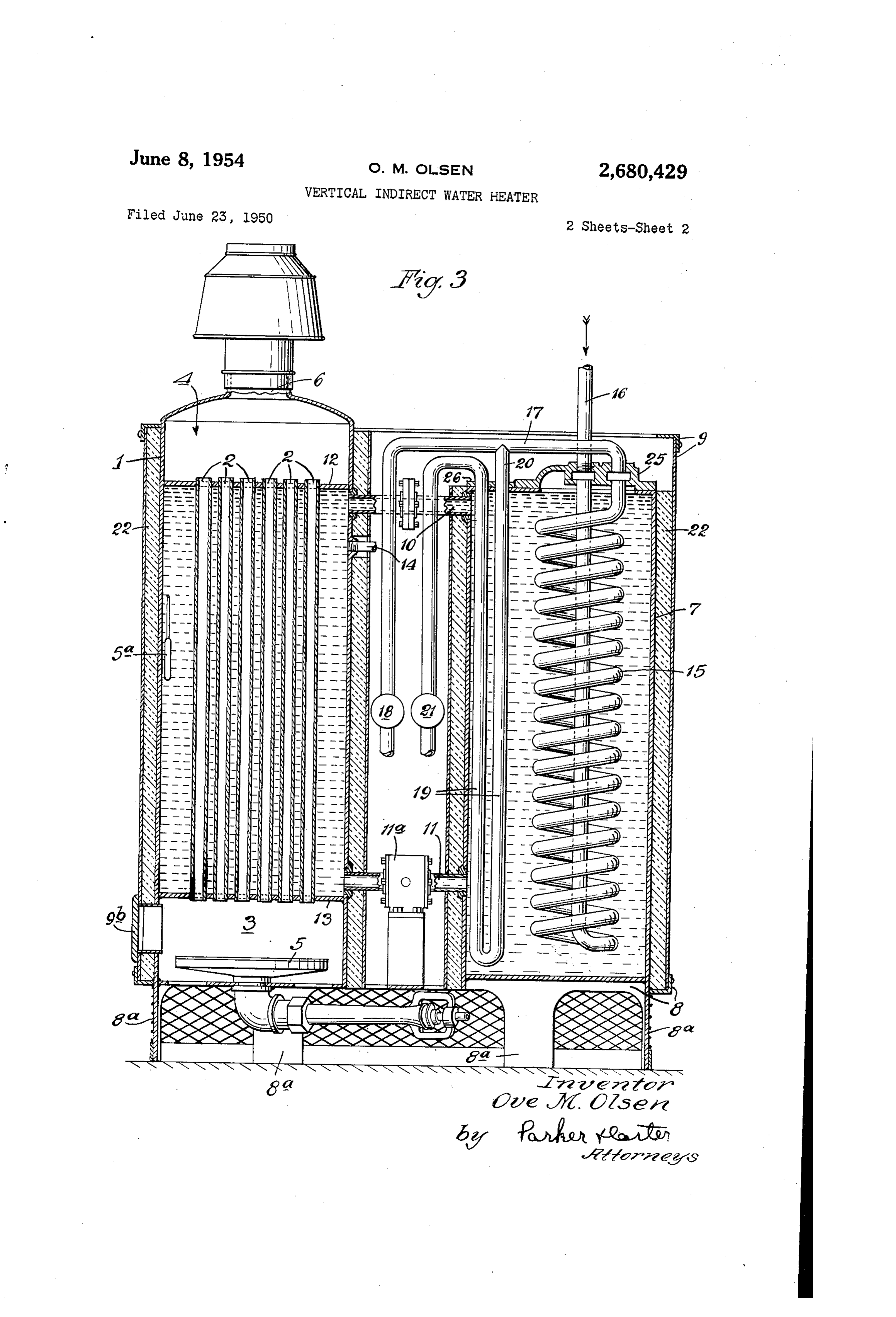
Water heaters, and has for One purpose to pro and any Suitable fuel. Under some circumstances, vide a heater adapted to heat water in large an electric heater may be provided, but I find volume, for general commercial and industrial a gas burner practical. The ducts or firing tubes US8. 2 carry the hot gases to the upper space 4, from 5 which they are exhausted through any suitable
Another purpose is to provide Such a heater in which water is indirectly heated, for example flue or Outlet 6 at the top of the heater. by means of a copper tube heat exchanger lo Located adjacent the main burner or tank f is cated in an auxiliary tank, with the water being a storage tank or element T. Iillustrate the units. heated in contact Only With the copper and not O and as of substantially the same size and drawn directly from the heater proper. vertical extension, arranged with parallel up Another purpose is to provide a heating ap right axes on a common base 8, on spaced ground paratus and method to permit the heating of cor or floor engaging Supports 8d. The tanks are rosive waters without rapid corrosion and de ShOWn as connected or surrounded by any suit struction of the heater. able housing element 9. 9a indicates an access Another purpose is to provide such a heater accesstodoor door the space between the tanks, and 9b an for the burner space 3. It will be in which water softened by Zeolite or other forms understood, that the details and proportions of of Water Softeners can be heated Without active corrosion or destruction of the heater. the above-described elements may be widely Another purpose is to provide a heater adapted 2) varied.
to deliver water in substantial quantities at at The space within the tank or heater , which east two different temperatures. - surrounds the firing tubes 2, is connected at top Another purpose is to provide an improved heat and bottom with the interior of the storage tank exchanger assembly in combination with a Water 7. I illustrate, for example, a top duct or pipe heater. 0 and a bottom duct or pipe f, which are lo Another purpose is to provide a heating ap 2 cated adjacent the horizontal top partition 2 paratus and method in which a “fly wheel effect' and the horizontal bottom partition 3, respec is employed through the use of heat exchangers tively. The space between the partitions 2 and of materials the heat-absorbing capacity of which f3, and Surrounding the fire tubes 2, is thus put is substantially greater than would be required in communication with the space within the to absorb the heat provided by the burner used storage tank, both spaces being normally filled With the heater. With a Suitable heat storage liquid, such as Other purposes will appear from time to time in Water. As will later appear, this water is not the course of the specification and claim. exhausted for use but serves as a heating and heat I illustrate the invention more or leSS diagran 3. 5 storage medium for the below described heat ex change elements within the storage tank .. 4 matically in the accompanying drawingS Where in: indicates any suitable cold water inlet for ad Figure i is a side elevation of the device; mitting Water to the interior of the boiler or Figure 2 is a section taken on the line 2-2 of heater . It will be understood, of course, that Figure 1 on an enlarged scale; and any Suitable means, passages or connections, may Figure 3 is a vertical cross section taken on 40 frombe employed for admitting or removing water the line 3-3 of Figure 2. the interior of each tank. Like parts are indicated by like Symbols It will be understood that as the liquid in the throughout the Specification and drawings. heater increases in temperature, due to the Referring to the drawings, generally indi action of whatever burner is employed, a rapid cates a hot water boiler or heater, herein shown circulation of Water is thereby set up between the as vertical, and normally filled with water. The interiors of the heater and of the storage tank water in the heater Surrounds a group or battery 7. The storage water moves rapidly upwardly in of firing tubes 2 in communication with a lower the tank f, and rapidly downwardly in tank 7, burner-receiving space 3 and an upper discharge With What approximates a piston action. This space 4, 5 diagrammatically indicates any Suit 50 Continues until the contents are at approxi mately the Same temperature. Any suitable :
able burner. For convenience, I have illustrated a gas burner the details of which form no part thermostatic means may be employed for cutting of the present invention but it will be under off the main burner 5 when the temperature of stood that any suitable burner may be employed, 55 the common body of storage water reaches a pre determined maximum. I illustrate the bulb 5a.
Page 4scan →
3 heated water available for use, I store heat, and which may be appropriately connected to the make the heat of a liquid heat storage body avail burner 5. For example, it may be set at or able to the user. An outstanding advantage of about, or between 210 degrees to 220 degrees my structure and method rests in the fact that Fahrenheit.
Located. Within the storage tank I employ 5 the Water being used does not contact the in terior of the tank for of the storage tank T. On one or more heat exchangers of any Suitable de the contrary, it flows only through the coils 5 sign and material. I prefer to employ copper, because of the superior heat-transfer capacity of and 9 which are resistant to corrosion, and which, after a proper life period, may readily be that material, but I do not wish to be limited removed and replaced by removal of the cover specifically to the employment of copper, since 10 elements or closure caps 25 and 26, respectively. other materials of high heat-transfer capacity Another highly advantageous feature of my may, under some circumstances, advantageously. System is that although the Second coil or heat be employed. exchange member 9 draws heated water which Considering the exemplification of my invent. has already been pre-heated in the coil or heat tion as shown in the drawings, I illustrate a spiral- lis" eXchange member is, it does not normally inter copper tube heat exchanger 5 having an inlet fere with - or. reduce-the heat-absorbing capacity pipe 6 and an outlet pipe 7 extending to- any of the heat exchange member 5. It is only when suitable water mixer or blender 8, the function theire is a demand for the more highly heated of which is below discussed. 9 indicates a see ond heat exchanger in the form of a U-shaped 20 water produced by the heat exchange member 9 tube; one arm of which is connected, as by the that it-draws on the coil or heat exchange mem pipe 20, with the outlet. i. of the heat exchanger ber 5. Except when there is a call for the more 5. The outlet temperature of the Water from highly heated water, a static Supply of heated: the heat exchanger, or coil 9" is controlled by Water is naintained in the heat exchange men- - means of a second water nnixer or blender 2. 25 mostatically ber 9, with no flow into it or out of it. By ther:-- The blenders may be therinostatically controlled, controlling the two bienders, and by Stich controls not of themselves forming part of Setting one blender at, for example, 140 degrees: my invention. The water boileir and storage Fahrenheit, and the other at, foi example, 1803 tank may be surrounded with any Suitable in 30 of degrees Fahrenheit, E-maintain adequate delivery: water at two temperatures.
Sulation as indicated at 22. While I do not wish to be limited specifically It will be realized that, whereas, I have de to the forms and relationships of tank shown, I Scribed and illustrated a practical and operative method and device, nevertheless many changes: find it highly advantageous to employ a vertical: heatar With a vertical Storage tank mounted ad may be made in the size, shape, number and diisi jacenÈ to it, With the interiors of the tanks con-" position of partS Without departing from the 35. nected to bring about a rapid circulation of liquid spirit of my invention. I therefore wish Iny de between the two tanks in response to heating scription and drawings to be taken as in a broad the liquid in cine of the tanks, the two tanks: sense iliustrative or diagrammatic, rather tha? being arranged, Side by side, and at about the as limiting me to lay precise showing. Foi ex samme i level. For convenience of motinting, the ample, whereas i iliustrate a multiple tank Sys- 40 tanks may be made of the same, or substantially tem, I do not wish to be so limited. the Sane, size, as well as shape. The use and operation of the invention are as With my structure easily supply water at follows: two different temperatures without, the need of: Let it be assumed as an illiaStrative example that a teaperature of from 210 degrees to 223 45 using in any booster heater. This is of advantage' restaurant instaliations, where the propor degrees Fahrenheit is maintained in the heat tions of low and high temperature water vary Storage liguid contained in the heater tank continually during the period of use. High-tem and in the storage tank . The incoming watei perature Water may be used in the rinse: sprays entering the heat exchange coils or eleients 5 of dishwashing machines. Low tenperature and 3 rapidly becomes heated by absorbing heat 5t Water inay be used for various miscellaneous from the liquid in the storage tank i. It inay be puipCSes, Such as pre-rinsing dishes before they heated to a terriperature Somewhat in excess of entei' the Washing machine, cleaning pots and the desiredi otitlet terminperattire, britut- the otitlet" temperature inay be controlled by any suitable i pains in Scullery sinks, and for general use in lavatories, etc. When the washing machines therinostatically controlled mixei's or blenders 3 are not being used, and there is no call for high and 2i, which add cold water from any suitable temperature water, the entire capacity of the connections to bring allout the desired operating main heat exchange' is available for supplying or delivery temperature. Water at the lower temperatures. It is only In the embodiment of my invention herein shown i take advantage of the heat-absorbing 60 When higher temperature water is called for that Water is drawin through the supplemental or capacity of the copper tube heat exchangers' booster coil 8. Otherwise, there is no fiow of which is several tilies gi's atter than would be re Water along the pipe or connection: 28, and the quired to absorb the heat provided by the burner entire delivery of water along the pipe I TI flows and which thus produces what I may call a, “ily through the main heat exchanger coi {5. A re Wheel' effect. The heat stored in the body of 5 quirement of dishwashing machines is that a liquid contained in the two tanks is available high rate of ficw of high temperature water is for absorption by the heat exchanger coils 5 necessary for a period of approximately ten. and 9, in addition to the heat which is cur Seconds out of every minute of operation. This rently being put into the water in the tanks by momentary, but high, output may be in a volume the burner. The user thus has available the heat 70. of from One-half to three gallons of water. The: stored in the water contained in the two tanks, capacity provided by my tenperature coil is such. and the use of copper tube heat exchangers of that all, or a large part, of the necessary volume: sufficient capacity to absorb this stored heat, as of high temperature water is stored within the well as the burner-delivered heat, increases the coil, and is thus available for instant use. Since. efficiency of the heater. Thus; instead of storing 75 5 the requirement for high temperature Water at form a closed circulating system, a heater for the high rate is for a period of approximately heating the liquid in one of the Said containers, ten seconds, with a stand-by period of approxi generally upright fue elements passing through mately fifty seconds in each cycle of Operation, the chamber in the said one container to facili the contents of the coil are brought up to the tate the heating of the liquid in that chamber, desired temperature during the stand-by period, and an elongated heat eXchange member posi and the necessary volume of high temperature tioned in the other container and extending into Water is available when the call for high tem its chamber in the path of the closed circulating perature Water Comes.
The equipment shown has the advantage of ) System exchange and having a substantial amount of heat area for contact with the liquid, the occupying a small amount of floor space, due to liquid in the closed circulating System generally its compact assembly and arrangement. I en flowing upwardly in the chamber of the said one ploy large-diameter copper tubes in the heat container and downwardly in the chamber of exchangers, which materially reduces the likeli hood of scale formation in the tubes When used 5 the said other container, the elongated heat eX change member being insertable and Withdraw on hard Water. The probability of Scale forma able through the top of the said other container, tion is further reduced, as compared with the said elongated heat exchange member having an direct fire instantaneous type of copper Water inlet adapted to be connected to a source of Water coil heater. In my unit the temperature dif Supply to be heated and an outlet connection for ferential between the water on the outside of 20 the delivery of heated water, the elongated heat the coils 5 and 9 and the Water being heated on the inside is very low, approximately 10 eXchange member extending from the top of the chamber of the said other container approxi degrees to 70 degrees Fahrenheit. In direct-fire mately to the bottom and including two heat instantaneous heaters, on the contrary, the dif eXchange elements, one of the elements includ ferential may frequently be as high as 2,000 25 ing the inlet connection adapted to be connected degrees Fahrenheit, due to the high temperature to the Source of water to be heated and the out Of the gas flame on One side of the coil and the let connection for the delivery of heated water low temperature of the water being heated on the other side of the coil wall. This high differential and the other heat exchange element having an inlet connection from the outlet connection of greatly accelerates the formation of scale inside 30 the the coils, a factor which is entirely avoided by said one heating exchange element and a my structure. Separate outlet connection for the delivery of I diagrammatically illustrate, in Figure 3, a heated water from the other heat exchange ele pump a. In most instances, it is not necessary ment, the said one heat exchange element having t0 uSe Such a pump, but, under Some circum 35 area, a substantially greater amount of heat exchange than the other.
stances, in order to accumulate a control circu lation, Such a circulating pump in the line or pipe , connecting the two tanks, is of value. It may References Cited in the file of this patent Serve the dual purpose of maintaining a substan - UNITED STATES PATENTS tially absolute uniformity of temperature 40 Number throughout the entire system, and of increasing Name Date the heat transfer rate or capacity of any given 142,534. Trowbridge -------- Sept. 2, 1873 heat eXchanger. For example, velocity of the 781,818 Fournier ---------- Feb. 7, 1905 liquid Surrounding a copper coil is an important 1,604,280 Haag -------------- Oct. 26, 1926 factor in determining the rate at which heat is 45 1,742,329 Ullman ------------ Jan. 7, 1930 transferred through the coil. 1934,496 Glisson ------------ Nov. 7, 1933 I claim: 1951,403 Goddard ---------- Mar. 20, 1934 In a Water-heating System, a heat storage unit 1,959,286 Grebe ------------ May 15, 1934 divided into two generally upright containers, 1,971,139 Harris ------------ Aug. 21, 1934 each having a chamber adapted to receive and 50 2,003,742 Elliott ------------ June 4, 1935 contain a body of liquid, the chambers being 2,047,864 Fite -------------- July 14, 1936 interconnected for liquid transfer generally 2,151,108 Hultgren --------- Mar. 21, 1939 adjacent their tops and bottoms respectively to 2,201406 Miller ------------ May 21, 1940
Provenance
- Collection
- Patents citing this work
- Pages
- 5
- Method
- pdftotext (the PDF's own text layer) + pdftoppm 300dpi page scans
- Patent office record
- patents.google.com →
- Source
- Google Patents citing-documents table
- Assignee
- Sellers Engineering Company
- Published
- 1954-06-08
- Transcribed from
- patentimages.storage.googleapis.com →