

patent · US2692483A
Refrigeration unit utilizing solar energy
26 October 1954
Text
Drawings
Page 1drawing sheetscan →
Page 2scan →
Patented Oct. 26, 1954 2,692,483
United states patent office
Refrigeration unit utilizing solar
Energy
Arthur W. Hedlund, Minneapolis, Minn.
Application January 5, 1951, Serial No. 204,665
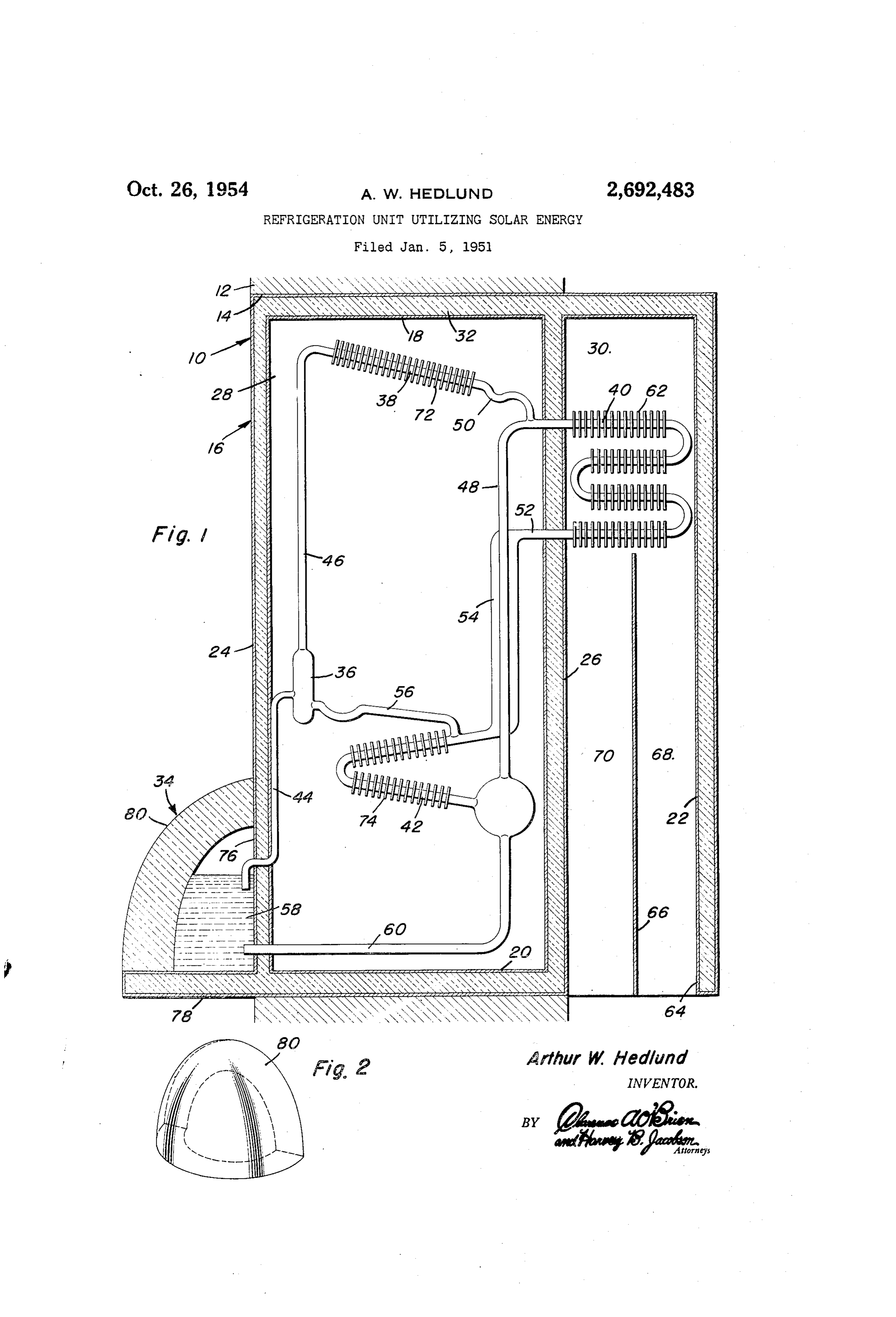
This invention pertains to new and useful im Figure 1 is a vertical transverse sectional view provements in refrigerating apparatus, and re of a Suitable embodiment of the present inven lates particularly to apparatus uniquely adapted tion; and to utilize Solar energy for the purpose of either Figure 2 is a perspective view of the Solar en refrigerating or air conditioning an enclosed 5 ergy Concentrator.
Space. Reference is now made more specifically to the The primary object of this invention is to accompanying drawing, wherein like numerals utilize Solar energy for the purpose of producing designate similar parts throughout the various a refrigerating effect, and to provide an appa views, and in which a Wall section is designated ratus which will operate with at least as great O generally at 0. It will be understood that the efficiency in hot climates as in cool climates. Wall Section 0 constitutes only a portion of a Another important object of this invention is Wall construction, not shown, built to enclose a to provide an apparatus of this character which refrigerated Space that appears to the right of Will operate at optimum efficiency throughout the the Wall Section 0 as shown in Figure 1. day, that is, an apparatus in which the relative The wall section O includes a wall 2 having angular movement of the sun during the day an opening 4 therethrough in which is positioned will not materially effect the efficiency of the a housing designated generally at 6. apparatus. The housing 6 includes top and bottom walls Yet another important object of the present in 8 and 20, respectively, and inner and outer Walls vention is to provide an apparatus of this char 22 and 24, respectively. It will be noted that the acter which Will occupy a minimum of otherwise Walls 22 and 24 are preferably parallel to the useful space, and in which the housing therefor Wall 2, and that in addition the interior of the Will constitute a part of the insulation surround housing f6 is provided With a partition 26 that is ing the Space being refrigerated thereby. also parallel to the walls 22 and 24 so as to di Still another important object of the present in 2 5 wide the interior of the housing 6 into cham vention is to provide an apparatus of this chair bers 28 and 30. In the preferred construction, acter which will afford an excellent heat ex the Walls 18, 20, 22 and 24, as well as the par change with the medium being cooled thereby. tition 26 are hollow, and are filled with a suit A meritorious feature of the present, invention able heat insulating material 32. resides in the provision of a concentrator for col 30 The present invention includes an absorption lecting and directing the solar energy striking type refrigeration System. Which includes a gen the same to the generator, which will operate at erator designated generally at 34, a separator Optimum efficiency irrespective of the declina 36, a condenser 38, an evaporator 40, and an ab tion of the Sun or the hour of the day. sorber 42. A conduit 44 communicates between Another important feature of the present in 35 the generator 34 and the separator 36, the upper vention resides in the positioning of the appa end of the latter in turn communicating with the ratus almost entirely within a wall enclosing the condenser 38 through a conduit 46. The upper refrigerated space, so as to constitute a portion end of the evaporator 40 is connected to the lower Of the insulation therefor. end of the absorber 42 by a conduit 48 and to the A final important feature of the present inven 40 discharge end of the condenser 38 by a lateral tion to be specifically enumerated herein resides conduit 50. The lower end of the evaporator 49 in the positioning of the evaporator and the communicates With the upper leg of the absorber structure Surrounding the same that is adapted to 42 through a conduit 52, it being noted that its induce air circulation to afford better heat ex intermediate portion 54 of the conduit 52 Suur change by conduction, and which construction 45 rounds a portion of the conduit 48 SO as to be in Will still avoid the creation of excessive cold drafts heat exchange relation therewith. Finally, the that would be objectionable when the device is absorption refrigeration circuit includes a con used for air conditioning in a home or office. duit 56 which communicates between the lower These, together With various ancillary objects end of the Separator 36 and the upper leg of the and features of the invention which will become 50 absorber 42.
apparent as the following description proceeds, AS Will be understood, the showing of the ab are attained by the present invention, a preferred sorption refrigeration circuit is substantially dia embodiment of which has been illustrated by grammatic, and since in itself it does not con way of example only in the accompanying draw stitute the claimed subject matter of the present ings, wherein: 55 invention, it is believed that a brief description
Page 3scan →
Of the operation of the same will suffice since the 28, the compartment 28 is vented by means, not operation of such devices is well understood by shown, through the Wall 28 to permit the escape those skilled in the art. The System is, of Course, of Such liberated heat.
of the type operating with Water, ammonia, and The generator 34 comprises a portion 76 of the hydrogen, of which only a concentrated mixture, 5 wall 24 and outwardly extending portion 8 of the or solution of ammonia in water 58 is present in bottom wall 20, and a radiant energy concentrator the generator 34. Upon the application of heat 80. The concentrator 8 in conjunction With the to the Solution 58 in the generator 34, VaporS Con wall portions 6 and 78 constitute a housing for sisting primarily of ammonia are driven upwards the fuid 58, the concentrator 8 being Substan through the conduit 44 to the separator 36, where O tially a shell that rests upon the wall portion 48 portions of the vapors which have condensed in in sealing engagement with both of the wall por the conduit is and the separator 36 drain from tions 6 and 78. As best shown in Figure 2, the the separator 36 into the upper leg of the ab concentrator 3) is concavo-convex in shape, and sorber 42 through the conduit 56, the uncondensed is substantially semi-cylindrical in horizontal Sec portions of the vapors (substantially pure am 5 tion throughout its vertical extent, and is Sub monia) passing on upwardly through the conduit stantially semi-cylindrical in vertical section 46 to the condenser 36 where they are cooled Sufi taken parallel to the wall portion 76. In addi ciently to pass into the liquid phase. The am tion, the concentrator 80 is formed of transpar monia, condensed in the condenser 38 then passes ent material, and is preferably of a material par into the upper end of the evaporator 69 through ticularly high in transparency as to heat or infra the conduit 5 to pass downwardly therethrough red radiation. Further, the shape of the con where the same meets a counter-current flow of centrator 8, and its index of refraction are pref upwardly moving hydrogen, so that by Virtue of erably such that radiant energy emitted from any the reduction of the partial pressure of the am source disposed within the dihedral angle defined monia, vapor in the evaporator 43 due to the pres by the wall portions 76 and 18 striking the same ence of the hydrogen gas in the vapor phase, the will be collected and directed to the fluid 58 within ammonia, evaporates to move upwardly with the the generator 34 so as to heat the fuid 58. It hydrogen gas and then downwardly through the will be noted that both the Wall portions 6 and conduit 48 to the lower leg of the absorber 42. 8 are insulated to prevent the escape of heat The mixture of ammonia vapor and the hydrogen 30 from the fluid 58, and in addition it is preferred gas then moves upwardly through the absorber that the material of which the concentrator 80 42 counter-current to the flow of water passing is formed be also of a material possessing low downwardly through the absorber 42 from the thermal conductivity to prevent the escape of conduit 56, so that the mixture of ammonia vapor heat through the concentrator 8 by conduction. and the hydrogen gas is stripped of the ammonia 35 The use of the present invention will be readily due to the extreme solubility of the ammonia appreciated. The housing le will be disposed in vapor, and the concentrated Water Solution of a wall 2 lying in an east-west direction with the ammonia, vapor passes downwardly from the concentrator 88 facing toward the equator, So lower end of the absorber 42 through the conduit that in temperate zones the concentrator 86 will 68 to return to the generator 34, the stripped hy 40 be exposed during the hours of daylight to the drogen gas passing upWardly through the con radiations of the sun. Of course, When the pres duit, 52 from the upper end of the absorber 42 to ent invention is to be utilized in the tropics, it the lower end of the evaporator 40. will be preferred that two of the constructions It will be noted that the entire absorption re shown in Figure 1 will preferably be employed, frigeration circuit is disposed within the con one of which faces towards the equator with the partment 28 with the exception of the generator 45 other facing away from the equator, So that 34 and the evaporator 4C, the generator 34 being throughout the seasons at least one of such units disposed outside of the wall section Fe, while the will be exposed to the Sun's radiation, evaporator i is disposed within the compart Obviously, the apparatus will be charged with ment 3). Inasmuch as it is desired that the the proper quantities of water, annonia, and evaporator 49 have good heat eXcharage with its hydrogen for optimum refrigerating perform surroundings, the evaporator 40 is provided With arice, such quantities being dependent om the a plurality of heat exchange fins 62. In order volumetric capacity of the entire apparatus and to further enhance the heat eXchange of the the relative size of the components thereof. It evaporator. 4 with its surroundings, the botton is contemplated that the charging of the ap of the compartment 38 is open as at 64, and a 2, paratus and the installation thereof may be baffle 6 is disposed within the compartinent 35 facilitated by an alternative construction of the to extend in parallel relation with the Walls 22 same, not shown, in which a Separate container and 24 in spaced relation with the wall 22 and the will be provided for the liquid contained in the partition 26 below the evaporator ). The pur pose of this arrangement is that Warm air Will 60 tainerconcentrator heat and placed therein, such con being provided with couplings for detach rise in the space 68 between the baffle 66, and the ably connecting to the conduits 44 and 60. wall 22 to pass in intimate contact with the evapo From the foregoing, the construction and op rator $9 to become cooled and descend in the eration of the device will be readily understood space is between the baffle 66 and the partition 26. 65. and further explanation is. - believed to; be un In order to facilitate the heat exchange of the necessary. However, since, numerous medificar condenser. 38 with its surroundingS SO as to con tions and changes, will readily occur to... those pensate, for the heat of vaporization of the an skilled in the art, it is not desired to, limit, the ill monia, the condenser 38 is provided with a plu-, vention to the exact construction shown, and rality of heat exchange fins 72, and in a Similar 70 described, and accordingly, all suitable modificar, manner, the absorber 42 is provided With a, plu tions, and equivalents may be resorted to, falling: rality of heat exchange fins 24 in order to con Within the scope of the appended: Glains; pensate for the heat of Solution of annonia in Having described the invention, What is, water. Since both the condenser 38 and the ab clained as new is: m sorber 42 liberate heat, within the compartment. 5. 1. A refrigerating apparatus comprising a Wall:
Page 4scan →
section having a chamber therein, an absorption sealing relation to the outer Wall of said housing, type refrigerating System including a separator, a Said Shell enclosing a refrigerating fluid, Con condenser, and an absorber disposed in said nections between Said Shell and Said CondenSer chamber, said System also including an evapora and Said absorber.
tor coil disposed on One side of the Wall Section. 5 4. For use in an absorption type refrigerator and a generator disposed on the other Side of the a solar energized generator comprising a pair of wall Section, Said generator including an eXposed angulated walls, a concavo-convex Wall sealed to transparent Wall having optical properties said pair of walls to provide an enclosed shell, all adapted to collect and direct solar energy strik of Said Walls being constructed of material hav ing the same into the interior of the generator. O ing loW termal conductivity, Said concavo-conveX 2. A refrigerating apparatus comprising a Wall wall being constituted of a material which is sub Section having a chamber therein, a partition in Stantially transparent to radiant energy having a Said chamber lying substantially parallel to the Wave length of the Order of infra-red, means for plane of the Wal Section dividing the chamber introducing a filling of refrigerant mixture into into first and second compartments, an absorp 5 said shell, an outlet conduit adjacent the top of tion-type refrigerating Systern including a Sep Said chamber.
arator, a condensei and an absorber disposed in 5. In a refrigeration apparatus of the absorpor the first compartment, said Systein also including tion-type, a vapor generator comprising a liquid an evaporator disposed in the second compart mixture container including a pair of angularly ment and a generator disposed on the outside of 20 disposed walls, said walls being constructed of a the Wall Section on the Side thereof renote from material having a low thernal conductivity, a. the Second compartment, Said Wall Section haW concavo-convex Wall sealed in liquid-tight rela ing an opening communicating through the bot tion to Said angularly disposed Walls, Said Con ton of the Second Cornpartment. With the OutSide cavo-convex Wall having an index of refraction. of the Wall Section on the Side opposite the gen Such that it is Substantally transparent to radia erator, a baffle in Said Second compartment above tion of the Order of infra-red radiation, a refrig Said opening and below the evaporator, Said gen erant mixture inlet adjacent the bottom of the erator including an exposed transparent Wall Space enclosed by Said Walls, a fluid outlet ad having Optical properties adapted to collect and jacent the top of Said Space, a refrigerating net direct radiant Solar energy Striking the Sane into 30 Work connected between Said outlet and inlet. the interior of the generator.
3. A refrigerating apparatis for installation: in References Cited in the file of this patent a Wall opening comprising a housing mounted UNITED STATES PATENTS in Said opening and extending into the Space Number Nare Date bounded by Said Wall, a partition in Said housing 35 671,810 Thurstensen. ————————— Apr. 9, 1901 providing first and second chambers, said parti 751.058 - Cracknell ----------- Feb. 2, 1904 tion being Substantially parallel to said Wall, an 2,030,350 Bremser —————------ Feb. 11, 1936 absorption-type refrigerating System, said first 2,213,894 Barry ------------- Sept. 3, 1940 chamber enclosing a condenser and an absorber 40 2,221971 FHayWOOd -------------------- Nov. 19, 1940 of Said system, said second chamber housing the 2,230,917 "4"riana -------------- Feb. 4, 194 evaporator of Said Systern, the botton of Said 2,261,682 Hedlund -——————————— Nov. 4, 1941 second chamber being open, a baffle in said sec 2,261,683 Kuenzli –––––––––––– Nov. 4, 1941 ond chamber below said evaporator, said ba?fle 2,297,761 HainSWOirth --------- Oct. 6, 1942 eXtending Substantially parallel with Said parti 2,342,062 Schenck ------------ Feb. 15, 1944 tion, a botton portion of Said housing extending 45 2,388,940 Taylor ------------- Nov. 13, 1945 OutWardly from Said, Wall, a generator including a. Shell resting On Said extending portion and in
Provenance
- Collection
- Patents citing this work
- Pages
- 4
- Method
- pdftotext (the PDF's own text layer) + pdftoppm 300dpi page scans
- Patent office record
- patents.google.com →
- Source
- Google Patents citing-documents table
- Assignee
- Arthur W Hedlund
- Published
- 1954-10-26
- Transcribed from
- patentimages.storage.googleapis.com →