

patent · US2763322A
Two-stage valve for torch devices
18 September 1956
Text
Drawings
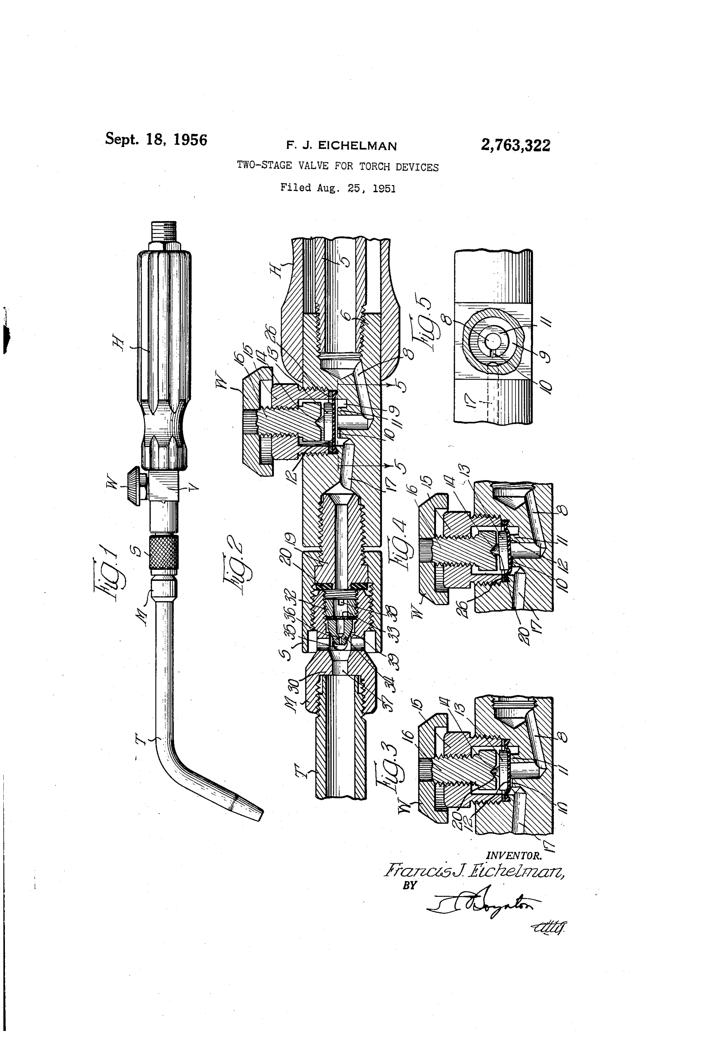
Fig. 2 is an enlarged partial longitudinal section through the valveposition;
Page 1drawing sheetscan →
Page 2scan →
United States Patent Office 2,763,322 Patented Sept. i. 8, 1956
Fig. 2 is an enlarged partial longitudinal section through the valveposition;
opened and handle of Fig. 1 showing the valve in fully 2,763,322 Figs. 3 and 4 are sectional views showing the valve of TWO-STAGE WALVE FOR TORCH, DEVICES Fig. 2 partially opened to permit a pilot flow of gas and Francis J. Eichelman, Brookfield, Ill., assignor to National in fully closed position, respectively; Cylinder Gas Company, Chicago, I., a corporation of Fig. 5 is a top view of the valve body taken along Delaware the line 5-5 of Fig. 2 and partially broken away to show the construction of the valve seat.
Application August 25, 1951, Serial No. 243,663 O My novel valve and handle assembly as shown in 3 Claims. (C. 158-27.4) Fig. 1 attached to a soldering or welding tip T includes a handle H, valve body V, valve wheel W, and an in ternally threaded sleeve S. The tip T is provided with a combination air aspirator and mixer M which is ex
My invention is an improvement in torch devices that 5 ternally threaded to engage the sleeve S. burn a combustible mixture of air and a fuel gas. More According to my invention, I have constructed the specifically it is concerned with such devices in which the torch is supplied with a fuel gas, such as acetylene it is attached to thea hollow valve V to provide two-stage or differential action, and handle H which is in axial or another hydrocarbon gas, and an appropriate quantity alignment with the valve body to provide a gas or fluid of air which is aspirated into the torch from the sur 20 passageway on both sides of the valve. The hollow rounding atmosphere to form with the fuel gas a com handle H is fitted with a small tube communicating with bustible mixture that will produce a flame of the desired the valve body and a threaded fitting which may be con characteristics. The torch devices of this invention are nected to a source of fuel gas supply by means of a useful for various purposes, for example, to provide heat flexible hose or the like.
ing flames for welding, brazing and soldering operations. 25 The valve V is of two stage or differential operation Torches used for welding, brazing or soldering are in that initially a very small gas flow is uniformly con subject to an intermittent use, and it has usually been trolled by regulating the size of the passage through a necessary in the past to reestablish the flame and adjust very small opening. This constitutes the first stage of the fuel Supply to obtain the appropriate heating flame the valve's operation.
after each operation. I have found it desirable to be 30 Subsequently, as the valve wheel W is further turned, a able to regulate the flow of fuel, establish a pilot flame diaphragm which regulates the first stage opens to regu and also completely shut off the flow of gas by means late the gas flow through a second and much larger gas of a single control and one simple two-stage unitary passage. This second stage is also uniformly regulated valve. For example, to maintain a pilot flame, the valve and is quick-opening in nature as soon as the pilot flow continuously passes a small quantity of gas through the 35 has been exceeded. - torch when it is used intermittently, so that the necessity It can readily be seen that my novel handle unit is of reestablishing the flame for each operation is extremely efficient, adaptable and easy to operate. One obviated. At the same time, the single control can be of the signal features exists in the fact that it can be instantly manipulated to regulate the flame as desired, or operated with only one hand. By grasping handle H with to close the fuel passage completely. The advantages of one hand, valve wheel W can be operated through all these features of my new torch device will be apparent. stages by the use of the thumb and forefinger of the In general, torch devices for the purposes pointed out same hand. By freeing the other hand it is possible to above and for related uses should be light, well balanced, arrange the work pieces or other apparatus more con rugged, simple and easy to operate. My invention incor veniently for operation with the handle unit H. porates all these features in a torch device, and its advan 45 The assembly of the handle unit H with a soldering, tages will be apparent. brazing or welding tip T is shown in Fig. 1. Gas flow Among the objects of my invention is to provide a two is controlled by valve wheel W to the desired amount and stage or differential valve controlling mechanism by after passing through the valve V the fuel gas aspirates means of which fluid flows can be easily and simply air from the atmosphere into mixer M, where it is regulated. 50 mixed with the fuel gas, and the mixture passes through Another important object of my invention is to provide tip T to be burned at the nozzle. The burning flame a torch handle embodying the differential valve and which is regulatable by the valve wheel W may then be equipped with coupling means, to allow it to be easily applied to any one of a number of conventional heating and quickly coupled to various torch tips. applications, without the necessity of reestablishing the A further object of my invention is to provide a simple 55 flame after each operation by virtue of the provision of and light air-fuel gas torch equipped with the novel valve the pilot flame.
feature outlined above and a burning tip adapted to Fig. 2 shows the valve body in more detail and in a aspirate air. fully opened position. The conduit 5 forming the gas Yet another object of my invention is to construct passage through handle H is in threaded engagement a portable valve and handle which is adapted to be used 60 with the rear portion 6 of the valve body. Gas flows in conjunction with other elements as a welding or solder through valve passage 8 into the annular valve chamber ing torch. - 9 and thence into valve passage 17 that is in substantially Other objects of my invention will, in part, be obvious axial alignment with the bore of fitting 19 which is also and in part appear hereinafter. provided with gasket 20. The sleeve S is held in engage The nature and scope of my invention will be illus 65 ment with the valve body by means of internal threading trated in one embodiment by the following detailed de at the end cooperating with the external threading of scription taken in connection with the accompanying fitting 19.
drawings in which: In the valve proper, flexible diaphram 12, preferably Fig. 1 is a front elevational view of my portable valve 70 formed of rubber as illustrated or of an equivalent and handle connected to an air-aspirating welding tip elastomer, is sealed in the valve body V by means of and arranged to function as a heating torch; valve gland 15 and gasket 26. Valve disc 13 rests upon 3 the diaphragm 2 and is aligned with valve stem 6 by gas flows required in the welding or cutting application. virtue of a conical stud 14 which registers with a recess Certain changes may be made in the above construc in the bottom face of the valve stem 16. tion and different embodiments of the device within the Sleeve S is also internally threaded at its open end to scope of my invention will be apparent to those skilled permit easy and rapid attachment of auxiliary units to 5 in this art, and are included within the invention as the handle assembly. The auxiliary attachments are thus that defined by the appended claims, and it will be understood secured in axial communication with the valve body V the above description and the accompanying draw and will abut gasket 20 at the inner end of fitting 19 in ings shall be regarded as merely illustrative. sealed relation to the valve passage 17. What is claimed is:
The valve stem 6 is keyed to and rotated by the O 1. Torch device comprising a hollow handle having an knurled valve wheel W. internal axially aligned tube constituting a gas passage An important feature in the construction of the valve way therein, one end of said passageway being adapted is to be found in the construction of the annular valve to be attached to a source of gas supply while the other seat 11 that cooperates with diaphragm 12 to control the 15 engages a valve body, said valve body being provided with Substantially axial gas ports, one port leading from flow of fluid through the valve. In the top face of seat said passageway to a two-stage manually operable valve ii, and at the discharge side of the valve, nearest passage way 7 (Figs. 2, 3, and 4), there is provided a shallow while the other leads to the bore of coupling means pilot groove 10 communicating with passageways 8 and adapted to connect said device to auxiliary devices, said 17 and whose axis is perpendicular to that of the annular 20 valve being provided with an annular seat, a shallow valve seat 11. In the closed position as shown in Fig. 4, radial groove in the surface of the seat for pilot gas flow, the valve stem 16, bearing upon the valve disc 13 has a flexible diaphragm adapted to seat on the face and in forced the flexible diaphragm tightly against the valve the groove of the annular seat, a valve disk adjacent said seat 11 to completely fill pilot groove 10, thereby cutting diaphragm provided with a centrally located projection off all gas flow through the valve. engaging a recess in a valve stem adapted to be regul In the partially opened first or pilot flow stage, a small, 25 lated by manually operable means. constant gas flow is permitted, as shown in Fig. 3, since in 2. A valve for torch devices comprising a valve body this stage the valve pressure has been released sufficiently provided with two spaced gasports leading to and from so that the diaphragm 13 continues to press against the a two-stage manually operable valve, said valve being valve seat 11, but does not fill the pilot groove 10, which 30 provided with an annular seat having a shallow groove is thus opened for gas flow. in the face thereof, a flexible diaphragm adapted to seat The fully opened position of the valve is shown in in one position on the face of the annular seat and in Fig. 2, wherein the pressure against the diaphragm 12 another position to seat in and seal the groove of the is reduced to such an extent that it is no longer in con annular seat, a valve disk adjacent said diaphragm pro tact with valve seat 11, and permits uninterrupted gas vided with a centrally located projection engaging a recess flow through the valve. In this position the gas flow may in a valve stem, said valve stem being adjustable by manu be regulated for normal operations in the usual way by ally operable means so that flow between said ports can means of valve wheel W. be: completely stopped, permitted to pilot flow through In Fig. 5, the moveable valve components have been said groove only, and regulated for flows in excess of removed to show the annular valve seat 11 and the pilot 40 said3. pilot flow.
Torch device comprising a handle having a tube groove 10 as it communicates with valve passages 8 and constituting the longitudinal gas passage therein, one end 17 through the annular valve chamber 9.
The air-fuel gas mixer and burning tip employed with of said tube being adapted to be connected to a source my handle assembly is shown in detail in Fig. 2. A bush of fuel gas and its other end communicating with a valve body, said valve body including spaced gas ports, and a ing 30 serves as a mixer and air aspirator, and is externally 45 two-stage threaded at one end to engage sleeve S of the handle manually operable valve between said ports, assembly, internally threaded at its opposite end to re one of said ports leading to the bore of a coupling means ceive the threaded end of a burner tip T. The mixer 30 adapted to connect said device to torch tips and other is provided with an injector 34 having a small axial bore combustion devices, said two-stage valve being provided 36 constructed to serve as a venturi. The rapidly ex i) with an annular seat, a shallow radial groove in the panding fuel gas after passing through the handle flows 5 surface of the seat for pilot gas flows, and a flexible at a high velocity from bore 36 and aspirates air into member adapted to seat on the face and in the groove of mixer 30 through ports 35. The thus mixed air and the annular seat and adjustable by means of a valve fuel gas then pass through second restricted bore 37 in the stem.
mixer 30, in which the resultant venturi effect is utilized 5 5 References Cited in the file of this patent to cause an increase in the velocity and turbulence of the gases, and to accomplish their thorough admixture UNITED STATES PATENTS before combustion. 137,620 Patterson -------------- Apr. 8, 1873 Upstream of the injector 34 is a filter screen 33 which 1,233,423 Wallace -------------- July 17, 1917 is held in place by a lock nut 32 which also serves to 1,387,591 Cooper --------------. Aug. 16, 1921 seat the injector 34 securely against an internal shoulder 1441938 Maynard ----------------- Jan. 9, 1823 39 of the mixer 30. The lock nut 32 is provided with a 21,487,230 Gaskin ---------------- Mar. 18, 1924 slot 38 by means of which it can be adjusted in the 2,054,909 Morehouse ------------ Sept. 22, 1936 mixer 30. 2,138,800 Young ---------------- Nov. 29, 1938 While the foregoing invention has been described in 2,200,523 Tuel –––––––––------–– May 14, 1940 its application as being particularly useful in the embodi 2,234,499 McAllister ------------ Mar. 11, 1941 ments shown it is clearly to be understood that it is not 2,323,531 Franck ---------------- July 6, 1943 to be limited to these examples. For instance, my novel 2,386,978 Ruhl ------------------ Oct. 16, 1945 two stage valve could easily be adapted for use with 2,427,441 Butts ---------------- Sept. 16, 1947 oxy-acetylene torches or in other like apparatus where 2,460,647 Miller ------------------ Feb. 1, 1949 it is desirable to produce a pilot flow during stand-by 2,679,378 Uhler ---------------- May 25, 1954 operations, and then quickly change to the much larger
Provenance
- Collection
- Patents citing this work
- Pages
- 3
- Method
- pdftotext (the PDF's own text layer) + pdftoppm 300dpi page scans
- Patent office record
- patents.google.com →
- Source
- Google Patents citing-documents table
- Assignee
- Nat Cylinder Gas Co
- Published
- 1956-09-18
- Transcribed from
- patentimages.storage.googleapis.com →