

patent · US2764974A
Cooking vessel
2 October 1956
Text
Drawings
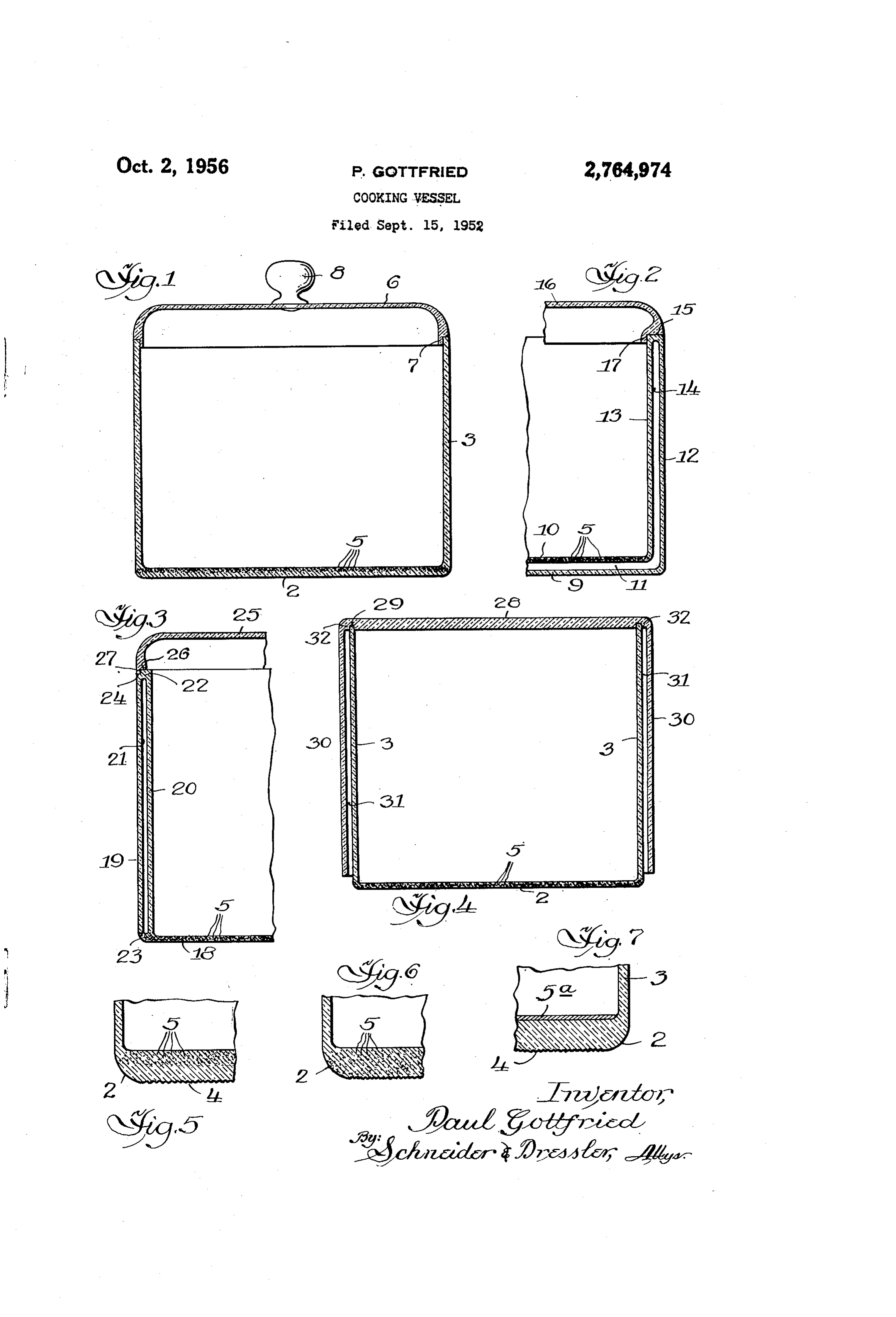
Fig. 5 is an enlarged fragmentary cross Sectional view
Page 1drawing sheetscan →
Page 2scan →
United States Patent Office 2,764,974 Patented Oct. 2, 1956 as a surface layer, the material preferably is a dull black material capable of withstanding heat such as a black chromate paint, a Glyptal resin graphite paint or other 2,764,974 suitable black paint, or it may be a thin layer of a con ;COOKING, WESSEL 5 ventional heat absorbing glass in either the usual green or blue color, or other material capable of converting
Paul Gottfried, Chicago, Ill., assignor to Chambers radiant energy to sensible heat. The layer is provided Corporation, a corporation of Indiana . on or adjacent the inner surface of the wall of the cook Application September 15, 1952, Serial No. 309,616 ing vessel against which the radiant energy rays are di 10 rected. It may be applied to the inner surface of the 9 Claims. (Cl. 126-390) bottom or side wall as a lining, or it may be applied as a separate member positioned adjacent the desired wall or walls.
The coloring materials described above are known and
This invention relates to a cooking vessel, and is par 5 se form no part of this invention. As is also known, ticularly concerned with a vessel having a wall or walls, perthese materials absorb radiant energy rays. In the cook preferably the bottom wall, transparent to radiant energy ing vessel of my invention, these coloring materials ab and provided with a material incorporated in said bottom, Sorb the radiant energy rays that impinge thereon and or provided as a surface on said bottom, capable of con convert them to sensible heat within the wall or walls of Verting the radiant energy entering the bottom into sensi- : the cooking vessel with maximum efficiency. ble heat within the vessel. In its preferred form, the The conversion of radiant energy rays, such as infra cooking vessel has its side, wall or walls, constructed to red rays, to sensible heat within the walls of the cook minimize the transfer of said heat by conduction from ing vessel of the present invention provides a more uni the inside of the vessel to the outside atmosphere. form distribution of heat within the vessel and causes a This application is a continuation-in-part of my co 25 greater proportion of the heat energy generated to be pending application, Serial No. 210,357, filed February utilized in cooking the food contained therein. Cook 10, 1951, now abandoned. ing is much more efficient than with either an opaque The cooking vessel constructed in accordance with the metal vessel or a completely transparent vessel. With present invention is preferably formed of glass, although an opaque metal vessel, much heat is lost by conduction it may be formed of transparent plastic material or other 30 through the walls of the vessel. With a completely trans material that will not interfere with the transmission of parent vessel, the radiant energy rays are converted to radiant energy rays, such as infra-red rays, therethrough, sensible heat upon striking the food to be cooked which and will be capable of withstanding the heat encountered is contained within the vessel, and as a consequence, during cooking. The cooking vessel is so positioned in the cooking is affected to a great extent by the color use relative to the source of the radiant energy rays that and shape of the food, so that accurate control of the these rays pass through the walls of the cooking vessel cooking is difficult to achieve. and impinge on the material designed specificially to The cooking vessel may be provided with a double convert the radiant energy rays to sensible heat. The radiant energy rays may be generated by gas-fired infra vessel,structure wall to provide dead air insulation around the red sources, such as gas-fired refractory material, by elec 40 the surroundingreducing thereby the heat loss by conduction to atmosphere and increasing cooking effi tric resistance wire or by reflector lamps which direct ciency. The double-wall structure may be applied to the the rays in a concentrated beam against the bottom and/or bottom and side wall or walls of the vessel, or to either. side wall of the cooking vessel. Where the radiant energy The dead air insulating space may be provided around rays are directed against the side wall, that wall should the side walls by having side walls depend from the top have a construction similar to the bottom wall. Prefer ably the outer surface of the portion of the cooking vessel cover for the cooking vessel. The structure by means of which the above and other against which the radiant energy rays are directed is advantages of the invention are attained will be described rough-finished to decrease reflection of the rays directed in detail in the following specification taken in conjunc thereagainst.
A material capable of converting radiant energy to 50 tion with the accompanying drawings, showing preferred illustrative embodiments of the invention, in which:
sensible heat is incorporated in or on the wall of the Figure 1 is a cross sectional view through a cooking cooking vessel against which the radiant energy rays are vessei embodying the present invention; directed. This wall is preferably the bottom wall, but it Fig. 2 is a fragmentary cross sectional view through is obvious that the sources of the radiant energy rays another embodiment of the invention, showing a cooking could be arranged to send the rays through the side wall 55 vessel having a double-wall bottom and side wall struc of the vessel or through both the bottom wall and the ture;
side wall.
The material capable of converting radiant energy rays vessel Fig. 3 is a view similar to Fig. 2, showing a cooking to sensible heat within the vessel is a coloring material having a bottom of single thickness and a double which may be incorporated in the wall itself or applied 60 wallFig.side4 construction;
is a cross sectional view of another embodiment as a surface layer to the wall. When incorporated in a wall of the cooking vessel, the coloring material is pref of the invention showing a cooking vessel provided with a top cover having depending side walls to form an in erably positioned in the portion of the wall adjacent the sulating interior although it may also be incorporated throughout vessel; dead air space surrounding the side walls of the the entire thickness of the wall. 65
Fig. 5 is an enlarged fragmentary cross Sectional view
When so positioned, the coloring material which is of the lower corner structure of a cooking vessel embody preferred may be any suitable material, preferably a ing the present invention and showing the cooking vessel black material, known in the art to color glass, or other transparent materials, for example, carbon. Other color bottom provided with a rough finish to decrease reflection ing materials, for example, salts having colored cations 70 of radiant energy rays impinging thereon and showing a such as copper nitrate, nickel nitrate or cobalt nitrate coloring material capable of converting radiant energy into may be used to produce various colors. When applied sensible heat incorporated in a portion of the bottom wall;
Page 3scan →
3. A.
Fig. 6 is a view similar to Fig. 5 wherein the coloring 5a may be applied to bottom 2 as a coating or lining material is incorporated throughout the entire bottom or it may be applied as a separate member positioned wall; and within cooking vessel immediately above the bottom. Fig. 7 is a view similar to Fig. 5, of another form of Layer 5a may comprise a coating of black paint or any construction, wherein the coloring material is applied as suitable material that will convert radiant energy rays to a layer adjacent the inner surface of the botton. sensible heat. A dull black surface is preferred. The In the drawings, the reference numeral 2 indicates the positioning of coating 5a within the cooking vessel causes bottom of a cooking vessel having an upstanding side wall the conversion of the radiant energy rays to sensible heat 3. The vessel shown has a conventional circular side waii, to take place within the cooking vessel. If the source of but it may have any desired shape. The bottom may be O radiant energy rays is directed against a side wall, layer of any Suitable material that is substantially transparent Sa will be positioned on the inner Surface of the side wall. to radiant energy rays and the side wall may be cf the A top cover 6, made of the same material as the cook Same material or other suitable material. One such suit ing vessel or other suitable material, is dimensioned to able material is glass, such as a heat-resistant glass manu fit over the upper edge of side wall 3 and is provided with factured by the Corning Glass Works under the trade a depending flange 7 fitting within the wall to help retain mark “Pyrex,” which is desirable because if pernits the the heat within the cooking vessel. A handle 8 is secured passage of radiant energy rays and is capable of with to top cover 6 in any suitable manner.
standing the conditions encountered in cooking. Where The embodiment of the invention illustrated in Fig. 2 it is desired to employ a material having an extremely low is essentially similar to the embodiment previously de coefficient of expansion which will withstaad great ther 20 scribed except that the bottom comprises a pair of walls mal shock, a treated borosilicate glass of the type dis 9 and 10 spaced to provide a dead air space there closed in Hood et al. Patent No. 2,106,744, granted Febru between and the side wall comprises a pair of walls 12 and ary 1, 1938, may be used. Other suitable materials such 13 spaced to provide a dead air space 4 therebetween. as transparent, heat-resistant plastic are also satisfactory. The dead air space 4 connects with dead air space 1 The cooking vessel illustrated in Fig. 1 is designed to so that the cooking vessel is substantially surrounded by be positioned with its bottom 2 above a source of infra-red the dead air insulation sealed in place as indicated at 5. rays, Such as gas-fired incandescent refractory material or The spaces 1 and 14 may be evacuated, if desired. The infra-red reflector lamps. It is preferred, therefore, that top cover 16 fits over the upper edge of side walls 2 bottom 2 be rough-finished on its outer surface, as indi and 13 and has a flange 7, similar to flange 7, fitting cated at 4, to decrease reflection of radiant energy rays within side wall 13. The material capable of converting directed thereagainst. The entire outer surface of the radiant energy into sensible heat is incorporated in inner cooking vessel may be rough-finished, if desired. wall 10 to obtain maximum conversion of the radiant A material 5, capable of absorbing impinging radiant energy to sensible heat within the vessel and closely adja energy rays and converting them to sensible heat is in cent the interior of the vessel. The outer surface of the corporated in bottom wall 2 as shown in Figs. 1-6. Ma 3. 5 cooking vessel is preferably rough-finished, as in the pre terial 5 may be carbcn or other suitable coloring material. viously described embodiment, over the area against which The coloring material is preferably incorporated in a por the radiant energy rays are directed, to decrease the re tion of the bottom wall adjacent the interior surface of the flection of the radiant energy rays.
vessel, as shown in Figs. 1 and 5, so that the radiant The cooking vessel shown in Fig. 3 has a bottom 18 energy rays will pass through the uncolored portion and of single thickness and a side wall comprising spaced walls will be converted into sensible heat within the vessel wails 9 and 20 having a dead air space 21 sealed therebetween, and adjacent the interior of the vessel with attendant in as indicated at 22 and 23. As in the case of the embodi creased efficiency. In this position the coloring material ment illustrated in Fig. 2, the space 2 may be evacuated, does not come into contact with the contents of the if desired. The upper edge 22 of the side wall is recessed, vessel. si 5 as indicated at 24, and the top cover 25 has its lower The coloring material may be incorporated throughout edge 26 recessed, as indicated at 27, to fit against the the entire thickness of a wall, as shown in Figs. 2, 3, 4 recessed portion 24. The coloring material 5 and the and 6. This form of construction also serves to convert rough finish on the outer surface of the cooking vessel radiant erasergy to sensible heat within the walls of the in this embodiment of the invention are the same as in vessel and adjacent the interior of the vessel to provide 50 the other embodiments.
greater cooking efficiency than is possible with conven In the embodiment of the invention illustrated in tional opaque metal vessels or colorless transparent ves Fig. 4, the cooking vessel is a substantial duplicate of the sels. Material 5 need not be positioned in botton wall 2, vessel shown in Fig. 1 and the same reference numerals but it may be positioned in side wall 3 if the source of are used to denote corresponding parts. A top cover radiant energy rays is arranged to direct rays against the 28, recessed as indicated at 29, fits over the top edge side wall. in this case, the outer surface of side wall 3 of side wall 3. Cover 28 projects slightly beyond side is preferably rough-finished. wall 3 and is provided with a depending side wall 30 Coloring material 5 may be incorporated in the glass which extends substantially the entire height of side wall or other suitable material in manners well known in the (54) 3 and is concentrically spaced therefrom to form a space art. Where a borosilicate glass of the type disclosed in 3 which is designed to limit or prevent movement of Patent No. 2,106,744 is employed, the glass may be the air trapped therein. A portion of the heat generated colored as disclosed in the patent to Nordberg et al. by the conversion of radiant energy within the cooking 2,303,756, granted December 1, 1942. As therein de vessel warms the air in Space 35, and since the top end scribed, the glass may be colored by adding a suitable of the Space is sealed, as indicated at 32, the warm air coloring material while the glass is in the porous State cannot be displaced by air from the surrounding atmos and the coloring matter is periinanently sealed in the glass phere. Accordingly, Space 31 is substantially a dead air after firing. Penetration of the coloring material to the Space even though it is not sealed at its bottom edge. desired thickness may be controlled as described in Pat As in the case of the other embodiments of the invention, ent No. 2,303,756. The coloration imparted may serve the outer surface of the vessel is rough-finished over the as decorative function as well as the function of convert area against which the radiant energy rays are directed, ing radiant energy rays to Sensible heat. to facilitate the most efficient transmission of radiant Instead of incorporating the coloring material in the energy into the walls of the cooking vessel, and coloring wall itself, the coloring material may be applied as a layer material 5 is incorporated in the bottom wall to con 5a (Fig. 7) adjacent the inner surface of bottom 2. Layer vert the radiant energy into sensible heat within the ves 4 sel. A handle, similar to handle 8, may be provided walls, at least one of said walls being of a material sub on this cover. stantially transparent to radiant energy rays, and a colored Although the cooking vessel in each of the embodi material capable of absorbing radiant energy rays, said ments is described as having its bottom and side wall of colored material being positioned interiorly of a por the same material, it will be understood that they may tion of one of said substantially transparent walls adja be formed of different materials, the essential require cent the inner surface thereof, whereby radiant energy ment being that the portion of the vessel against which rays transmitted through the substantially transparent the radiant energy rays are directed be capable of per wall containing said colored material are converted by mitting such rays to enter and be converted to sensible said colored material to sensible heat within said cook heat with maximum efficiency. It is of course preferred O ing vessel.
that the entire vessel be designed to minimize the loss 6. A cooking vessel having a bottom wall and side of heat by conduction to the atmosphere. walls, at least one of said walls being of a material sub While I have described preferred embodiments of my stantially transparent to radiant energy rays, a colored invention in considerable detail, it will be understood lining capable of absorbing radiant energy rays, said that the description thereof is intended to be illustrative, 5 colored lining being positioned on the inner surface of rather than restrictive, as many details may be modified or one of said substantially transparent walls, whereby radi changed without departing from the spirit or scope of ant energy rays transmitted through the substantially the invention. Accordingly, I do not desire to be re transparent wall having said colored lining are converted stricted to the exact structure described. by said colored lining to sensible heat within said cooking I claim: 20 vessel.
1. A cooking vessel having a bottom wall of a ma 7. A cooking vessel as recited in claim 4 in which the terial substantially transparent to radiant energy rays outer surface of the substantially transparent wall con and a poor conductor of sensible heat, and a material taining said colored material is rough-finished to minimize capable of absorbing radiant energy rays, said material the reflection of radiant energy rays directed thereagainst. capable of absorbing radiant energy rays being positioned 25 8. A cooking vessel as recited in claim 4 which has adjacent the inner surface of said bottom wall so that outer side walls of substantially transparent material infra-red rays entering said bottom wall impinge on said spaced from and surrounding the side walls to form a material capable of absorbing radiant energy rays and are double walled structure to insulate said vessel and mini converted thereby into sensible heat within said vessel.
2. Accoking vessel having a bottom wall of a ma 30 mize the loss of sensible heat by conduction to the at mosphere.
terial substantially transparent to radiant energy rays 9. A cooking vessel as recited in claim 4 which has an and a poor conductor of sensible heat, and a material outer shell of substantially transparent material, said outer capable of absorbing radiant energy rays, said material shell being spaced from the side walls and bottom wall capable of absorbing radiant energy rays being positioned to form a double walled structure to insulate said vessel interiorly of a portion of Said bottom wall adjacent the 35 and minimize the loss of sensible heat by conduction inner surface thereof so that infra-red rays entering said to the atmosphere.
bottom wall impinge on said material capable of ab sorbing radiant energy rays and are converted thereby References Cited in the file of this patent into sensible heat within said vessel. UNITED STATES PATENTS 3. A cooking vessel having a bottom wall of a ma 40 terial substantially transparent to radiant energy rays 629,122 Davis ----------------- July 18, 1899 and a poor conductor of sensible heat, and a layer of 1,413,063 Sailer ----------------- Apr. 18, 1922 material capable of absorbing radiant energy rays, said 1,466,941 Houze ---------------- Sept. 4, 1923 layer of material capable of absorbing radiant energy 45 1497,764 Simonson et al. -------- June 17, 1924 rays being positioned on the inner surface of said bottom 1,549,743 Bultman et al. ---------- Aug. 18, 1925 wall so that infra-red rays passing through said bottom 1,553,617, Katzinger ------------- Sept. 15, 1925 wall impinge on said material capable of absorbing radiant 1,757,989 Acton ---------------- May 13, 1930 energy rays and are converted thereby into sensible heat 1,880,358 Payson et al. ------------ Oct. 4, 1932 within said vessel. 2,122,821 Mohr ----------------- July 5, 1938 4. A cooking vessel having a bottom wall and side 50 2,213,894 Barry ----------------- Sept. 3, 1940 walls, at least one of said walls being of a material sub 2,315,475 Cobb et al. ------------- Mar. 30, 1943 stantially transparent to radiant energy rays, and a colored 2,391,660 Ward ------------------ Dec. 25, 1945 material capable of absorbing radiant energy rays, said 2,462,728 Debs ------------------ Feb. 22, 1949 colored material being positioned adjacent the inner sur 55 2,511,404 Glenkey et al. ---------- June 13, 1950 face of one of said substantially transparent walls, where by radiant energy rays transmitted through the substan FOREIGN PATENTS tially transparent wall containing said colored material 336,029 Germany -------------- Apr. 21, 1921 are converted by said colored material to sensible heat 724,819 France ---------------- Jan. 30, 1932 within said cooking vessel. 873,890 France ---------------- Apr. 13, 1942 5. A cooking vessel having a bottom wall and side 60
Provenance
- Collection
- Patents citing this work
- Pages
- 4
- Method
- pdftotext (the PDF's own text layer) + pdftoppm 300dpi page scans
- Patent office record
- patents.google.com →
- Source
- Google Patents citing-documents table
- Assignee
- Chambers Corp
- Published
- 1956-10-02
- Transcribed from
- patentimages.storage.googleapis.com →