

patent · US2818112A
Gas burners
31 December 1957
Text
Drawings
Page 1drawing sheetscan →
Page 2scan →
Gas burners
Frank W. Wedlick and Felix A. Tyrone, Denver, Colo., assignors to Killan Gas BurneriCo., Denver, Colo.
This invention relates to a gas burner, and has for its 5 principal object the provision of a burnier which will main tain a pilot-flame about the peripheral surface of a stream of combustion gases flowing to a main flame, regardless of the velocity of flow, so that the main flame will be 20 self-igniting-in case of "blowouts.”
Other objects and advantages reside in the detail con struction of the invention, which is designed for simplicity, economy, and efficiency. These will become more ap parent from the following description.
In the following detailed description of the invention, 25 reference is had to the accompanying drawing which forms a part hereof. Like numerals refer to like parts in all views of the drawing and throughout the description. In the drawing:
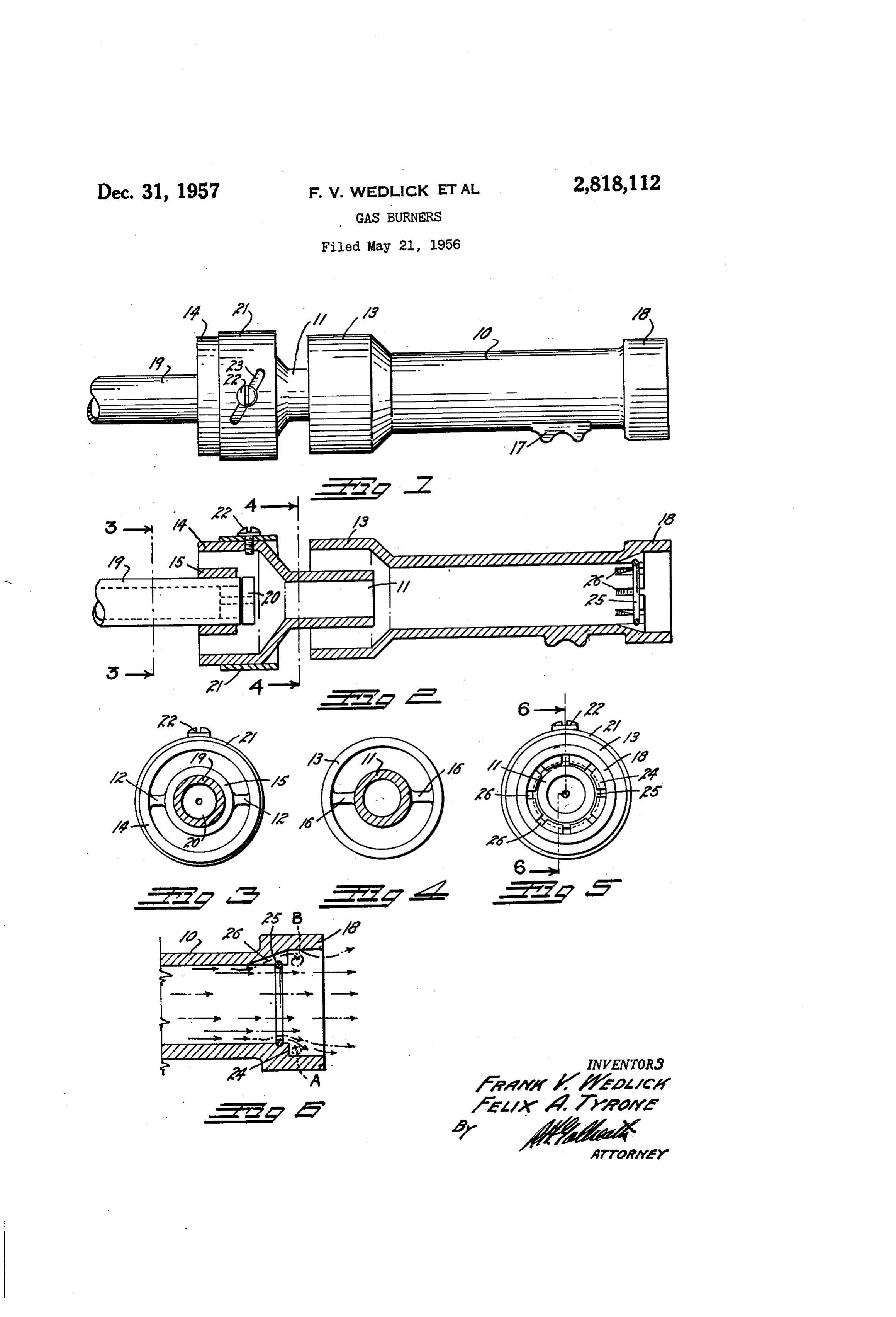
Fig. 1 is a side view of the improved gas burner; 30 Fig. 2 is a longitudinal section therethrough; Fig. 3 is a cross-section, taken on the line 3-3, Fig. 2; Fig. 4 is a cross-section, taken on the line 4-4, Fig. 2; Fig. 5 is a front end view of the improved burner; and Fig. 6 is an enlarged, fragmentary, diagrammatic, lon 35 gitudinal section through the forward extremity of the improved burner illustrating the gas flow therethrough. The improved burner comprises a unitary casting formed to provide an elongated cylindrical mixture tube 10 formed integrally with a concentric fuel discharge tube 40 11. The discharge tube terminates at its rear extremity in a first primary air bell 14 within which a spud collar 15 is supported upon suitable supporting arms 16. The discharge tube 11 is supported upon radially extending supporting arms 12 cast within a second primary air bell 45 13 which is formed on the rear extremity of the mixture tube 10. The bells 13 and 14 correspond in diameter and the discharge tube 11 is of smaller diameter than the mix ture tube 10 and extends into close proximity to the rear extremity of the mixture tube. 5 The mixture tube is provided with a conventional foot boss 17 by means of which it may be supported upon any suitable supporting structure. The forward extremity of the mixture tube 10 terminates in an enlarged circular flame cup 18. The mixture tube 10, the discharge tube 55 11, the air bells 13 and 14, the spud collar 15, and the cup 18 are all cast integrally as a single complete unit. Gas is supplied to the burner through a conventional pipe spud 19 positioned within the spud collar 15 and termi nating in a gas orifice bushing 20, as is conventional in 60 gas burners.
It can be seen that a jet of gas discharging from the orifice bushing 20 will exert a venturi effect in the first belt 14 and discharge tube 1 so as to draw primary air through the bell 4 and through the tube 11 and intermix the air with the gas in the discharge tube 11. It can also be seen that the rapidly flowing stream of gas and intermixed air discharging from the tube 11 into the mixture tube 10 will also exert a venturi effect to draw additional primary air through the second air bell 13 about 70 the discharge tube 11 and intermix this additional air with prior intermixture in the mixture tube 10 to produce an intimately mixed combustible mixture which will be dis charged at relatively high velocity through and from the flame cup 18.
The amount of primary air entering the second primary air bell 13 can be regulated and pre-set by means of a cylindrical damper band 21 which is slidably fitted about the first air bell 14, and which can be moved toward the second air bell 13 to control the space between the band 21 and the bell 13'so as to regulate the amount of airen tering the second bell 13.
The damper band can be adjusted in any desired man ner. As illustrated, it is provided with a clamp screw 22 threaded into the bell 14 and extending through a diag onal slot 23 in the band 21. It can be seen that by loosen ing the screw 22 the band may be rotated to urge it for wardly or rearwardly in consequence of the incline of the slot 23: When the proper adjustment has been reached, the damper band can be locked in adjusted position by tightening the screw 22.
In conventional gas burners the velocity of the fuel mixture discharging from the mixture tube will occa sionally be sufficient to force the flame or combustion zone away from the discharge extremity of the tube suf ficiently far to extinguish the flame. It is then necessary to re-ignite the flame by means of a suitable pilot light or other means.
In this improved burner, however, the flame cup 18 is provided with an enlarged bore exceeding the internal diameter of the mixture tube 10. This enlarged bore will act to decrease the velocity of the gas stream, at the cylindrical surface of the latter, and within the cup 18 so as to tend to retain an annular flame about the dis charge of the cup at all velocities. To assist in the flame retention, a relatively flat, sharp-cornered shoulder 24 is formed joining the inner wall of the cup to the inner wall of the mixture tube 10 and the inner wall of the mixture tube adjacent the shoulder 24 is annularly indented to re ceive a round resilient wire "eddy' ring 25. The ring 25 is installed by contracting it and forcing it into the ex tremity of the tube 10 until it snaps in place in the groove therein, as shown in Figs. 2 and 6. The groove is suffi ciently shallow so that the ring 25 projects into the mix ture tube 10 for approximately one-half the diameter of the wire of which the ring is formed. The protruding ring forms an annular, semi-cylindrical protuberance or obstruction completely around the discharge throat of the mixture tube in close proximity to the shoulder 24. The result is the outer layer of the rapidly traveling core of fuel mixture will be caused to sweep first toward the axis of the flame tube, thence outwardly through the enlarged bore in the cup 18, creating an annular vacuum pocket, such as indicated at "A' in Fig. 6, entirely around the burner discharge. This vacuum pocket will attract fuel mixture from the surface of the core of traveling fuel, and this attracted fuel mixture will swirl in an ignited, annular eddy current, somewhat similar to a conventional "smoke ring,' throughout the entire circumference of the bore in the flame cup 18, such as indicated by the swirling arrow
This swirling ring of low velocity fuel mixture forms a constant annular combustion zone around the entire inner periphery of the cup 18, regardless of the velocity of the fuel mixture flowing directly from the mixing tube 10. This annular flame will act as the pilot light, should the main flame become extinguished, to immediately re-ignite the atter.
It has been found that the efficiency of this annular pilot light flame can be greatly increased by cutting or casting a plurality of inclined slots 26 in the inner wall of the mixture tube 10 at its forward extremity. The slots 26 extend beneath or behind the "eddy" ring 25 and act to conduct fuel mixture below the ring and to the pocket
Page 3scan →
"A," as indicated by the swirl “B” in Fig. 6, so as to in crease the efficiency of the combustion in the annular pilot fame pocket.
In actual use the velocity of the gas can be increased until it forces the main flame forwardly of the cup 18. It will be observed, however, that a ring type pilot flame completely surrounds the edge of the cup at all times ready for immediate re-ignition should a "blowout" of the main flame occur.
While a specific form of the improvement has been de O scribed and illustrated herein, it is desired to be under stood that the same may be varied, within the scope of the appended claims, without departing from the spirit of the invention.
Having thus described the invention, what is claimed 5 and desired secured by Letters Patent is:
1. In a gas burner, an elongated tube for the advance ment of a gaseous fuel mixture; an enlarged flame cup formed on the discharge extremity of said tube to reduce the velocity of said mixture prior to discharge; an abrupt, 20 rectangular, internal shoulder joining said tube to said cup; an internal, annular ring groove formed in the in ternal surface of said tube adjacent and parallel to said shoulder; an expansible wire ring expanded into said groove; and a plurality of slots formed in said shoulder 25 forming spaced passages between said tube and said flame cup and behind said ring.
2. In a gas burner, an elongated tube for the advance ment of a gaseous fuel mixture; an enlarged flame cup formed on the discharge extremity of said tube to reduce the velocity of said mixture prior to discharge; an abrupt, rectangular, internal shoulder joining said tube to said cup; an internal, annular ring groove formed in the inter nal surface of said tube adjacent and parallel to said shoul der; an expansible wire ring expanded into said groove; said groove being sufficiently shallow so that said ring will project internally into said tube for approximately one half the diameter of the wire from which it is formed to form an annular, semi-cylindrical protuberance com pletely around the discharge throat of said tube; and a plurality of slots formed in said shoulder forming spaced passages between said tube and said flame cup and behind said ring.
References Cited in the file of this patent
United states patents
Foreign patents
Provenance
- Collection
- Patents citing this work
- Pages
- 3
- Method
- pdftotext (the PDF's own text layer) + pdftoppm 300dpi page scans
- Patent office record
- patents.google.com →
- Source
- Google Patents citing-documents table
- Assignee
- Killam Gas Burner Co
- Published
- 1957-12-31
- Transcribed from
- patentimages.storage.googleapis.com →