

patent · US2935840A
Fluid mixing chamber
10 May 1960
Text
Drawings
Page 1drawing sheetscan →
Page 2drawing sheetscan →
Page 3drawing sheetscan →
Page 4drawing sheetscan →
Page 5scan →
United States Patent Office 2,935,840
2,935,840. pressure distribution at the inlet end which has a high pressure adjacent the tubular wall and a low pressure ad
Fluid mexing chamber
Fritz Schoppe, Munich-Pasing, Germany, assignor to jacent the axis of the tubular chamber. This fluid moves toward the other end and as the fluid stream progresses
Metallbau Semler GmbH.- Munich, Germany, a Ger to the other end the pressure gradient profile flattens. The man company. flatter pressure gradient approximate the other end re Application February 26, 1954, serial No. 412,859 Sults in a low pressure at the axis of the tubular chamber Claims priority, application Germany February 26, 1953 which nevertheless is higher than the pressure at the axis of the first end, and this resultant pressure differ ;: 17 Claims. (C. 60-35.6) 0. ential causes a backflow in the nature of a counterflow This invention relates to method and appartus for mix along the axis of the chamber from the other end to the ing fluids. Such method and apparatus, which involve a first end. The outer zone of fluid and counterflowing mixing chamber, can be utilized in many mixing applic inner zone of fluid provide substantially parallel fluid cations and is hereinafter particularly described related streams. Interaction between the counterflowing inner to use in combined mixing and combustion in which a 5 and outer Zones, when the Reynolds number parameter continuous flow of a first medium, e.g., combustive, is exceeds the minimum required to obtain the S-L type of mixed with at least a second medium, e.g., combustible, turbulence, gives rise to an annular zone, between the in - whereupon the mixture, e.g., burnt gases, is permitted ner and outer Zones, of continuously violent turbulence to escape in a continuous flow from said chamber. extending lengthwise along the chamber. Additional To obtain a thorough mixing in such a mixing chamber, 20 fluid media can be also introduced into the chamber. it is indispensable that some kind of turbulence be cre This method and practical structural applications: by ated in the fluid within the chamber. For example, in which the resultant mixing action can be used are de previously known combustion chambers, turbulence in scribed hereinafter in the detailed description portion the fluid is conventionally created by one or more ob of this application. . . .. . . .. stacles, either rigid or constituted by jets of an auxiliary 25 Because of the inherent characteristics of the S type fluid. These obstacles have the inherent drawback of of turbulent flow it will occur between parallel streams. creating one or more zones of "dead water' and, hence, a even at an infinite Reynolds number whereas flow past considerable loss of energy. The term "dead water" is an obstacle (Blasius type of flow) is stable beyond a known to designate a fluid which is not in proper circu finite range of Reynolds numbers (i.e., mixing becomes : lation, and as used herein applies to a fluid which is not 30 impossible in a mixing chamber, and in a combustion in proper circulation in a mixing chamber. chamber burning cannot be maintained with Blasius type Specific described applications of the invention herein flow above a certain Reynolds number). Because pre disclosed apply to combustion chambers. Major prob viously known combustion chambers have depended upon lems of combustion-chamber design are (1) proper mix 35 the Basius type flow and turbulence resulting therefrom, ing of the gases; (2) flame stabilization; (3) clean.com the upper limit of air flow in the chambers known prior bustion; (4) elimination of pulsations and noise; (5) re to this invention was the aforenoted 400 feet per second duction of pressure loss; and (6) maintenance of steady and, as this speed was so close to stable flow (with no. controlled fuel flow. Gas velocities in the combustion turbulence), designers were restricted to input airflow zone of previously known combustion chambers have been values well below 400 feet per second. A combustion reported as high as 400 feet per second, but they are 40 chamber utilizing the present invention has no known commonly held to 150 to 250 feet per second or below. upper speed limit of input air flow because an excellent . This invention used in conjunction with a combustion unstable flow (with violent turbulence) can be main . . . chamber substantially reduces the noise level and effec tained up to values approaching infinite Reynolds num tively reduces and in some instances eliminates the afore ber. The fluids are always completely mixed in the float noted problems. - 45 ing turbulent Zone between the high speed practically par This invention encompasses a method by which, and allel streams of fluid. In combustion chambers the float a mixing chamber in which, required turbulence for mix ing positive occurrence of the turbulent mixing ensures ing is obtained without any obstacle of any kind in the an even, annular flame stabilization at all input airflow inner space of the mixing chamber. A completely differ speeds excepting those of very low Reynolds numbers, ent type of turbulent flow which occurs between parallel 50 somewhere below 50. Also in a combustion chamber streams of fluid is accomplished by, and utilized in, this this complete mixing process and stabilization of flame invention. This turbulent flow, for purposes of this ap results in clean complete combustion. There is no prob plication, can be termed the Schlichting-Lessen or S-L len with pressure losses because requisite operating pres type flow, and is discussed and computed theoretically in Sures are self-induced by action of the input airflow as N.A.C.A. Report 979 published in 1950 and entitled “On 55 it passes into and along the combustion chamber. In , Stability of Free Laminar Boundary Layer Between Par this chamber although, pressure changes are necessary allel Streams" by Martin Lessen. Although the S-L type for operation the pressure loss is low and is only a frac of turbulence and various of its characteristics have been tion ef the pressure losses which occur in previously described and computed theoretically by Lessen, it has known combustion chambers and other turbulent mix never, prior to this invention, been intentionally created 60 ing chambers. Maintenance of steady, closely controlled by man. For counterflowing parallel fluid streams, Les fuel flow, while still desirable in order to maintain tur sen has calculated theoretical flow stability and instability bine blade temperature limits and combustion loads for The present invention accomplished the S-L type tur desired output, for instance, is no longer a critical prob bulence, previously known only in theory and possibly in 65 because thereasiscombustion lem insofar chamber walls are concerned no difficulty with high burning tempera nature, between parallel streams of fluid within a tubular tures destroying chamber walls. In other words, thé chamber. The method of producing these parallel outer Zone of high speed fluid maintains the chamber streams, interacting in the required manner, consists of the walls sufficiently cool that there is no danger of melting introduction of a fluid medium (in this application the the chamber walls even if common sheet metal walls are term "fluid" is intended to include liquids, gases and pull 70 used. Because of the even, coherent and annular tur verulents and combinations thereof) into the chamber bulent zone, pulsations are eliminated and noise is sub approximate one end in such a manner as to create a stantially reduced,
Page 6scan →
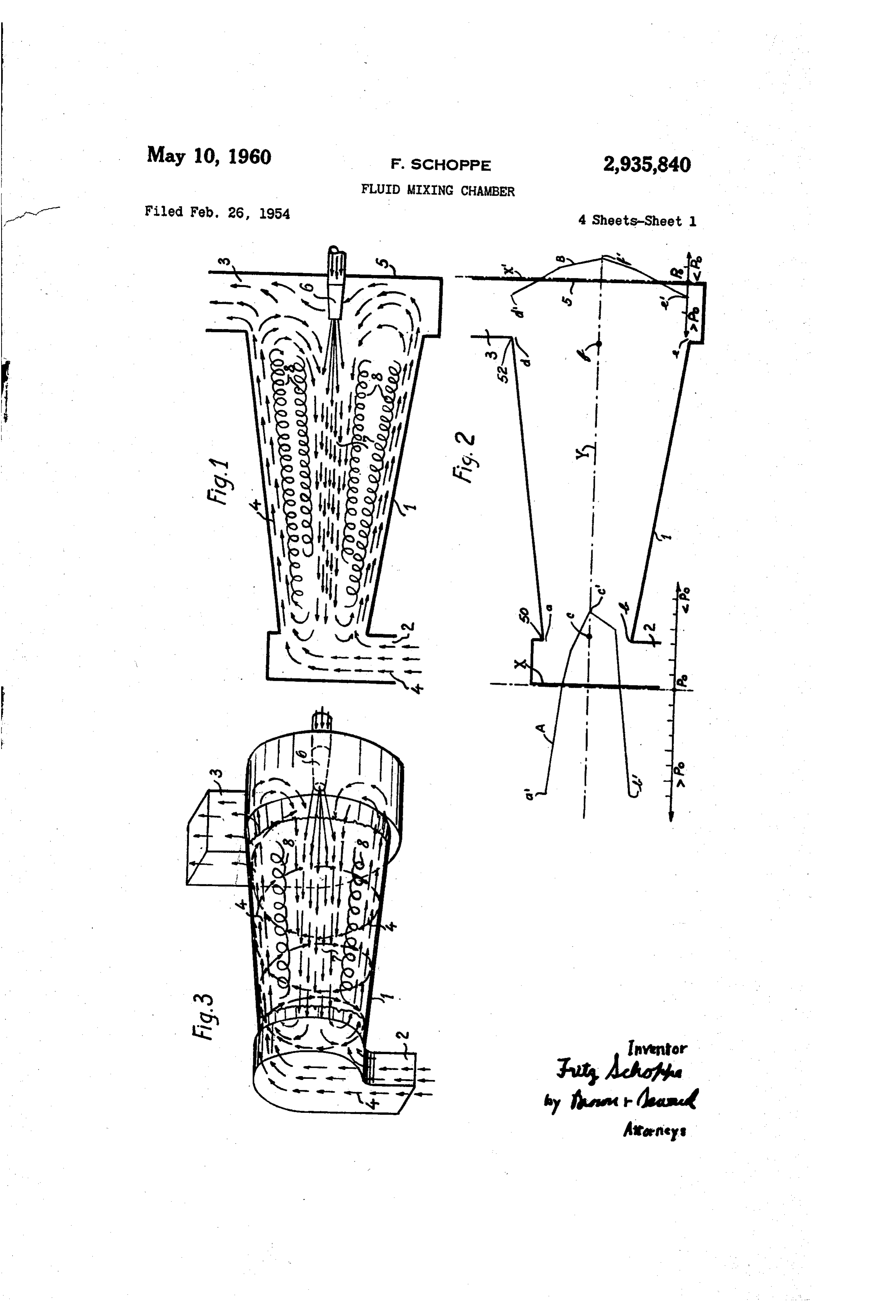
Accordingly a primary object of this invention resides scription, discussion and the appended claims taken in in providing a novel method of bringing about turbulence conjunction with the accompanying drawings, showing between parallel or approximately parallel fluid flow preferred structures and embodiments, in which: paths. Figure 1 is a longitudinal sectional view of a mixing Another object resides in providing a novel method of chamber according to the invention; creating a relatively stationary annular elongate Zone of Figure 2 is a diagrammatic showing of the distribution violent turbulence at the boundary zone between two of pressures in said chamber;
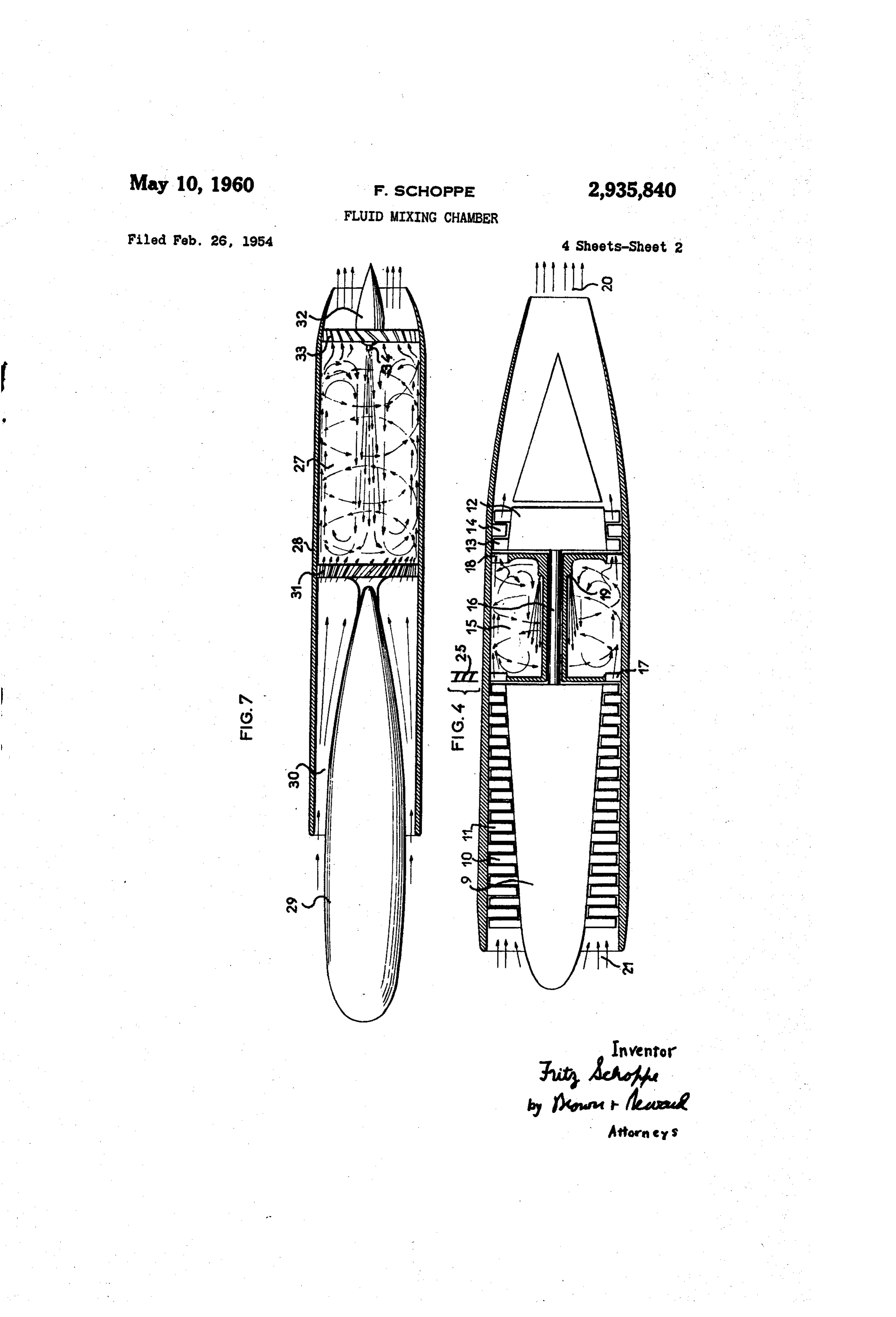
concentric, annular, elongate counterflowing fluid streams. Figure 3 is a perspective view of said chamber; Still another object resides in providing a novel method Figure 4 is a longitudinal sectional view of a turbo of creating a turbulent zone of fluid between two ap 0 jet engine provided with an annular combustion chamber proximately parallel fluid flow streams by creating a according to the invention;
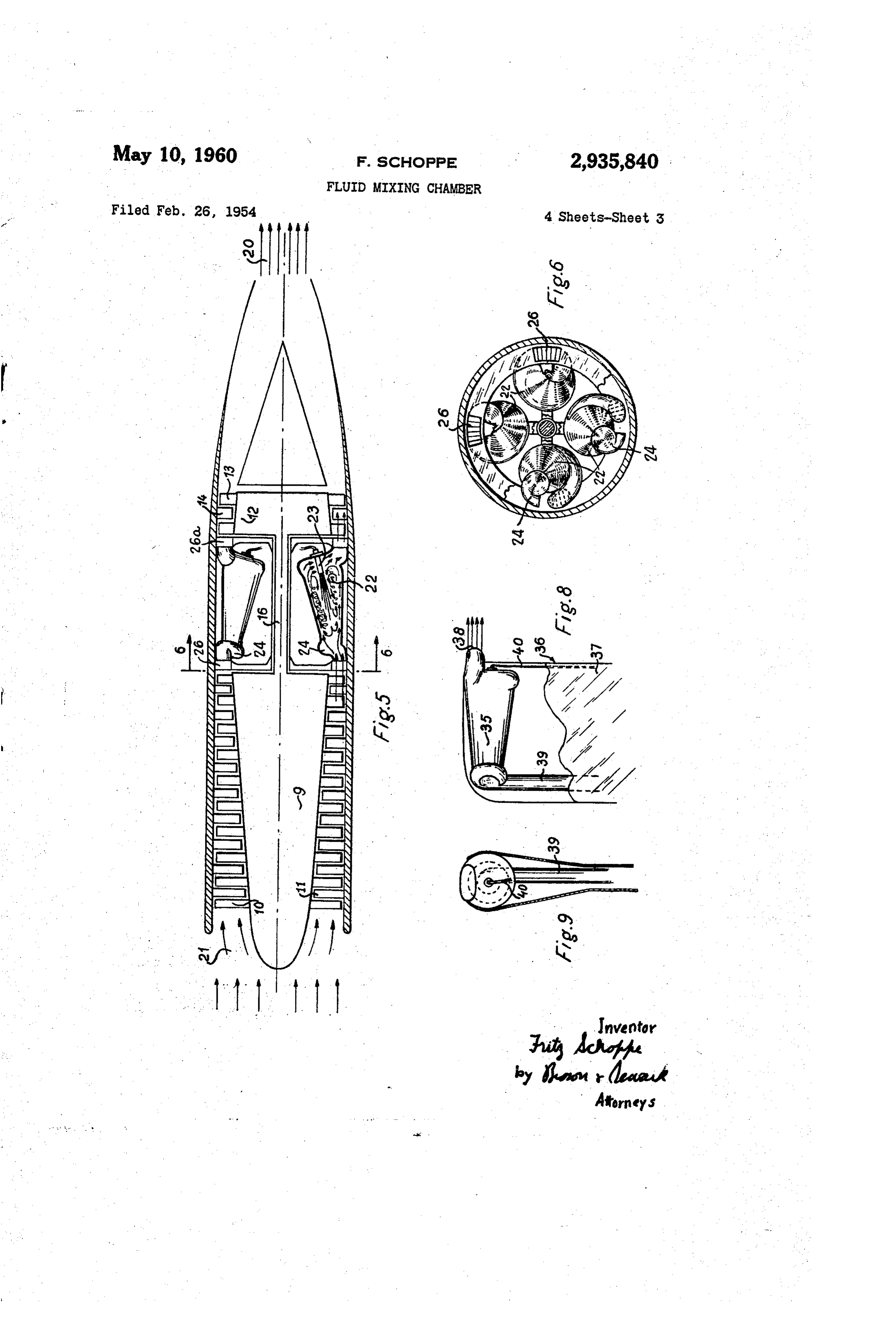
spiral fluid flow, confining the spiral flow to a fixed tubu jetFigure 5 is a part sectional view of another turbine engine provided with a plurality of combustion cham lar path, and at a distance. down the path enabling a re versal in the form of an inflow becoming a counterflow bers of the types of Figures 1 to 3 angularly spaced of some of the fluid along the axis on the innerside of the 15 around the axis of the engine;
spiral outer flow. - Figure 6 is a cross-sectional view along line 6-6 of A further primary object resides in the provisions of Figure 5;
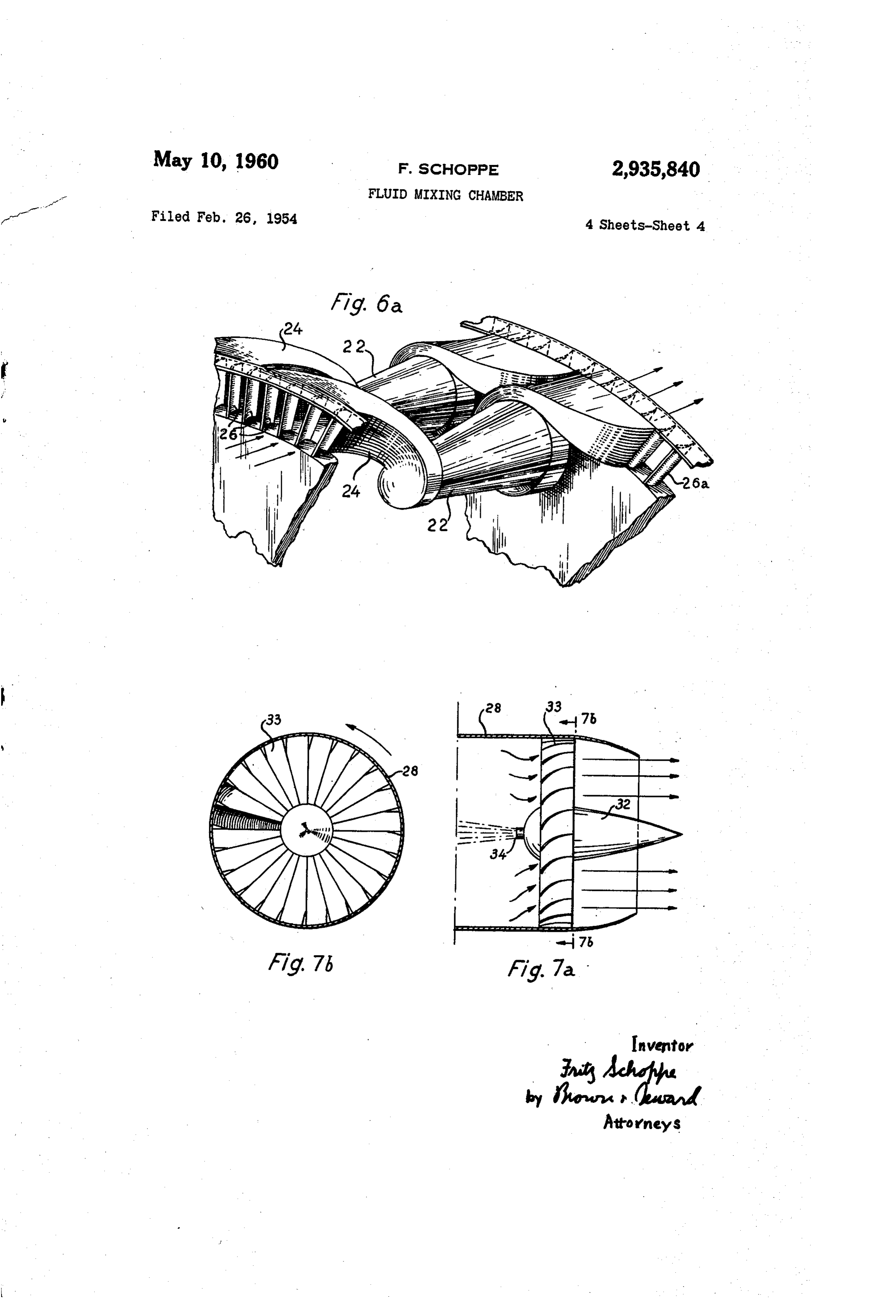
a novel mixing chamber in which a relatively stationary Figure 6a is a perspective view of two combustion confined zone of turbulence is obtained through the chambers having the form illustrated in Figures 5 and 6; interaction of approximately parallel opposite flow paths 20 Figure 7 is a longitudinal sectional view of a ram-jet created in the chamber. provided with a combustion chamber according to the A still further object resides in the provision of a novel invention;
tubular mixing chamber in which an annular intermedi Figure 7a is an enlarged sectional view of the straight ate zone of turbulence is obtained between inner and ener vanes illustrated in Figure 7; outer coaxial zones of counterflowing high speed fluid 25 Figure 7b is a cross section view of the straightener flow streams by introducing and creating a spiralling in vanes taken on line 7b-7b of Figure 7a; put of fluid into one end of the mixing chamber and di Figure 8 is a diagrammatic view of a helicopter blade rected toward the other end and such a chamber can be of which the tip is provided with an individual combustion provided with a device for introducing a second fluid chamber according to the invention; and into the chamber, the resulting mixture escaping from one 30 Figure 9 is an end view of the trailing edge of the end of the chamber. helicopter blade illustrated in Figure 8. A further object resides in the provision of a novel It is to be understood that the mixing chamber ac tubular mixing chamber of cylindrical or frusto-conical cording to the invention can be used for a mixing of any shape, having one end no larger than the other end, in number of different media, the gaseous, liquid or pull which an annular turbulent zone of fluid is provided be verulent form. It is also intended to be used for re tween two concentric zones of counterflowing fluid acting together different media, and in particular for com streams within the cylindrical chamber obtained by inlet bustion purposes, as described hereunder. Various uses structure adjacent the one end of the chamber for intro of this mixing chamber with the broad aspect of reacting ducing a fluid into the chamber in a manner causing spi include such previously known uses of mixing cham ralling of the fluid in a tubular path from the one end to 40 bers as chemical reactions, heating and/or drying or cool the other end of the chamber, patterns within the cham ing of materials, moistening of materials and producing ber providing an inflow of fluid at the other end of the inert gases, among other things.
chamber and a reversal of fluid flow along the axial core As shown in Figures 1 to 3, an exemplary mixing of the chamber from the other end to the one end. chamber according to the invention is constituted by a Another object of the invention resides in the pro 45 simple tubular revolution casing 1. An inlet 2 and an vision of a mixing chamber of the type described, in outlet 3 are provided at respective ends 50 and 52 of which at least one of the media to be mixed enters at tubular casing 1. In this example, tubular casing 1 has one end, while the mixture escapes at the other end. a frusto-conical shape, inlet 2 being disposed at its small Still a further object of the invention resides in the end 50. - provision of a novel combustion chamber through which 50 According to the invention, inlet 2 is disposed, or the combustive medium passes in a continuous flow, as combined with suitable means, in such a manner that described above, and in which a combustible medium is the incoming medium (which, for example, may be a injected as near as possible along the axis of the cham combustive fluid, when the chamber is used for com ber in the direction of the axial counterflow and, prefer bustion purposes) is projected tangentially into casing 1, ably, in the vicinity of the outlet end. 55 as shown at 4, the flow thus produced always remaining Another object of my invention resides in the provision in contact with the wall of casing 1 along which it of a turbo-jet engine comprising, in combination, at least progresses while rotating (spiralling) around the axis one compressor, at least one combustion chamber of the of said casing. This spiralling progression results in a type described and at least one turbine, said turbine driv pressure distribution in the fluid in the tubular casing ing said compressor, while the same feeds said chamber 60 which enables counterflowing coaxial, annular zones of or chambers with compressed combustion supporting air fluid, Figure 1.
in a substantially helical flow, the burned gases acting on A terminal rigid obstacle, which, as shown in Figures said turbine, the rotation of which permits recovering the 1 and 2 is constituted by end wall 5 of outlet 3, can be rotational component of said burned gases, whereby the disposed transversely at the outlet end of the frusto same are ejected with a substantially rectilinear motion, 65 conical casing 1.
fuel being injected in said chamber or chambers near the Figure 2 shows a pressure distribution diagram plotted axial zone of the same. on a cross-section outline of the frusto-conical chamber A still further object of my invention resides in the pro 1. One of the pressure distribution curves A, plotted on vision of a ram-jet engine comprising a combustion cham a base line indicated by heavy line X adjacent the small ber, as described above, fed with air from outside through 70 end 50 of the chamber 4, represents the pressure distri a suitable passage as well as with fuel; the burned gases bution of the fluid at a section diametrically across the which escape from said chamber constituting the jet of Small end 50 of the frustoconical tube where the spiral the engine. fluid flow is introduced. For ease in explanation, the Further novel features and other objects of this inven value of base line X is plotted as po, the mean pressure tin will become apparent from the following detailed de- rs of the fluid within the chamber.
Page 7scan →
"The other pressure distribution curve B plotted on a Neglecting boundary layer friction along the baseline indicated by heavy line X adjacent the large end chamber at the present, the following equation for 52 of chamber 1, represents the pressure distribution stant angular momentum of the flow in the chamber will of the fluid at a section diametrically across the large end govern: - . 52 of the frusto-conical chamber 1. Here also the value M- rule of base line X is plotted as po, the mean pressure in the where:
chamber. Therefore the base lines X and X" represent M-angular momentum an identical pressure value, the mean pressure po within r-radius of the chamber . . . . . . . . the chamber. These two curves A and B are plotted at u-tangential component of the velocity of flow. different locations on the drawing figure to avoid overlap O which might be confusing. Since the angular momentum (neglecting friction) must . ... The pressure value scales of both curves A and B be constant, the tangential velocity of fluid at the inlet (extend horizontally and are divided into increments of end 50 of the chamber will be greater than its tangential equal values of pressures. No exact pressure values are velocity at the other end 52 because, in a frusto-conical indicated because these curves are intended to represent tube, r increases from the small end to the large end. differences in magnitude of the pressures at various lo The static pressure at any point in the chamber is cations in the chamber and magnitude can be shown determined by Bernoulli's law: . . . ... . . . . . . without designating exact values to the pressure scale. p%dusa constant
Mean chamber pressure po is used as a base line because sO where: : ... - it is a handy common reference pressure from which to p-static pressure in the chamber plot distribution curves of pressures at any point in the d-density of the medium.
chamber.
iReferring now to curve A, the pressure distribution of u-velocity of the flow inlet fluid, it will be seen that a very high pressure exists Since the sum of the factors of the equation m adjacent the tubular chamber wall (indicated by points 25 constant, p must be lower in a zone of high veloci a and b on the chamber wall and by a' and b' on curve higher in a zone of low velocity. At the small inle A) and a very low pressure exists at the axis Y of the of the chamber, where the velocity of the flow is high, chamber 1 (at the inlet point indicated by c on the axis the static pressure will be lower than at the large end of Y and by c' on the curve A). This is a very sharp pres the chamber where the velocity is lower. Because the sure gradient as represented by the deep bucket of curve spiral flow is confined within tubular chamber w e a and means a very large decrease of pressure, from the vortex theory suffers a modification. The low vorte: wall to the axis, exists at the inlet end 50. theory pressure at the inlet end will occur in a 'ce Referring now to curve B, the pressure distribution of zone surrounded by an outer annular zone of fluid at the large end 52 of chamber 1, it is seen that 35 pressure high speed fluid adjacent the coni the pressure adjacent the tubular chamber wall (indicated chamber wali which is developed because of centrifugal by points d and e on the chamber walls and by d" and e' forces in the spiralling fluids being confined by the tubular on curve B) is still higher than the mean pressure po, walls against outward movement. This outer Zone of but lower than the pressure a' adjacent the wall at inlet fluid under centrifugally developed pressure cannot retirn end 50. The pressure at the axis Y of the chamber 1 40 toward the low pressure zone at inlet end 50 against the (at the point indicated as if on axis Y and f' on curve centrifugal forces so the fluid in the outer annular zone B) is lower than the mean pressure po but not as low progresses along the chamber wall to the large end 50. as pressure 'c' at the center of axis of the section at inlet Near the large end because of the progressive de e end 50. This pressure gradient is flatter than the gradient in velocity of the fluid, centrifugal forces in the spiralling at the inlet end 50, although it still represents a decrease fluid can no longer keep the outer zone under a high in pressure from the wall to the axis at the large end 52. pressure against the wall of the tubular chan Fluid flows from a high pressure zone to a low pres because the vortex pressure has increased, the pre sure zone hence the incoming fluid which is under a very distribution becomes flatter as noted by curve B (Figure high pressure a' and b' in the annular zone adjacent 2) and an inflow of fluid to the center of large ... the chamber wall at inlet end 50, if it can be prevented will result. * . . . . . . .. . . . . . .
from flowing inwardly to point c (a very low pressure), Thus it can be seen that the central zone pressure at will fow along the chamber wall toward the end 52 the small inlet end is lower than the central Zone pressure where the pressure d' and e' is lower than pressure a at the large end and flow of the fluid will take place from and b'. Near the end 52 of chamber 1, as will be here the large end to the small end, in an inner Zone along the inafter explained, fluid tends to flow inwardly from the 55 axis of the chamber. ... : ...s high pressure d' and e' of outer Zone to the lower pres As shown in Figures 1 and 3, a nozzle 6 fee sure f' at the inner zone along axis Y. Fluid at the chamber with a second medium which, in the case inner zone of large end 52 along axis Y is under a pres combustion chamber, is a combustible medium, - sure f' which is higher than pressure c’ at the axis of the feeding preferably taking place, as shown, near the axis inlet end 50, hence an inner zone or core of fluid flow of the chamber in the direction of said counterflow." The will occur from end 52 to inlet end 50. 60 ideal location, particularly in the mixing of spontaneously Such a pressure pattern within the tubular chamber 1 combustible, oxidizers, and fuels, is to introduce the addi as has been described, can result in counterflowing outer high tional fluid (e.g., the oxidizer) in the inner zone at the and inner zones of fluid. pressure end of that Zone, because partic ". . . fluid could then be drawn into and mixed within the
The manner in which this pressure pattern and the 65 turbulent desired flow paths are provided will now be described. intermediate zone, throughout its entire length. As was previously described with reference to the em The additional fluid (for example, gasoline) could, of course, be introduced with the aforenoted first flui re.
bodiment of Figures 1, 2 and 3, fluid 4 is introduced example, air) in which case it becomes part of the through inlet 2 in a direction tangential to the tubular fluid. .. . . . . .. wall of chamber 1 and introduction generates a high The interaction between the flow 4 of the first medit speed spiral flow along the wall of chamber 1. The spiral and the counterflow 7 gives rise to an annular flow generated along the outer wall of the frusto-conical intense continuously violent S-L type of turb mixing chamber by the: inlet means 2 can be assumed, tween the inner and outer zones of counterflowin as a first approximation, to be a potential vortex gov This turbulence occurs between the high speed erned by the law of conservation of angular momentum, is outer zones and creates a neutral speed zone, in effect a 8 floating or stationary (suspended) zone of turbulence in rotor 9 from the turbine rotor 12. The annular inlet 17 which mixing of the turbulent fluid is thorough and, of the combustion chamber is fed with a substantially excepting for outer and innermost zones, can fill up the helical (spiral) flow of compressed air from the last row interior space of the mixing chamber. Since additional of blades of rotor 9 of the compressor, while the annular fluid is being continuously fed through the inlet 2 and outlet 18 of the combustion chamber feeds the first row thence by means of the counterflowing streams into the of blades 13 of the rotor 12 of the turbine. A suitable turbulent zone, the thoroughly mixed fluid in the turbu combustible medium is fed near the axis of the chamber, lent zone must have an exit. In the embodiment of as shown at 19, in the direction of the counterflow, Figures 1-2 the outlet is provided at the large end of the to be mixed thoroughly with the combustion support frusto-conical tube and outgoing fluid is directed by the 0. ing flow of air.
confining end wall 5 into the outlet duct 3. Outlet 3 is A particular feature of this embodiment is that the constituted by a spiral duct extending tangentially to the output flow of burned gases from outlet 18 is deprived wall of casing 1 and essentially parallel to the end wall 5. of its rotation component derived from the spiralling A similar pressure pattern to that shown by Figure 2 of the input air in the outer annular zone by the turbine can be created in a cylindrical tube, for example the 15 rotor 12, so that, as shown at 20, the gases are expelled chamber 27 in Figure 7 but since the walls are not in the shape of a substantially rectilinear jet, while said frusto-conical the differences between inlet pressure dis rotation component is used in driving the compressor tribution pattern and the outlet pattern are not as great. rotor 9. The compressor is fed as usual with air from Nevertheless similar principles apply. The centrifugal outside through a forwardly directed intake, as shown forces in the spiralling flow from the inlet end of the 20 at 21.
tube to the outer end will create a sharp pressure gradient In a second embodiment shown in Figures 5, 6 and 6a, with high pressure in an outer annular Zone and very a plurality of combustion chambers 22 constructed ac low pressure in an inner zone. This pressure pattern cording to the invention, are distributed around the will be flatter at the other end because boundary layer periphery of a gas turbine engine between the compressor friction of the fluid passing along the tubular wall will 25 and the turbine. Each of chambers 22 is constructed with decrease the spiral flow velocity and pressures due to the aforedescribed frustoconical tubular wall with the centrifugal forces of the spiralling fluid will drop, per Small end of the combustion chambers facing the com mitting a more even pressure distribution at the end pressor. In this embodiment, all chambers 22 are fed opposite the inlet end. The flatter pressure distribution 30 simultaneously with compressed air from the compressor, provides a higher axial pressure than at the inlet end and and they are fed axially in the direction of flow of the results in flow along an inner axial zone to the inlet end. inner Zone of counterflowing fluid with a combustible Thus, the counterflowing inner and outer annular Zones fuel by means of individual nozzles 23 from a common of high speed fluid flow is produced in a cylinder and Source of fuel. In this embodiment, the inlet portion the intermediate annular floating zone of S-L type vio 35 of each chamber has been given a special shape, as shown lent continuous turbulence occurs. In a combustion at 24, Figure 6a in order to ensure the formation of the chamber the result is continuous mixing in practically the required input flow.
entire chamber which will result in complete mixture of In the forms of the invention illustrated in Figure 4 the combustive and combustible media. Thus a coher or in Figures 5, 6 and 6a, the inlets and/or outlets of ently burning flame practically fills the whole volume of the combustion chambers may be provided, if required, the chamber and enables a maximum "combustion load' 40 with guide vanes as shown at 25 in Figure 4 and at 26 to be attained and maintained. “Combustion load' is and 26a in Figures 5, 6 and 6a. intended to mean the number of calories developed per In a ramjet embodiment shown in Figures 7, 7a and unit volume, per unit time at sea level pressure. 7b, a cylindrical combustion chamber 27 according to the In a combustion chamber, the rotating outer Zone of invention has been mounted in the rear portion of a relatively cool high speed fluid insulates the outer wall 45 tubular shell 28, in the front portion of which is fixedly against heat and absorbs and removes radiation heat secured a streamlined core 29. A diverging annular pas caused by the burning gases, thus providing a double Sage 30 is thus formed between core 29 and the tubular cooling effect. No mixing of combustive and combusti shell 28 and constitutes a subsonic diffusing inlet. It bles occurs within the high speed outer zone and burning is to be understood that, in accord with known principles, cannot there take place. 50 in a ramjet designed for Supersonic operation a diffusing A combustion chamber according to the invention, inlet will converge rather than diverge. At its inner end, in spite of its capability of maintaining enormous "com the core 29 is fixedly secured on a transverse partition bustion loads' and, hence, the huge amount of heat provided with a set of guide vanes 31, the inclination which can be developed, has its outer wall kept at tem and shape of which is such as to impart a tangential peratures sufficiently low to constitute no risk or heat 55 component to the axial annular flow of air fed through damage to surrounding parts and to limit the thermal the diverging passage 30. The fuel is furnished through losses to a negligible value, even without any heat insula a small streamlined container 32 implanted in a rear trans tion or use of special heat resisting alloys as need fre versal partition 33 which is also provided if desired with quently be used in previously known combustion cham an annular set of guide vanes 33, the function of which bers. 60 is to convert the helical gas flow leaving chamber 27 If the combustion chamber is of annular shape having into a substantially axial flow, as indicated by the arrows an inner coaxial tubular wall, the inner counterflowing in Figure 7a. The front wall of container 32 constitutes zone of fluid provides somewhat similar, although lesser a rigid obstacle and its outlet nozzle 34 feeds the fuel protective cooling for the inner tubular wall as that axially in the direction of said counterflow in chamber which the outer zone provides for the outer wall. 65 27. The guide vanes 31 and 33 moreover impart the In Figure 4 is shown a turbo jet engine constituted engine, when the same is used as a self-propelled pro by a plurality of compressor stages comprising a rotor 9 jectile, with a Swift whirling motion providing directional with rotating blades 10, a stator with stationary blades stability and facilitating its penetration into air. 11 and one or more turbine stages comprising a rotor Finally, in Figures 8 and 9 is shown a blade of a heli 12 with rotating blades 13 and stationary blades 14. 70 copter which is provided with a combustion chamber Between the compressor and the turbine is disposed a according to the invention. Said combustion chamber combustion chamber according to the invention, which in shown at 35 is mounted at the tip of the blade 37 with this example, is constituted by a tubular annular casing its outlet ejecting burnt gases in a direction Substantially 15, which provides an axial passage through which is at a right angle to the trailing edge 36 of said blade, as accommodated a shaft 16 to ensure driving of compressor 75 shown at 38.
Page 9scan →
In this embodiment, all individual combustion cham bers are fed through suitable ducts 39 with compressed duce a fluid into said tube in a manner causing spiraling of the fluid at said small diameter end; said inlet “stric air, while suitable ducts 40 ensure their feeding with fuel. ture means, and the diverging walls of said frusto-conical . It is to be understood that the requisite counterflowing tube constituting means to cause the fluid to progress. streams of fluid within the mixing chamber can be at from the small diameter end to the large diameter end tained in a chamber with a cylindrical or a frusto-conical of said tube in a spiral tubular path, defined by the tu outer wall and either type can be utilized in lieu of the bular walls, to create pressure patterns within said tube other in the various embodiments herein disclosed. Also providing an inflow of fluid at the large diameter end as clearly shown in the drawing figures the length of the of said tube chamber and a reversal of fluid flow along. mixing tube must be greater than the maximum diameter O the axial core of said tube from said large diameter end of the effective area of cross section of the mixing cham to a position adjacent said small diameter end. berspace. Furthermore it is understood that in the dis 3. A tubular substantially cylindrical fluid mixing closed combustion chambers, combustion, can be initiated chamber in which an annular turbulent Zone of fluid by any of the many known ways, i.e., with proper fluid is provided between two concentric zones of counter fuel and fluid oxidizers, spontaneous combustion is relied. 5 flowing fluid streams within the chamber, comprising a upon and, when air and a hydrocarbon are utilized, one substantially cylindrical tube, one end of which is no of the many known types of igniters will be used. greater in diameter than the other end; inlet structure The foregoing description discloses a method of ob means adjacent the said one end of said tube to introduce taining a type of mixing turbulence, designated SL a fluid into said tube in a manner causing spiraling of the turbulence (Schlichting-Lessen), which is different from 20 fluid at said one end; said inlet structure means, and the the previously attained turbulent flow utilized in pre wall of said tube between said one end and said other viously known mixing chambers. The method attains end constituting means to cause the fluid to progress turbulent flow characteristics from counterflowing paths from said one end to the other end of said tube in a of fluid and the characteristics of the turbulence remain spiral tubular path, defined by the tubular wall, to create essentially constant from Reynolds numbers of the devel 25 pressure patterns within said tube providing an inflow of oping fluid much lower than was realized in previous fluid at said other end of said tube, and a reversal of . mixing chambers up to a Reynolds number value of in fluid flow along the axial core of said tube from said . finity. Several structural embodiments of mixing cham other end to a position adjacent said other end. bers, including mixing combustion chambers are disclosed 4. A mixing chamber of frusto-conical shape having an 30 open inlet end for the entrance of fluid at the small di for utilizing the aforenoted method of mixing.
The invention may be embodied in other specific forms ameter end of the chamber and an open outlet end for without departing from the spirit or essential character the exit of fluid at the large diameter end of the cham istics thereof. The present embodiments are therefore ber, said chamber having a smooth interior wall between ... to be considered in all respects: as illustrative and not 35 its ends for unobstructed passage of fluid through the restrictive, the scope of the invention being indicated by mixing chamber, and having an axial length greater than the appended claims rather than by the foregoing descrip the largest diameter of the chamber; fluid feed means ad tion, and all changes which come within the meaning and jacent the inlet end of said mixing chamber having a range of equivalency of the claims are therefore intended. circular outlet orifice of about the same diameter as the to be embraced therein. . . . . inlet end of the mixing chamber and disposed to impart What is claimed and desired to be secured by United 40 tangential and axial velocity components to a fluid fed States Letters Patent is: into the mixing chamber; outlet means adjacent the out 1. A ram-jet comprising: a tubular combustion cham let end of said mixing chamber to receive fluid exiting ber, inlet means to feed said chamber at one end with a from the mixing chamber and having a circular opening combustive medium in a continuous flow rotating and for entrance of fluid of about the same diameter as the progressing along the outer wall of said chamber to its 45 outlet end of said mixing chamber; and a second orifice other end, to thereby create at said inlet end a large near the outlet end of said mixing chamber disposed to negative gradient of pressure from the outer wall of said introduce fluid approximate the axis of the chamber and . is ch r:to its axis, said wall creating in the fluid flow directed toward the inlet end. .. . . section of said other end a negative gradient distribu 5. A tubular mixing chamber of circular cross section 'tion of pressure lesser and more uniform than the pres 50 having an open inlet end for the entrance of fluid and an sure gradient at said inlet end, whereby a substantially open routlet end for the exit of fluid and having an axial counterflow is created from said other end toward terior wall of smooth uninterrupted surface from inlet . said inlet end, while a continuously, moving tubular tur end to outlet end, for unobstructed passage of fluid bulent combustive-combustible mixing zone is created by through the mixing chamber and having an axial length. the interaction between said flow and counterflow, said greater than the largest cross sectional diameter of the chamber wall extending in a forward direction from its chamber; fluid feed means adjacent the inlet end of said mixing chamber, disposed to impart tangential and axial inlet end to formatibular shell, an aerodynamic core velocity components to the fluid fed into the mixing rigidly mounted in the forward part of said tubular shell protruding therefrom and forming therewith an annular mixingchamber; outlet means adjacent the outlet end of said diffusor passage, annular blading means extending. sub chamber to receive fluid exiting from the mixing chamber and having a circular opening, for entrance of stantially transverse" to the axis of the chamber at the fluid rear of said shell portion of said chamber, rigid with said thereinto, of about the same diameter as the outlet shell and forming said inlet means to said chamber, disposedend of said mixing chamber; and a second feed means ans to continuously feed said chamber with a combus near the outlet end of said mixing chamber to tible medium, expansion nozzle outlet means to let burnt introduce-fluid approximate the axis of the chamber and . . gases' escape from said chamber, and said means to feed directed toward said chamber inlet end. 6. A mixing chamber as defined in claim 5, with a a combustible medium to said chamber including a frusto-conical shape, wherein said inlet end is the end streamlined fuel container secured adjacent the outlet end and approximate the axis of said chamber. of the chamber having the smallest diameter and the out . A tubular frusto-conical fluid mixing 'a' . . . to letameter.
end is the end of the chamber having the largest di which an annular turbulent zone of fluid is provided be . 'tween two concentric zones of counterflowing fluid 7. A mixing chamber having a tubular wall with two streams within the frusto-conical-chamber, comprising a ends, comprising means to feed said chamber at one end frusto-conical tube; inlet structure means adjacent: the with a first fluid in a direction such that said fluid flows small 'diameter end of said frusto-conical tube' to intro- s along the wall of said chamber with tangential and axial 10 velocity components toward the other end of said cham critical Reynolds number of the fluid or S-L type of tur ber to thereby create at said one end a sharp, decreasing bulence and an elongate tubular zone of turbulence pressure gradient from said wall to the elongate axis of is created at the boundary between the two flows. the chamber, said wall constituting means to establish in 13. The method of creating fluid turbulence for mix said fluid flow across the section of said other end a ing purposes in a tubular chamber of circular cross sec similarly decreasing but flatter distribution of pressure tion as defined in claim 12, comprising the additional than at said one end, to cause a self-induced reversal of step of introducing a stream of second fluid into the flow the flow of said fluid inwardly into a substantially axial ing fluid.
counterflow extending from said other end to said one 14. A method as defined in claim 13, wherein the end, so that a tubular turbulent mixing zone is created by 0. stream of second fluid is introduced axially within the in the interaction between said flow and said counterflow, ner axial zone of flowing fluid and in the same direction means to feed said chamber with at least a second fluid as the flow of the inner distinct flow stream of fluid. to be mixed with said first fluid, and means adjacent 15. A method of bringing about turbulence compris said other end to discharge the mixture of said fluids, ob ing: the steps of producing two distinct and adjacent fluid tained in said chamber. 5 flow paths flowing in substantially opposite directions with 8. A mixing chamber according to claim 7, in which a relative velocity being such that the Reynolds number said discharge means is constituted by a transverse solid determined by said relative velocity is at least equal to wall, and a duct extending substantially tangentially to the critical Reynolds number of the fluid for S-L type of the periphery of the chamber and to said wall in the di turbulence, and maintaining said paths within a confined rection of tangential velocity component. 20 adjacent relationship for a predetermined dimension ma 9. A mixing chamber according to claim 7, in which terially greater than the combined thickness dimension said discharge means is constituted by a central wall ex through the two adjacent flow paths to create an elon tending transversely at said other end, and an annular gate Zone of highly violent turbulence substantially equal space between the periphery of said central wall and the to said predetermined dimension suspended between said tubular wall of said chamber, including a set of straight 25 two flow paths.
ening vanes to direct the discharging fluid parallel to the 16. The method of bringing about a relatively station axis of the chamber. ary annular elongate zone of violent turbulent mixing 10. A ram-jet comprising a tubular combustion cham comprising: developing and maintaining within a confined ber according to the chamber defined in claim 7; the elonagte tubular path, the length of which is at least walls of said chamber extending forwardly from its in 30 one and one-half times its mean diameter, two concent let end to form a tubular shell; an aerodynamic core ric, elongate counterflowing fluid streams having circu rigidly mounted in the forward part of said tubular shell lar cross section normal to the elongate axis, both of protruding therefrom and forming therewith an annular which have distinct adjacent flow paths etxending sub diffusor passage; annular blading means extending sub stantially the elongate extent of the entire mixing zone stantially transversely of the axis of the chamber and 35 and the relative velocity of said two flow paths being disposed rigid with the tubular wall at the rear of said Such that the Reynolds number determined by said rela shell portion and forming said means to feed fluid into tive velocity is at least equal to the critical Reynolds said one end of said chamber, which in a ram-jet is the number of the fluid for S-L type of turbulence. air inlet to said chamber; a streamlined fuel container se 17. A method of creating a turbulent zone of fluid be cured adjacent the outlet end and approximate the axis 40 tween two concentric distinctly separate fluid flow streams of said chamber, said container being adapted to con comprising: creating a spiral fluid flow; confining the tinuously inject fuel into said chamber during a prede spiral flow to a fixed divergent tubular path of sufficient termined time; and said outlet end constituting an ex length so that at a distance down the path a reversal pansion nozzle. occurs in the form of an inflow becoming a counterflow 11. A turbo-jet engine comprising, in combination, a 45 of the fluid along the axis on the inner side of the spiral combustion chamber according to the chamber defined in Outer flow; the said distance to the reversal being at least claim 7 provided with an annular inlet and an annular one and one-half times the mean diameter of said tubu outlet, a compressor stage upstream of said chamber in lar path and the counterflow stream also having a length the immediate vicinity of said annular inlet, a turbine Substantially equal to said distance; and the relative ve stage downstream of said chamber in the immediate wi locity between the outer flow and the counterflow being cinity of said annular outlet, a driving shaft connecting at least equal to a value representing the critical Reynolds said turbine stage with said compressor stage, and an out number of the fluid for S-L type of turbulence. let nozzle downstream of said turbine stage.
12. The method of creating fluid turbulence between References Cited in the file of this patent counterflowing, distinct adjacent fluid streams for mix 55 UNITED STATES PATENTS ing purposes in a tubular chamber of circular cross sec tion having an inlet end and an outlet end, comprising: 1493,753 Koleroff--------------- May 13, 1924 the step of forcing at least one fluid to flow along a 1,657,698 Schutz ----------------- Jan. 31, 1928 spiral path of non-diminishing cross sectional diameter 1,762,762 Coffey --------------- June 10, 1930 in contact with the inner side of the tubular wall of said 60 2,097,255 Saha ----------------- Oct. 26, 1937 chamber from the inlet end to the outlet end with tan 2,164,225 Walker --------------- June 27, 1939 gential and axial-velocity components; the step of creat 2,326,072 Seippel ----------------- Aug. 3, 1943 ing along the axis of said chamber a decrease in static 2,500,925 Bonvillian et al. -------- Mar. 21, 1950 pressure from the outlet end to the inlet end; and the 2,503,006 Stalker ---------------- Apr. 4, 1950 step of creating along the axis of said chamber a flow 65 2,520,967 Schmitt ---------------- Sept. 5, 1950 of fluid within the spiral path with an axial velocity 2,577,918 Rowe ----------------- Dec. 11, 1951 opposite in direction to the axial velocity component of 2,605,608 Barclay --------------- Aug. 5, 1952 such spiral flow, the two opposed flow streams having 2,648,492 Stalker --------------- Aug. 11, 1953 sufficient length of adjacent opposite travel so that such 2,648,950 Miller ----------------- Aug. 18, 1953 length is greater than the thickness dimension across both 70 2,696,076 Weeks ----------------- Dec. 7, 1954 streams to provide a definite elongate intermediate zone 2,701,608 Johnson --------------- Feb. 8, 1955 of substantially the same length as the opposed inner and 2,745,250 Johnson et al. ---------- May 15, 1956 outer flows; the relative velocity of the two opposing ax FOREIGN PATENTS - ial flows being such that the Reynolds number deter mined by said relative velocity is at least equal to the 75 756,313 Germany -------------- May 23, 1952
Page 11scan →
United states patent office
Certificate of correction
Patent No. 2935, 840 May 10, 196O Fritz Schoppe
It is hereby certified that error appears in the printed specification of the above numbered patent requiring correction and that the said Letters Patent should read as corrected below.
Column 1 line ll for "appartus" read - apparatus -- line 64 for "accomplished" read -- accomplishes column 4 line 72, for "frus to conical" read -- frusto-conical -- column 12 line 1 read "eionagte" for "fluid or" read -- elongate -- linefluid for "etxending" for -- extending --
Signed and sealed this 18th day of October 1960.
(seal)
Attest:
KARL H. AXLINE ROBERT C. WATSON Attesting Officer Commissioner of Patents
Page 12scan →
United states patent office
Certificate of correction
Patent No. 2,935, 840 May 10, 196O Fritz Schoppe
It is hereby certified that error appears in the printed specification of the above numbered patent requiring correction and that the said Letters Patent should read as corrected below.
Column 1 line ll, for "appartus" read - apparatus :
line 64 for "accomplished" read -- accomplishes column 4 line 72 for "frus to conical" read - frusto-conical -- column 12 line 1 read "eionagte" for "fluid or" read -- elongate --; linefluid for "etxending" for -- extending --
Signed and sealed this l8th day of October 1960.
(seal)
Attest:
KARL, H, AXLINE ROBERT C. WATSON Attesting Officer Commissioner of Patents
Provenance
- Collection
- Patents citing this work
- Pages
- 12
- Method
- pdftotext (the PDF's own text layer) + pdftoppm 300dpi page scans
- Patent office record
- patents.google.com →
- Source
- Google Patents citing-documents table
- Assignee
- Metallbau Semler Gmbh
- Published
- 1960-05-10
- Transcribed from
- patentimages.storage.googleapis.com →