

patent · US2987605A
Heater for liquid and gaseous media
6 June 1961
Text
Drawings
Page 1drawing sheetscan →
Page 2scan →
United States Patent Office 2,987,605 Patented June 6, 1961
2,987,605 and which at its other end acts on the switch 8, which is HEATER FOR LOUD AND GASEOUSMEDIA likewise arranged on the bottom 3. A control screw 21 Wilhelm Brandl, 12 Schurbungert, Zurich, Switzerland allows the pre-stressing of the leaf spring 20 against the Filed Sept. 25, 1959, Ser. No. 842,233 switch 8.
Claims priority, application Switzerland Sept. 26, 1958 The manner of functioning of the heater is as follows: 1 Claim. (CI. 219-39) The switch 8 is normally closed. When a current flows from the source of current 9 through the heating element
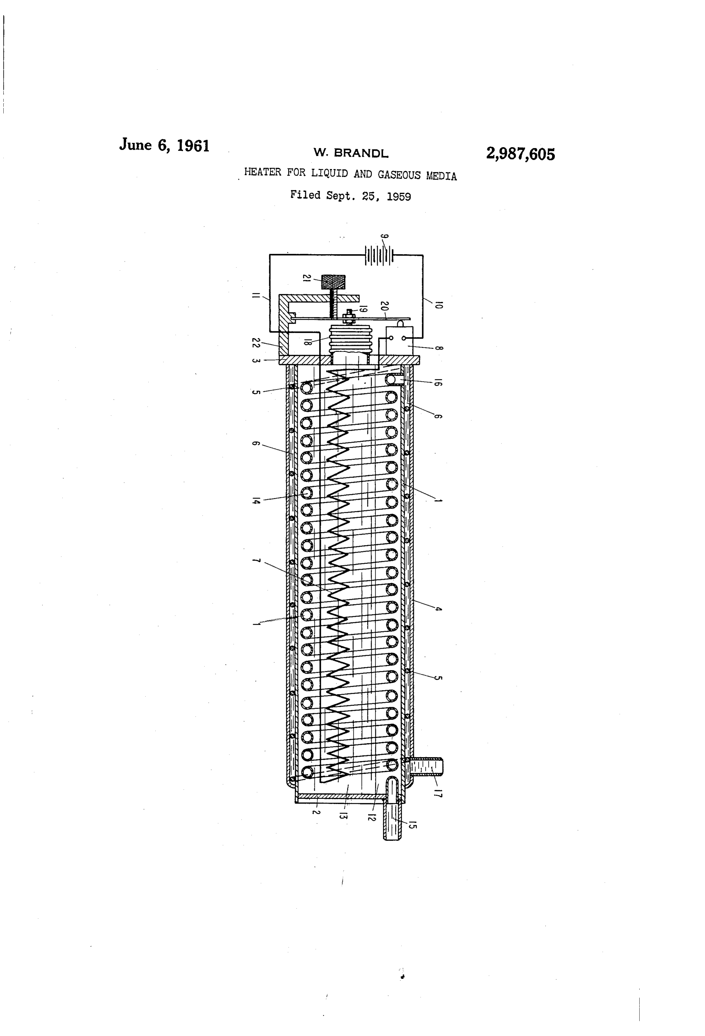
The present invention relates to a heater for liquid 7, the latter heats the water 13 which at once evaporates and gaseous media, particularly oils and more particularly in the evacuated space and heats the walls of the vessel. heavy fuel oils for the burners of heating plants. The temperature is a function of the pressure in the It is a principal object of the invention to provide a interior 12 of the vessel. This pressure causes a resilient heater of the kind referred to which permits a uniform expansion of the bellows 18. The latter bears through heating of the medium and prevents local over-heating the screw 19 on the leaf spring 20 and lifts the same off of a badly heat-conductive medium such as fuel oil and the switch 8 when its pre-stressing is overridden. There consequent coking thereof. These objects are of par by the heating current is interrupted, and is switched on ticular importance to heaters for the fuel oil of heating again only when the pressure has fallen below a pre plants where the output of the burners depends on the determined value, and accordingly at a predetermined viscosity and hence on the temperature of the fuel oil temperature. The pre-stressing of the spring 20 and supplied to the burners of the plant. accordingly the temperature of the heater can be adjusted With these and other objects in view which will become 20 by turning the screw 21.
apparent later from this specification and the accompany The oil to be heated is fed by a pump (not shown) ing drawing, I provide a heater for liquid and gaseous through the inlet socket 15 into the pipe coil 14 wherein media, comprising in combination: an evacuated vessel it is preheated. It leaves the latter through the port 16 having an outer shell and partly filled with a liquid, a and flows into the space between the shells. It flows source of heat arranged inside the said vessel, a control 25 through the latter between the baffles 5 on a helical path element responsive to the pressure prevailing within the until it reaches the outlet 17 and is passed to the oil said vessel mounted on the said vessel and operatively burner. The large heated surface of the shell 1 allows controlling the supply of energy to the said source of a quite uniform heating of the comparatively thin oil heat, a pipe line passing through said vessel through layer in the space 6 between the shells. Local overheat which the medium to be heated flows in operation for 30 ing of the oil which could lead to coking is prevented being preheated before being further heated on the said with safety by this design of the heater. outer shell of the vessel. Instead of the bellows 18 a simple resilient diaphragm Preferably the said shell is of double-walled construc could be used, and for the heating of the water 13 hot tion, the said medium, after being preheated, flowing gases or the like could be used instead of electricity. through the space between the double walls. Baffles are 35 While I have described herein and illustrated in the conveniently arranged between the double walls to posi accompanying drawing what may be considered a typical tively guide the flow of the medium to be heated. These and particularly useful embodiment of my said invention, baffles are conveniently made in the form of a wire heli wish it to be understood that I do not limit myself to cally wound in the said space betwen the double walls. the particular details and dimensions described and il These and other features of my said invention will be 40 lustrated; for obvious modifications will occur to a person clearly understood from the following description of a skilled in the art.
preferred embodiment thereof given by way of example What I claim as my invention and desire to secure by with reference to the accompanying drawing, in which Letters Patent, is:
the single figure shows in longitudinal section a heater A continuous heating apparatus for flowing liquids, for the heavy fuel oil to be supplied to the oil burners 45 as oils, said apparatus comprising a double-walled, her of a central heating plant. metically sealed, evacuated vessel, a body of a liquid The heater consists of a vessel having a cylindrical which evaporates when heated partly filling said vessel, shell 1, the end faces of which are closed in a gas-tight an electric heating element within said vessel for heating manner by bottoms 2 and 3. Around the shell 1 a second 50 said liquid, a switch for closing the circuit through said shell 4 is arranged at a spacing, and in the intervening heating element, a control unit subject to the pressure space 6 a helically wound wire 9 is inserted as a baffle. within said vessel for opening said switch at a predeter The interior 12 of the vessel is evacuated and partly filled mined pressure within said vessel, and means for adjust with water 13. In the interior an electrical heating ele ing said control means for operation at a desired pres ment 7 is arranged which is connected to a source of 55 sure within said vessel, in combination with a spiral current through a switch 8 and leads 10 and 11. More pipe within said vessel for contact with the heated evapo over the interior contains a pipe coil 14, which is in com rated liquid therein, an intake fitting in a wall of said munication with a supply line 15 passing through the vessel connected to one end of said spiral tube, for flow bottom 2 and with a discharge port 16 issuing into the ing liquid to be heated in the apparatus, a connection space 6 between the shells of the casing. In the outer 60 for the opposite end of said spiral pipe extending through shell 4 there is moreover arranged a discharge socket the inner wall of said vessel into the space between the 17, which communicates with the space 6 between the double walls thereof, and an outlet fitting extending shells.
through the outer wall of said vessel for flow of the
On the bottom 3 a temperature control device (known heated liquid out of the apparatus, whereby liquid to be in itself) is mounted which is illustrated diagrammatically 65 heated flows through the spiral pipe within said vessel only, since it does not form part of the invention as and is heated by the heated evaporated liquid in said such. It comprises a resilient bellows 18 the interior of vessel, flows from said pipe into the space between the which is in communication with the interior of the heater double walls of said vessel to be further heated and flows vessel. The bellows 18 acts through a screw 19 on a leaf 70 thence through said outlet fitting out of the apparatus, spring 20, which at one end is clamped in a holder 22 said Switch and said control unit maintaining the tem 3 perature within said vessel at a predetermined value set 1951,403 Goddard –––––––––––––– Mar. 20, 1934 by said adjusting means. 2,868,178 Peters ---------------- Jan. 13, 1959 References (Cited in the file of this patent FOREIGN PATENTS
UNITED STATES PATENTS 5 727,225 Great Britain ? ?????????????? Mar. 30, 1950
Provenance
- Collection
- Patents citing this work
- Pages
- 3
- Method
- pdftotext (the PDF's own text layer) + pdftoppm 300dpi page scans
- Patent office record
- patents.google.com →
- Source
- Google Patents citing-documents table
- Assignee
- Brandl Wilhelm
- Published
- 1961-06-06
- Transcribed from
- patentimages.storage.googleapis.com →