

patent · US3018764A
Marine boiler exhibiting small variations of level
30 January 1962
Text
Drawings
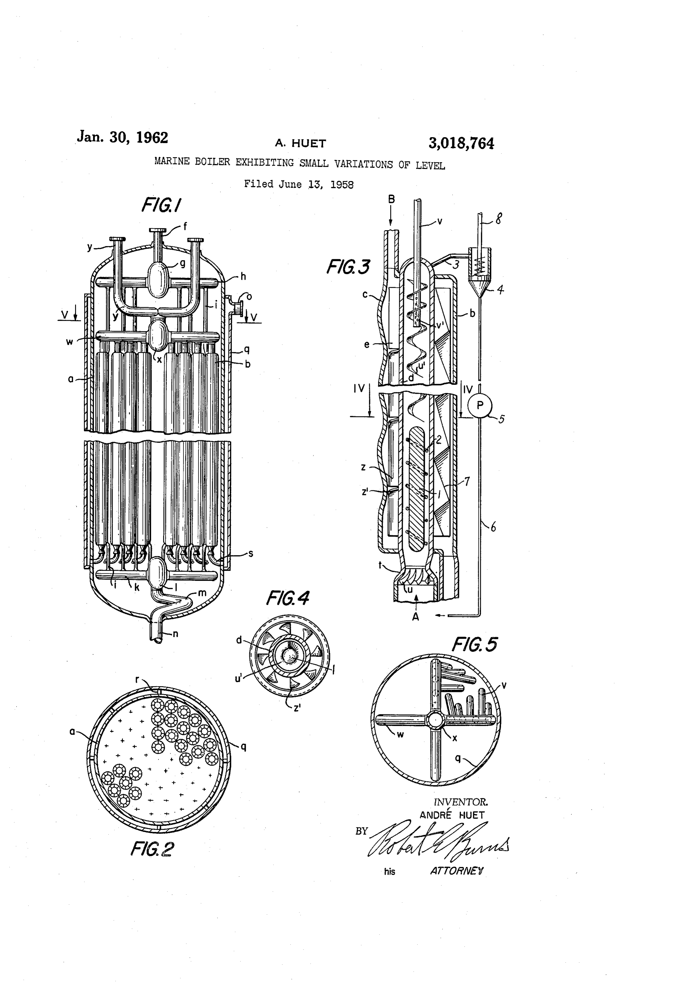
FIG. 1 is a view in elevation of a unit of the boiler. FIG. 2 is a cross-section through the median portion II of the boiler.
Page 1drawing sheetscan →
Page 2scan →
Marne boiler exhišthing small vara
André Huet, 48 Ave. du President Wilson, Paris, France
Claims priority, application France June 27, 1957
The present invention has for its object a marine boiler specially designed so that the water levels which are estab O lished in the different parts of the boiler are of rather lim ited area, so that when there are changes in the list of the ship, which may reach 40° and more, the inclination re Sulting therefrom in these levels cannot produce any inter ference with the efficiency and reliability of operation of 15 the boiler.
To this end, the evaporating portion of the boiler is sub divided into a large number of identical elements con stituted by double-circuit heat-exchanging tubes fed by the heating fluid and by the water to be vaporized, which 20 exchange their heat in these tubes, the variations of level which are produced inside the tubes for the water to be vaporized therefore affecting only a relatively small area by reason of the large number of these tubes.
Partitioning inside the jacket serving as an economizer for the preliminary heating of the water to be vaporized 25 likewise enables the water levels which may be established inside the economizer to be subdivided.
Other details of the boiler forming the object of the in vention will appear in the course of the following descrip 30 tion given with reference to the drawings, which are given by way of example.
FIG. 1 is a view in elevation of a unit of the boiler. FIG. 2 is a cross-section through the median portion II of the boiler.
FIG. 3 is a longitudinal section of one of the double 35 circuit heat-exchanging tubes provided inside the unit, FIG. 4 is a section on the line IV. IV of FIG. 3. FIG. 5 is a section on the line V V of FIG. 1 show ing the sub-headers of the heat-exchanging tubes. The boiler is constituted by a certain number of ident ical units, such as the one shown in FIG. 1. Each of these units comprises an outer shell a, which is preferably cylin drical and has a vertical axis, containing a large number of double-circuit heat-exchanging tubes which form the evaporating portion of the boiler. The number of these tubes inside the shell a in the example shown is about sixty and they have a length adapted to the power of the boiler. A heat-insulating material, such as glass wool or some other material, is packed between them to reduce the in 50 ternal air currents circulating between the tubes. Each of the latter is constituted, as shown in section in FIG. 3, by an outer tube b, the wall of which may be smooth or comprise corrugations c, as shown in the left-hand part of FIG. 3, and into which there is inserted a tube d carrying 55 external fins e. There is thus produced a double circuit heat-exchanging tube through which the water to be vaporized flows from bottom to top in the direction of the arrow A, while the heating fluid flows therethrough from top to bottom in the direction of the arrow B and circu 60 lates in the space contained between the two tubes b and d.
The heating fluid B may either be water under high pressure, or a gas, or a liquid metal. The fluid enters each unit a through the inlet pipe f supplving a feeder head g 65 at the top, into which feeder head there are inserted in the form of a cross four subheaders, such as shown at h, from which there depart the tubes such as shown at i, feeding each tube b of the evaporator at the top. At the bottom of the tubes h, the tubes j are connected 70 in similar manner to sub-headers k arranged in the form of a cross and terminating at a feeder headl from which
Patented Jan. 30, 1962 the outlet pipe m for the hot fluid departs, the outlet pipe leaving the shell a at n after making a turn permitting expansion.
The water is admitted into the shell a through the con nection o, which feeds a double jacket q surrounding the shell a externally, and the space between the jacket q and the shell a, which space is preferably partitioned at r, con stitutes a heat insulation and, if necessary a first econo mizer heating the feed water. The annular space between the jacket q and the shell a is connected at the bottom by tubess to the bottom part of the evaporating tubes d. In said bottom part of the tubes d there are provided slightly constricted inlet orifices t having helical ribs u, the effect of which is to give the water entering in the direction of the arrows A a gyratory movement. The constriction has the effect of injecting the water under pressure irrespec tive of the angular position which may be adopted by the device as a result of the rocking of the ship.
The lower part of each tube d is provided internally with a core comprising helical rib devices 2 and the as sembly formed by this lower part of the tube di functions as an economizer for first heating the water entering the tube and bringing it to the desired temperature. Follow ing this first part of the tube functioning as an economizer there is the part of the tube functioning as an evaporator. In this evaporating portion of the tube d there are pro vided surfaces devices ui in the form of a spiral, the pitch of which preferably continually decreases in the ascend ing direction of the tube d and the effect of which is to im part a gyratory movement to the rising mass of water and steam. Owing to this movement, the water is conveyed along the inner wall of the tube d, while the steam pro duced rises along the axis of the tube where the helical deflecting surfaces come to an end, before being released at the top of the tube d. The gyratory movement like wise stabilizes the water level inside the tube. In this up per part, the steam-evacuating pipe y penetrates somewhat deeply into the tube d and its end is perforated like a Sprinkler or has slots vi, as can be seen in FIG. 3, so as to form a device acting as a water and steam separator. Each of the pipes v is connected to sub-headers warranged in the form of a cross and terminating at a central feeder head x, from which the steam leaves through the double pipe y, which describes a turn facilitating expansion, be fore leaving the shell a and being conducted to the place of use.
At the top, for example, of each exchanger tube d there is also provided a device enabling any water not yet vapor ized to be absorbed, the water being conveyed through a pipe 3 to a water and steam separator 4 common to all the tubes of a unit a, for example.
Any water which may be delivered by the pump 5 to the pipe 6 rejoins the water being fed to the shell a, while any steam which may be separated in the separator 4 re joins the steam outlet circuity through the pipe 8. - The steam leaving the circuits y of all the units a may also pass through a supplementary general water and steam separator formed by a dome of known type (not shown)
Moreover, it is also possible to make the steam pass through a superheater (not shown).
It will be seen that with the arrangement adopted no clearly defined water level is established inside the tubes d and that, furthermore, if such a level is established, the listing of the ship producing an inclination in these levels affects an area of water which is so small that the func tioning of the vaporizing tube is not thereby impeded. Likewise, the partitions r which are provided between the jacket q and the shell a have the effect of dividing the water space acting as a heat insulation into com partments and, when changes are produced in the list of 3 the ship, the resultant inclinations in the level are lim outer tube at its upper end, to circulate through said an ited to each of the compartments provided between the nular space between the two coaxial tubes and to leave partitions r and consequently affect only a limited area of said outer tube at its lower end, means providing helical Water, so that the effect of the inclination is limited surfaces interiorly of the inner tube to impart a gyratory equally. movement to the mixture of water and steam contained In the Space comprised between the tubes b and d, the in the inner tube, and steam outlet means in the upper fins e of the tube d may be slit at z and turned down, as portion of said inner tube, headers to admit the heating can be seen at z (FIG. 4), so that the hot fluid, cir fluid to the inlet at the top of each of the outer tubes, culating in the space between the two tubes b and d di headers to collect the heating fluid at the bottom of the vided into compartments by the fins e, passes from time O outer tubes, tubes to admit water to the inlet at the bot to time from the space between two adjacent fins e to tom of each of the inner tubes, said steam outlet means the neighboring space, which ensures a powerful sweep comprising a separator of steam and water at the top ing action on the fins and on the outer surface of the of each inner tube, a tube to collect the water from the tube d, thus securing a better exchange of heat. separator, a second separator common to all the coaxial When a tube b exhibiting changes of cross-section, as 15 heat exchanging tubes, said last-named tube leading to shown at c on the left in FIG. 3, is used, these changes said second separator, a tube to recirculate the water sep of cross-section cause changes of direction, pressure and arated in said second separator, and a tube to collect the velocity in the flow of the hot fluid and these changes are steam separated in said second separator. favorable to the exchange of heat. It is possible to sub 3. A marine boiler as defined in claim 1, wherein said stitute for these corrugations c a tube b which is com 20 separator of steam and water comprises a steam discharge pletely smooth externally and to arrange inside the space tube extending coaxially into each inner tube, said steam contained between the tubes b and d corrugated strips 7 discharge tube being formed with a plurality of apertures extending between the fins e and which have the effect for receiving the steam.
of producing in the same way changes of cross-section 4. A marine boiler as defined in claim 2, wherein said in the spaces offered to the flow of the hot fluid. 25 separator of steam and water comprises a steam discharge It is obvious that modifications of detail may be made tube extending coaxially into each inner tube, said steam in the embodiment of this invention without thereby de discharge tube being formed with a plurality of aper parting from the scope thereof. tures for receiving the steam.
What I claim is: 5. A marine boiler effective to undergo only small 1. A marine boiler effective to undergo only small 30 variations of water level in response to movements of variations of water level in response to movements of the ship in which it is mounted comprising, in combina the ship in which it is mounted comprising, in combina tion, a shell, a plurality of vertical double-circuit heat tion, a shell, a plurality of vertical double-circuit heat exchanging tubes disposed in said shell and adapted to be exchanging tubes disposed in said shell and adapted to be fed by the heating fluid and by the water to be vapor fed by the heating fluid and by the water to be vaporized, 35 ized, each heat-exchanging tube comprising a single uni each heat-exchanging tube comprising a single unidirec directional inner tube and an outer coaxial tube defining tional inner tube and an outer coaxial tube defining an an annular space between them providing a flow passage annular space between them providing a flow passage for the heating fluid, the inner tube being formed with an for the heating fluid, the inner tube being formed with inlet at its lower end to receive the water to be vaporized an inlet at its lower end to receive the water to be vapor 40 and the outer tube being formed with an inlet at its ized and the outer tube being formed with an inlet at upper end to receive the heating fluid and an outlet at its its upper end to receive the heating fluid and an outlet lower end for evacuation of said heating fluid, said heat at its lower end for evacuation of said heating fluid, said ing fluid thereby being adapted to enter said outer tube heating fluid thereby being adapted to enter said outer at its upper end, to circulate through said annular space tube at its upper end, to circulate through said annular 45 between the two coaxial tubes and to leave said outer space between the two coaxial tubes and to leave said tube at its lower end, means providing helical surfaces outer tube at its lower end, means providing helical sur interiorly of the inner tube to impart a gyratory move faces interiorly of the inner tube to impart a gyratory ment to the mixture of water and steam contained in the movement to the mixture of water and steam contained inner tube, and steam outlet means in the upper por in the inner tube, and steam outlet means in the upper 50 tion of said inner tube for withdrawing steam directly portion of said inner tube for withdrawing steam directly from the upper portion of said inner tube, said steam from the upper portion of said inner tube, headers to ad outlet means comprising a steam discharge tube extend mit the heating fluid to the inlet at the top of each of the ing coaxially into each inner tube, said steam discharge outer tubes, headers to collect the heating fluid at the bot tube being formed with a plurality of apertures for re tom of the outer tubes, tubes to admit water to the inlet 55 ceiving the steam.
at the bottom of each of the inner tubes, said steam out 6. A marine boiler effective to undergo only Small let means comprising a separator of steam and water at variations of water level in response to movements of the top of each inner tube, means to recirculate the sep the ship in which it is mounted comprising, in combina arated water, and headers to collect the steam from said tion, a shell, a plurality of vertical double-circuit heat steam outlet means. 60 exchanging tubes disposed in said shell and adapted to be 2. A marine boiler effective to undergo only small varia fed by the heating fluid and by the water to be vapor tions of water level in response to movements of the ized, each heat-exchanging tube comprising a single uni ship in which it is mounted comprising, in combination, directional inner tube and an outer coaxial tube defining a shell, a plurality of vertical double-circuit heat-ex an annular space between them providing a flow passage changing tubes disposed in said shell and adapted to be 65 for the heating fluid, the inner tube being formed with fed by the heating fluid and by the water to be vapor an inlet at its lower end to receive the water to be vapor ized, each heat-exchanging tube comprising a single uni ized and the outer tube being formed with an inlet at its directional inner tube and an outer coaxial tube defin upper end to receive the heating fluid and an outlet at its ing an annular space between them providing a flow lower end for evacuation of said heating fluid, said heat passage for the heating fluid, the inner tube being formed 70 ing fluid thereby being adapted to enter said outer tube with an inlet at its lower end to receive the water to be at its upper end, to circulate through said annular space vaporized and the outer tube being formed with an in between the two coaxial tubes and to leave said outer let at its upper end to receive the heating fluid and an tube at its lower end, means providing helical surfaces interiorly of the inner tube to impart a gyratory move outlet at its lower end for evacuation of said heating fluid, said heating fluid thereby being adapted to enter said 75 ment to the mixture of water and steam contained in the 4 inner tube, and steam outlet means in the upper portion 1948,541 of said inner tube for withdrawing steam directly from 2,220,944 the upper portion of said inner tube, and means defining 2,240,100 corrugations on the surface of the outer tube, said sep 2,291,195 arator of steam and water comprising a steam discharge 2,379,661 tube extending coaxially into each inner tube, said steam 2,587,530 discharge tube being formed with a plurality of apertures 2,779,724 for receiving the steam. 2,796,050 References Cited in the file of this patent 0.
United states patents 727,225
1951,403 Goddard -------------- Mar. 20, 1934 921,339
Foreign patents
Provenance
- Collection
- Patents citing this work
- Pages
- 4
- Method
- pdftotext (the PDF's own text layer) + pdftoppm 300dpi page scans
- Patent office record
- patents.google.com →
- Source
- Google Patents citing-documents table
- Assignee
- Huet Andre
- Published
- 1962-01-30
- Transcribed from
- patentimages.storage.googleapis.com →