

patent · US3161228A
Method of gasifying liquid fuels
15 December 1964
Text
Drawings
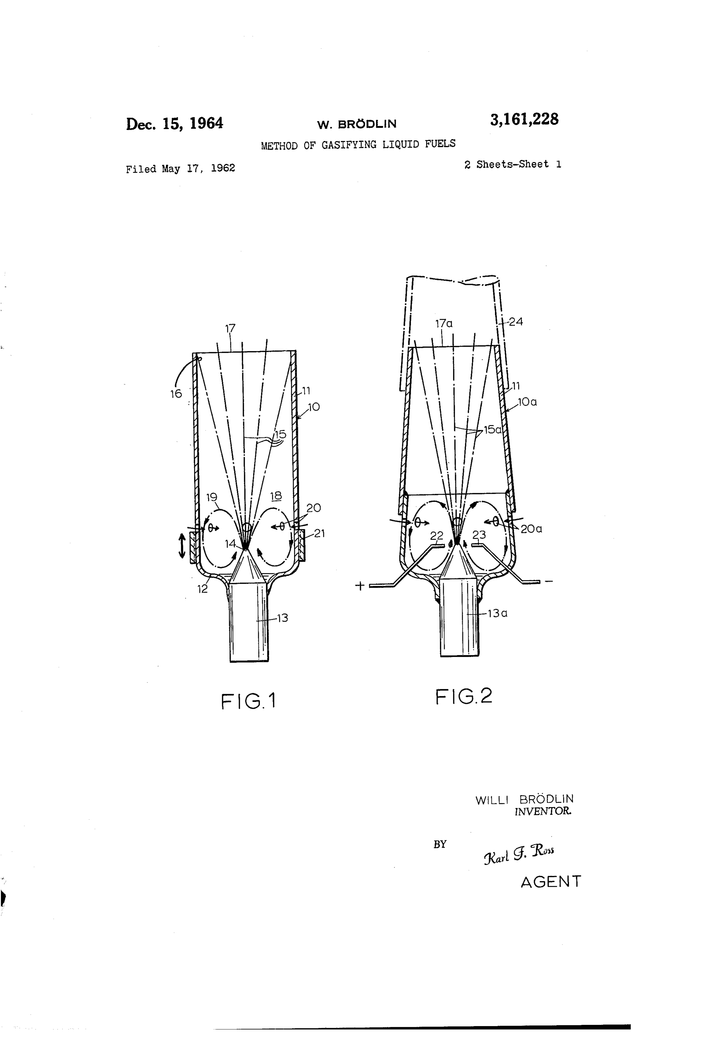
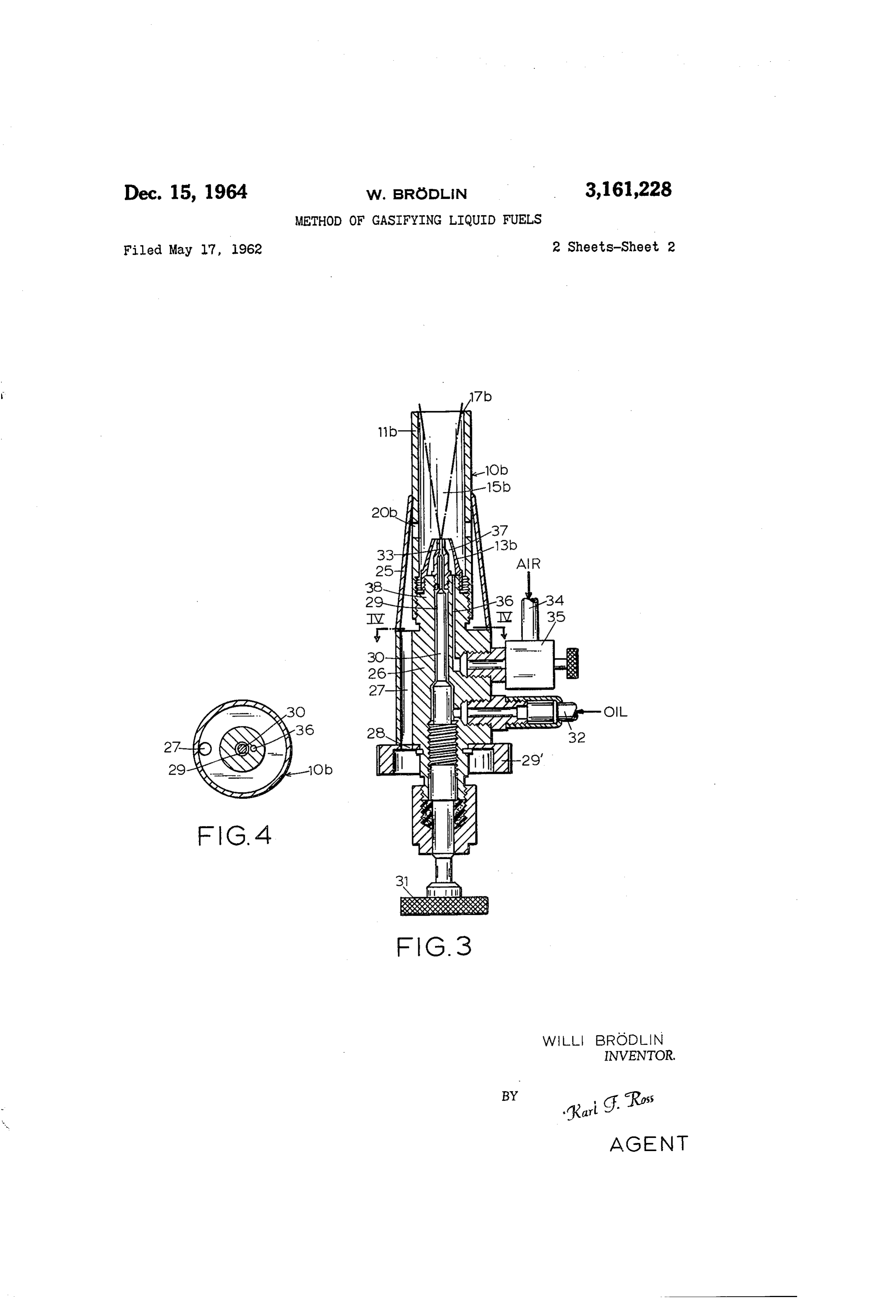
FiG. 1 shows, in axial section, a gasifying device em bodying the invention;
FIG. 2 is a view similar to FIG. 1, showing a modi fication;
Page 1drawing sheetscan →
Page 2drawing sheetscan →
Page 3scan →
Methosd of gasefying lassjaa fuels
Wii Brödia, Aiiesiach a Boersee, Gergaaaay
Clairs priority, application (Geria y Tyay 7, 96, 5
My present invention relates to a method of gasify ing liquid fuels, especially hydrocarbons such as oil, and to a device for carrying the method into practice. O An object of this invention is to provide a method of carrying out such gasification in a manner resulting in a readily combustible gas capable of being burned with a blue, relatively soot-free flame either in situ or at some other location to which the gas may be subsequently 5 conveyed.
Various proposals are known for increasing the effi ciency of burners utilizing a fuel oil. Thus, it has been found desirable to recirculate the combustion products of an inner flame, maintained within a burner tube, by 20 means of bypass channels carrying the hot gases pref erably in a burning state back to the origin of that fame at the aperture of a nozzle into the tube. This has been more fully disclosed in my copending applica tion Ser. No. 834,245, filed August 17, 1959 and now abandoned, which described a variety of structures for creating such bypass channels and of which the pres ent application is a continuation-in-part. These chan nels, however, must evidently be made of a highly re fractory material to withstand the heat of the recircu lated gases, it being therefore a more particular object of my present invention to provide an improved type of gasifying device, adapted to be used as a burner or as a gas generator, in which the need for such chan 35 neis has been obviated.
in my aforementioned copending application I have already indicated, with particular reference to FIG. 4 thereof, that it is possible to create in a burner cham ber a combustion-promoting turbulence through the in troduction of a gas stream into the chamber. This aero 40 dynamic creation of turbulence is the principle of my present invention and involves the injection of a high speed stream of oxidizing gas such as air, along with a flow of liquid fuel to be atomized thereby, into a burner tube so as to produce a substantially conical spray 45 which preferably contacts the wall of the tube near its mouth and leaves around the aperture of the injection nozzle a generally toroidal pocket in which a vortex is generated by the pressure difference existing along the 50 tube. In contradistinction to prior proposals have found it essential that the air/fuel mixture circulating in this vortex contain an undersupply of air, i.e. a quan tity of oxygen considerably less than the stoichiometric amount required for the combustion of the fuel. Thus, there occurs in the region of the nozzle outlet a pre liminary combustion which is only partial and which serves to decompose the hydrocarbons of the mixture into readily burnable components such as hydrogen and carbon monoxide. Naturally, the same conditions are 60 realizable if pure oxygen instead of air is admitted into the tube along with the fuel stream.
In general, the understoichiometric amount of oxygen may be supplied to the precombustion Zone near the nozzle outlet in a variety of ways. This includes the 65 feeding of the oxygen (alone or as part of an air flow) to the nozzle as an atomizing fluid for the injected fuel and therefore in the same direction as the latter, the admission of supplemental air through lateral ports in cross-flow to the ignitable mixture, and/or the aspira O tion of atmospheric air through the burier mouth in counterflow to the fuel stream. Particularly the air in
Patented Dec. 15, 1964 take from this latter source can be readily limited or completely shut off by near or actual contact of the base of the spray cone with the tube wall. The angle of divergence of this cone, i.e. the angle included be tween its generatrices and its axis, will normally run between 10° and 30.
in most instances it will be advantageous to deliver the fuel at relatively low pressure to the nozzle aper ture and to atomize it by an accompanying air or oxy gen stream of high velocity, preferably ranging from at least 50 m./sec. to or beyond 500 m/sec., whose gauge ressure may lie between 0.5 and 5 atmospheres. The oxygen content of the atomizing air will normally be in the vicinity of 5% of the stoichiometric amount so that further oxygen, e.g. from secondary air, will be needed to sustain the partial combustion within the tube. The total oxygen content of the atmosphere in the tube falls short by, preferably, about 30% of the stoichiometric quantity as set forth in my copending application Ser.
The invention will be described hereafter with greater detail, reference being made to the accompanying draw ing in which:
FiG. 1 shows, in axial section, a gasifying device em bodying the invention;
FIG. 2 is a view similar to FIG. 1, showing a modi fication;
F.G. 3 illustrates, also in axial sectional view, a fur ther embodiment; and
F.G. 4 is a cross-sectional view taken on the line
The burner 10 illustrated in F.G. 1 comprises a tube is here shown to be metallic although it is also possible, in this and other embodiments, to use a ceramic tube clad with a refractory metallic sheath as particularly shown in FIG. 5. Tube contracts at its upstream end 2 to hug a nozzle 3 whose outlet 14 emits an ignitable mixture in a conical spray 5 having an angle of divergence c. of about 10%. It will be noted that the cone 15 contacts the inner wall of tube 11 at a loca tion 6 just ahead of the tube mouth 7. Between this location and the upstream end 52 there is defined by the inner tube wall, the nozzle 3 and the cone 35 a generally toroidal pocket i8 into which part of the injected aerosol mist is deviated in a toroidal vortex 29 due to the pressure difference between the high-pres sure region of expanding gases at the tube mouth 7 and the low-pressure region at the nozzle outlet 4. The vortex S9 is supplied with additional air through lateral ports 20 whose effective cross-section can be ad justed by means of a ring 25 axially slidable on the tube Af. The nozzle 13 may have a construction sim ilar to that described hereinafter with reference to FIG, 3. When the emergent spray is ignited at the tube mouth A7, the flame flashes back into the interior of the tube to set up combustion in the region of turbulence within pocket 8 whereby the vortex 19 turns into a flame. Alternately, particularly if the gaseous output of the device is to be connected to a different location for stor age or utilization, such an internal flame can be pro daced by the use of igniter electrodes 22, 23 as shown in FIG. 2 for a modified gasifier Ga. In the latter figure, wherein the shape of the spray cone 5a from nozzle E3a remains substantially unchanged, the sur rounding tube is shown composed of a frustoconical downstream section a welded onto a cup-shaped up stream section 52a provided with the ports 20a. The iniet area of these ports 22, as in the preceding embodi ment, can be regulated by suitable means not further
Though the device Oa shown in FIG. 2 may of 4 course be used as a burner in the same manner as the the spirit and scope of the invention as defined in the ap device () of FIG. 1, have schematically illustrated at pended claim.
24, a conduit for carrying off the gas produced at the claim: - . .. .
mouth. 7a of tube section 11a. - .. . . . A method of producing a combustible gas, comprising FIGS. 3 and 4 show a gasifier 10b, with a straight cylin 5 the steps of axially injecting into a generally cylindrical drical-discharge tube 11b, a nozzle 13b producing a spray chamber open at one end, adjacent a closed end of said cone 15b, a shell 25 forming an annular housing about chamber, an admixture of atomized liquid hydrocarbons the upstream portion of tube 11b which is provided with with a high-velocity stream of oxidizing gas with a veloc the ports 20b, and a central body forming a support for ity of substantially 50 to 500 meters per second and con the elements referred to. This body has a channel 27 O stituting on the order of 5% of the stoichiometric quan through which atmospheric air may be admitted into the tity of oxygen necessary for complete combustion of said annular clearance between body 26, and the shell 25 by ward hydrocarbons, thereby creating a spray cone diverging to way of an entrance opening 28 in a ring 29, rotation of said open end at an angle of substantially 10 to this ring thus enabling regulation of the air supply through 30, so positioning said cone within said chamber as to ports 26b by varying the alignment between channel 27 I5. provide a generally toroidal pocket around the apex of and opening 28. A central bore 29 in body 26 accom-- said cone communicating with the remainder of said modates a needle valve 30 whose axial position is adjust tion chamber over substantially its entire transverse cross-sec able by a knob 3 whereby the flow of fuel oil from a while allowing at most a small clearance between the supply pipe 32 through bore 29 into the central orifice 33 base of said cone and the inner chamber wall with conse of nozzle 13b. can be selectively throttled. Air under pres 20 quent generation of a vortex of ignitable mixture from sure, arriving through a pipe 34, flows through a similiar said spray cone within said pocket, igniting said mixture regulating valve 35 into a lateral passage 36 of body. 26. whereby a flame is established in said vortex, admitting terminating at an annular channel 37 of nozzle 13b sur 'additional oxygen to said pocket adjacent the apex of rounding its orifice 33. The resulting spray. 15b, strikes. said cone, and limiting the supply of oxygen in said cham the wall of tube b near its mouth 17b or passes out 25 ber to substantially less than the stoichiometric quantity wardly in close proximity thereto so as to create condi needed for combustion of said hydrocarbons whereby a tions of turbulence similar to those previously described. combustible gas issues from said open-end, said spray cone The region of impingement, if any, of the spray upon the blocking substantially completely the entrance of outside air into said chamber through said open end, said oxidiz tube wall is adjustable as the tube 11b, rotatable within :30 ing its sleeve 25, is threadedly secured to a boss 38 of body gas being admitting into said chamber at a gauge pres 26 so as to be displaceable relatively thereto in axial sure ranging between substantially 0.5 and 5 atmospheres - direction. and providing with said additional oxygen an oxygen sup The gasifiers according to the invention operate in all ply in said chamber limited to approximately 70% of instances substantially free from soot and without traces 3 5 said stoichiometric quantity.
of glowing particles in the outer or secondary-stage flame References Cited in the file of this patent produced thereby. This flame springs up immediately . . UNITED STATES PATENTS after ignition, in the cold state of the burner, and can be suitably regulated by the various adjustment means de 710,130 . Weiss---------------- Sept. 30, 1902 scribed in connection with FIGS. 1 and 3. The axial ex 945,967 Mahr ------------------Jan. 11, 1910 tent of the turbulence zone can be very limited, e.g. of 40 1,199,716 Severs ---------------- Sept. 26, 1916 the order of 20 mm., without interfering with the ready 1,373,190 ignitability of the inner or first-stage flame. In those 1,869,897. Hymer ----------------- Aug. 2, 1932 cases where the developing gas is carried off for combus 2,207,010. Hopkins---------------- July 9, 1940 tion elsewhere, e.g. as illustrated in FIG. 2, it will of 45 2,515,845 Van den Bussche -------- July 18, 1950 course be necessary to supplement it with additional air 2,675,993 Smith et al. ------------ Apr. 20, 1954 or oxygen at the combustion site to establish the stoichi 2,701,608 Johnson ----------------- iFeb. 8, 1955
Modifications of the specific structures described and FOREIGN PATENTS illustrated are, of course, possible without departure from 50 5,715 Great Britain ---------------- of 1886
Provenance
- Collection
- Patents citing this work
- Pages
- 4
- Method
- pdftotext (the PDF's own text layer) + pdftoppm 300dpi page scans
- Patent office record
- patents.google.com →
- Source
- Google Patents citing-documents table
- Assignee
- Brodlin Willi
- Published
- 1964-12-15
- Transcribed from
- patentimages.storage.googleapis.com →