

patent · US3171469A
Direct ignition for fuel burners
2 March 1965
Text
Drawings
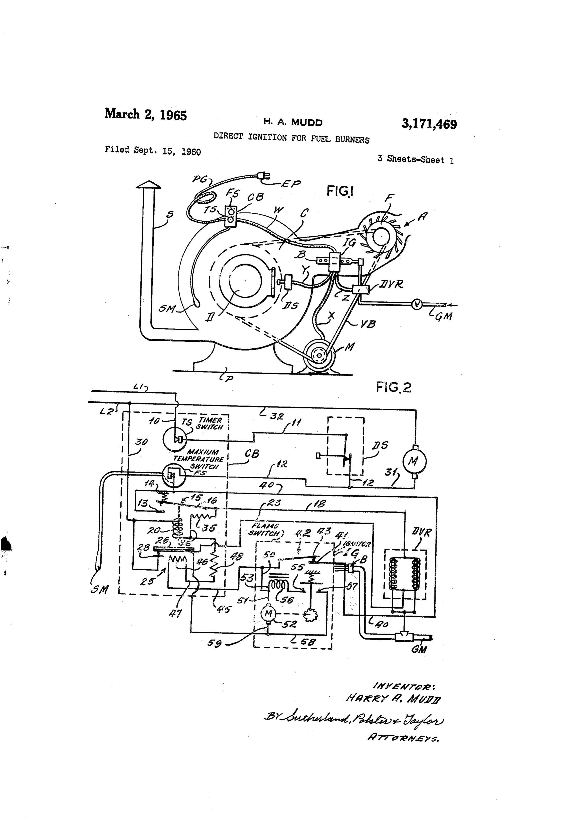
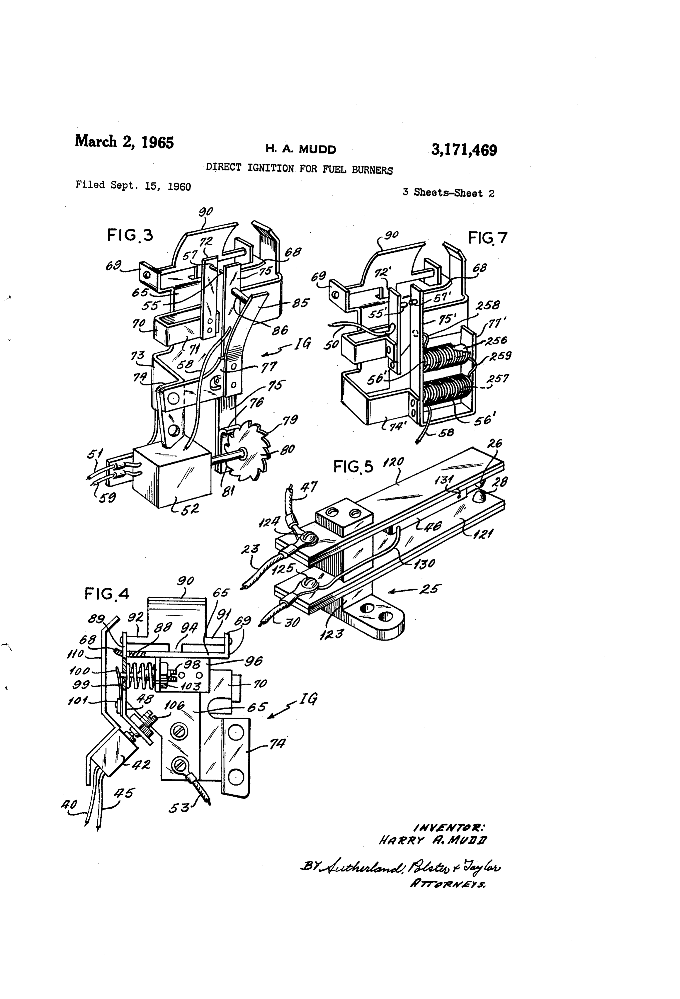
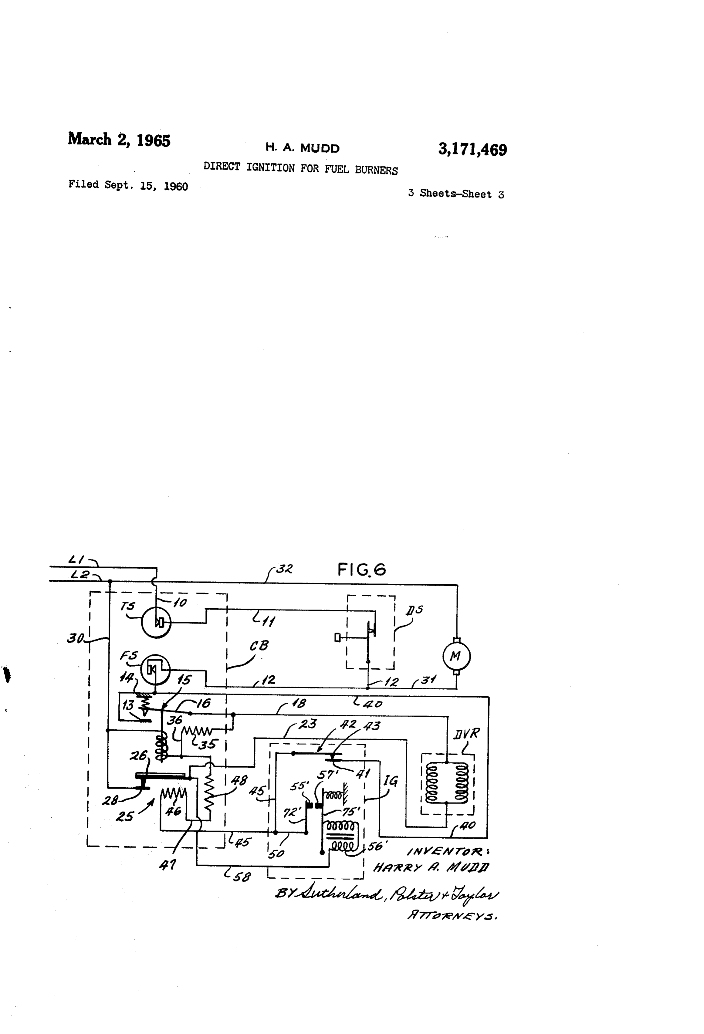
FIG. 6 illustrates the circuit shown in FIG. 2 modified closing to connect thereto the ignitor shown in FIG. 7. As will said points relatively rapidly actuated by said be readily recognized, the substitution of the ignitor 55 electric motor.
Page 1drawing sheetscan →
Page 2drawing sheetscan →
Page 3drawing sheetscan →
Page 4scan →
United States Patent Office 3,171,469 Patented Mar. 2, 1965
3,171,469 According to this invention, the fuel supply for a DIRECT FIGNITION FORFUEL BURNERS main fuel burner is controlled by a circuit which includes Harry A. Midd, Clayton, Mo., assignor to McQuay-Norris a starting circuit for the ignition cycle connected to an Manufact of Delaware ring Company, St. Louis, Mo., a corporation ignitor circuit energizing make and break electric con tacts generating the ignition spark to ignite the main
Filed Sept. 15, 1960, Ser. No. 56,284 fuel burner after operation of the main fuel burner valve. 10 Claims. (CI. 158-125) Ignition of the main burner in turn disables the ignitor This invention relates to direct ignition for fuel burners circuit. The invention also includes a timer switch for and more specifically to an electric control system in the starting circuit in case the main burner does not cluding an electric ignitor of the make and break type 10 light, control which timer switch temporarily de-energizes the circuit. The power actuation of the make and which is adapted for connection to, and direct ignition break contacts may be electrical or pneumatic, both kinds of, a main gas burner for various kinds of gas fired ap wiil be hereinafter described. The contacts themselves pliances. This invention eliminates the need for a so called pilot light or pilot burner and the safety systems have been found to be extremely durable when con associated there with. The direct ignition, hereinafter it 5 Structed of a suitable alloy such as one of tungsten and lustrated, is described as it is adapted to the use in clothes thorium. When the current is limited to between 4 driers for home use, but as this description proceeds it and 1 ampere at 115 volts, contact life is measured in will become apparent to those skilled in the art that millions of cycles.
this direct ignition is applicable to gas fired heaters, gas 20 tionThein following is a detailed description of the inven Such full, clear, and exact terms as to enable fired incinerators and other gas appliances using gas fired any person skilled in the art to make and use the same burners which must be operated intermittently rather when taken with the illustrations in the accompanying than continuously. In other words, direct ignition is a drawings in which:
Substitute for a gas pilot light or the like.
Most clothes driers for domestic use operate on the cally FiG. 1 is an environmental view illustrating schemati same principle. The clothes to be dried are placed in 25 drier the general arrangement of machine elements of a a closed chamber in which they are agitated, and are machine;
subject to a circulation of air to absorb the water from FIG. 2 is a wiring diagram of the control circuit for the clothes. Usually a fresh continuous supply of air is theFIG.
drier illustrated in FIG. 1;
heated by a gas burner and then circulated by force 30 a Switch3mechanism is a perspective view schematically illustrating for direct ignition of a fuel burner;
through the chamber in which the clothes are being FIG. 4 is a view similar to FIG. 3 illustrating the agitated. Ordinarily, drying machines are equipped with reverse side of the mechanism;
controls for limiting the duration of the cycle and the FIG. 5 is a perspective view schematically illustrating maximum temperature attained in the drying chamber. an electrically heated thermostatic switch, termed a warp The timing switch or timer determines the duration of the drying period while the maximum temperature limit 35 switch, for controlling the cycling of the ignition; FIG. 6 is a wiring diagram of a modified form of the
Switch turns off the gas burner when the temperature invention; and in the drying chamber reaches a preset maximum during FIG. 7 is a perspective view of an ignitor employed in the circulation of air in the chamber. When the cham ber temperature has fallen to a predetermined lower the embodiment illustrated in FIG. 6. value, the maximum temperature limit switch conditions 40 of FIG. 1 shows a schematic arrangement of the elements a drying machine so arranged as to facilitate an un the control system to relight the gas burner. Conse quently, during a drying cycle determined by the timer derstanding of this invention. The arrangement shown herein is not the usual commercial construction and is switch, the gas burner is turned off and on repeatedly. intended to be illustrative only. According to FIG. 1, Obviously, such a system would be incomplete without 65 a drying chamber C in the form of a cylindrical housing some means for relighting the gas burner. Heretofore, a gas pilot light or burner was provided for this pur isdoor mounted on a pedestal P and provided with a round D for access to the chamber C. Within the cham pose, and the control system for the burner included also a control system for the pilot burner so interlocked ber C is an agitator for moving the clothes around in the in the control system that unless the pilot burner was 50 chamber C during the drying operation to permit exposure operating the main burner control valves remain closed. of the surfaces of the clothes to the drying current of Thus, such systems were complicated by providing an air. Air is supplied from the inlet A to the chamber C ignitor for the pilot burner connected with a solenoid by a blower F, and the air from the blower F passes over for the pilot burner valve which were operated simultane a burner B on its way to the chamber C. The addition ously, together with a flame switch heated by the pilot 55 of heat from the burner B to the current of air from burner which could disable the ignitor and condition the the blower F raises the temperature of the air and there control system for the operation of the main burner by decreases its relative humidity. This warm current of control valve. Prior systems for direct ignition of the air picks up moisture from the clothes within the cham main burner are also known in which the ignitor is a ber C and then discharges from the chamber C by way sparking plug operating at about 4000 volts input. 60 of the stack S, preferably to outside atmosphere. The It is one of the objects of this invention to eliminate agitator within the chamber C and the blower F are driven from burner control systems some of the complication from an electric motor M which has a suitable drive pulley necessary when a pilot burner is used. engaging the belt VB which in turn is trained over driven It is another object of this invention to eliminate the pulleys on the shaft of the blower F and on the agitator presence of higher voltage in such control systems in 65 shaft (not shown). The burner B is supplied with fuel which direct ignition is obtained by a sparking plug. from a gas main GM which connects with a solenoid It is a further object of the invention to improve the operated dual valve and regulator DVR located in a suit dependability of systems for direct ignition of main fuel able housing. The dual valve and regulator DVR can burners. be of conventional construction well known in the art, It is still a further object of the invention to obtain a O and is so located in the gas main GM as to control the system for direct ignition of main fuel burners which flow of gas to the burner B. It is therefore one of the will fail safe. control elements. Adjacent the burner B is another 5 control element, the ignitor iG, which will be described through the conduits W, X, Y and Z to the various con more in detail hereinafter. Adjacent the door D is a door trol elements to which they are connected, respectively. switch DS which is opened when the door is opened and The burner circuit also includes a holding circuit, which has a resistor 35 connected with the lead 18 and by a lead closed when the door D is closed. This switch is installed .
in the system as a safety device. Shown on the top of 36 extending to the opposite end of the solenoid coil 20, the chamber C is a control box, CB. Within the box CB heretofore mentioned. The holding circuit maintains the relays 15 closed after the burner circuit. has been once are the control elements, mechanisms and control circuits. energized which are connected with the ignitor IG, the dual valve by operation of the starting circuit. and regulator DVR, motor M and door switch.DS by The starting circuit has a lead 40 extending from switch interconnecting conduits W, X, Y and Z which enclose. O FS by connection with lead 14. The starting circuit re the wiring harness forming the necessary circuits for op mains open until all of the switches TS, DS and FS are eration of each of these control elements from the control closed. Lead 40 extends to fixed terminal 41 of the flame circuit within the box CB. These circuits are in turn con switch, generally indicated as 42. The movable contact 43 of this switch is connected by a lead 45 with a re nected with house current of 115 volts by the portable cord PC and the electric plug EP. Also connected with 15 sistance heater 46 on the warp switch 25, and resistance the control box CB is a temperature sensing means SM heater 46 is connected by a lead 47 in series with a re sistor 48 to the solenoid 20 and with lead 30 to input which extends from the control box to within the cham ber C. The above description will suffice as background line L2.
for an understanding of the invention which pertains to The ignitor circuit has a lead 50 connected with the direct ignition of the fuel burner B by the ignitor IG and 20 starting circuit between the flame switch 42 and the timer to the control system within the control box CB which ingiG. switch 25 which connects to the ignitor within the hous is connected thereto and with the other elements of a Lead 50 has two branches, one of which 51 con control, such as door switch DS, dual valve and regulator nects with one terminal of a motor 52 and the other of DVR and motor M. which 53 connects with one of the make and break con Attention is now directed to FIG. 2, which illustrates 25 tacts 55 through an inductance 56 which limits the cur schematically the wiring diagram and control mechanism . rent flow to the contact 55 to /2 to 1 ampere. Contact within the control box CB and its electrical interconnec 57 of the make and break ignitor is connected by a lead 58 to a lead 59 which extends from the motor 52 to the tion with the other control elements. With reference to this same figure, the control box CB contains two switches line 30 through the timer switch 25. As will hereinafter TS and FS. The switch TS is a settable clock switch with 30 be described, the motor 52 operates the make and break an externally exposed knob carrying an indicator and contacts. 55 and 57 into and out of contact so as to create operating over an indicator dial. By movement of the a spark for direct ignition of the burner B. ... . . . . exposed knob on the switch TS, the total time or dura I switch FIGS. 3 and 4 show two views of a combined flam tion of the drying cycle is set. Switch FS is operated by and ignitor switch suitable for the above system. sensing means SM and has an externally exposed knob 35 Acarriesmetal stamping 65 forms a support for this switch and at its upper end an offset ear portion 69 extending for setting the maximum drying temperature in the cham ber C. The switch mechanism. FS is so designed that it laterally from the support 65 in one direction and a opens not only at the temperature to which it is set by its lateral extending part 68 in the opposite direction. Be exposed control knob, but also whenever a fixed cali 40 tionlow the extension 69 is a U-shaped bracket having a por brated maximum temperature is exceeded. In FIG. 2, 71 overlying the support 65. Riveted to the overly the lines L1 and L2 represent schematically the power ing portion 71 is one leg 72 carrying one of the contacts input to the control box CB through the portable cord 57 of the make and break. Support 65 also has an off PC. These lines Li and L2 are connected with three dif set bracket 73 having a portion 74 spaced from the sup port portion 65 and in an offset plane with relation there ferent circuits and one subsidiary circuit within the control box CB, which will be described consecutively. 45 to. Bracket 73 has an insulated fiber support 77 riveted Line L1 connects to a lead 10 to the switch, heretofore thereto which carries on its lower side a leg 75 mounted mentioned, TS and to a line 11 which extends to one . . thereonto oscillate so that contact 55 carried thereby may terminal of the door switch DS. The other terminal of the be moved into and out of engagement with the contact 57 on the leg 72. Leg 75 has a cam follower 76 posi door switch DS is connected by a lead 12 with lead 31 to motor M and 32 from the motor M to the line L2, so 50 tioned to be engaged by the ratchet shaped teeth 79 that when switches TS and DS are closed motor M op on the fiber cam 80. Motor 52 drives shaft 81 carrying erates to drive the blower F and agitator. Line 12 also cam 80 preferably at a speed of about the distance be connects with switch FS in the burner circuit and by a tween ratchet teeth 79 in one second. The leaf spring lead 14 with a fixed terminal 13 of a relay 15. Relay 85 is riveted to the upper side of insulating member 77 15 is normally open and closed by energization of its 55 and has a projection 86 tending to force the contacts 55 solenoid 20. Movable contact 46 is connected by a and 57 together. The construction is such that when lead 18 with the solenoid operating mechanism of the motor 52 is operating, the contacts 55 and 57 are sepa dual valve and regulator DVR, shown schematically with rated rapidly by the action of the ratchet teeth 79 en in its own casing. This valve regulator is normally gaging the follower 76. Between teeth, spring 85 forces closed and opened for regulation of the gas flow only 60 the contacts back together. - when energized. A lead 23 extends from the opposite. Turning now to FIG. 4, the extension 68 is apertured end of the solenoid of the valve DVR to timer switch at 88 to receive a switch operating arm 89. Between the 25 which has a movable contact 26 normally closed with flameupper end of operating arm 89 and extension 69 is a a relatively stationary contact 28 of the warp switch 91 anddeflector 99 with a pair of laterally extending legs 92 wedged between the inner surface of the ex 25. Lead 30 connects the fixed contact 28 with input 65 line L2 to complete the burner circuit. Lines 31 and tension 69 and inner surface of the Switch operating 32 are connected respectively to leads 12 and 30 and arm 89. Legs 91 and 92 are supported in this position by pin extensions projecting through suitable apertures extend to the motor M. It will be noted that lead 31 is in series relation with the switches TS and DS, so that in the extension 69 and the switch operating arm 89. motor M is operating when these Switches are closed. 70 inFlame deflector 90 has a tongue 94 received in a groove the bracket 65 so as to maintain the deflector 90 in been shown as extending from the casing of housing CB position against rotation. It will be understood that the at different points, Actually this is merely an expedient tongue 94 has a loose fit in a slot in the bracket 65 so as to permit slight movement of the flame deflector 90.
to clarify the illustration, as it will be understood, that One leg of angular piece 96 is secured to the bracket 65 all of these leads extend from the control higusing CB
Page 6scan →
S 6 by suitable rivets, and the other leg is threaded to receive Operational sequence of direct ignition a stud 98 which projects through a suitable aperture 99 in the switch operating arm 89 and bears against a leaf FIG. 2 represents the position of the control elements spring 100 secured at 101 by suitable rivets to the switch at the start of the cycle. Clock switch TS has been closed operating arm 89. The pressure of the stud 98 against the 5 Setting a time for drying, the chamber C has been charged leaf spring 100 maintains the upper end of the switch op with the wet clothes and the door closed, closing the door switch DS, and, of course, since the temperature erating arm 89 firmly pressed against the end of the leg 92 of flame defector 90. As a safety measure, an addi sensed in the chamber C is far below the maximum set tional spring, such as coil spring 103, may also be inter theby the switch FS, that switch also will be closed so that posed between the switch operating arm 89 and angular O the circuit is completed through switches TS and DS to drive motor starting the blower F and the agitator piece 96. Both springs 100 and 103 tend to urge the within the chamber C. The closing of the above named switch operating arm 89 in a direction to press the ad justable set screw 106 into engagement with the oper Switches initiates a cycle to open valve DVR and to pro duce direct ignition by ignitor G. Attention is now ating button of microswitch 42 so as to maintain the directed to the circuits for performing these functions. switch 42 closed. A guard, such as it, projects in spaced 5 relation to the flame switch mechanism so as to protect Of course, when the burner B is not in operation, fiame it. switch 42 is closed, and this in turn energizes the starting The flame deflector 90 is positioned next to the burner andcircuit. This circuit as aforedescribed includes leads 40 B in such a way as to be in direct path of the flame 45 to the heater 46 of the warp switch 25 to resistor 48 and the solenoid coil 20 of the relay 5 to the line L2.
from the burner B and to position the make and break 20 Solenoid contacts 55 and 57 in a readily combustible area of the 20 closes relay 5 and this in turn energizes mixture issuing from the burner B. The direct ignition the burner circuit through the leads 18 to the dual valve and regulator DVR and from the regulator through the of the fuel from the burner B is accomplished by the op warp switch 25 to the line L2. Energization of the dual eration of the ignitor switch and its make and break con valve tacts, but after the burner B has been ignited, the flame 25 burnerand regulator opens communication between the B and the gas main GM. A burnable mixture will impinge upon the flame deflector 90 heating the then discharges from the burner B adjacent the make and flame deflector and causing its extensions 9 and 92 to expand rapidly. The expansion will exert a pressure break contacts 55 and 57. At the same time, the ignitor circuit is energized through the lead 50 to the motor 52, against the switch operating arm 89 above its fulcrum and make and break contacts 55 and 57 which begin to point 88 so as to compress spring 203 and deflect spring 30 operate 100. A short period of heating of the flame deflector 90 burner isgenerating a spark on each break. Usually the directly lighted within a few seconds, and the is sufficient to produce a substantial movement of the flame then impinges against the flame deflector 90 of lower end of the switch operating arm 89 moving the adjusting screw 106 away from the switch 42 to allow ing the ignitor switch 42 heating the flame deflector and caus the switch operating arm 89 to be biased against the the switch to open. Unless the flame deflector is heated, 35 pressure the switch 42 remains closed. of the springs 100 and 103 to open flame switch 42. This usually occurs in 5 seconds or less. After
The warp switch in the above described circuit is shown switch schematically in FIG. 5. Two bi-metallic blades 120 and holding42circuit opens, relay 15 is maintained closed by the through the resistor 35 to this relay coil 12 are mounted in spaced relation in an insulating Sup 20, but both the starting circuit and the ignitor circuit port 123. The inactive ends of the blades 20 and 121 40 are broken by opening of the flame switch 42, thus, de are provided with electrical connections 24 and i25, energizing both circuits. This stops the operation of the respectively. The active ends of the blades 120 and 2i. motor 52 and carry a relatively movable contact 26 and a relative fixed also opens theofstarting the make and break contacts 55, 57. It circuit which includes the heater contact 28, which are normally held together regardless 46 of the timer switch 25 so that the switch 25 remains of ambient temperature, since both blades 20 and 121 closed.
are subject to the same temperature, ordinarily they will if the switches TS, DS and FS are closed and for some follow one another in direction of movement in response reason the burner fails to light the warp switch 25 comes to changes in ambient. On the blade 12te and located be into tween the two blades is a resistance heater 46. A pig action and after a period of 45 seconds it reaches a tail 30 connects one end of the resistance heater 46 to 50 temperature due to the energization of the heater 46 to separate the contacts 26 and 28. When contacts 26 and the connector 125. The opposite end has a short con 28 separate, the burner circuit is de-energized allowing nection 131 with the blade 129 itself. When the resist the valve DVR to close and shut off the supply of fuel ance heater 46 is active, it will rapidly affect the ten to burner B. The ignitor circuit is also opened by the perature change in the blade 120 by conduction and radi operation of the warp switch stopping the action of the ation from the heater. The effect of heater 46 on the 55 make blade 121 is not a direct one, although some heating of closed and break contacts. The starting circuit remains however, holding the relay 15 closed and the warp the blade 121 will take place when the heater 46 is ac switch open indicating a failure in the system. This fail tive. Thus, when the heater 46 is active, both blades ure may be indicated by a signal light, if desired. Such 120 and 121 will respond by deflecting together in the a system will fail safe under all foreseeable circumstances, same direction, but the blade 120 will move faster so as 60 for the reason that the starting circuit controls the relay to open the contacts 26 and 28 after a relatively short 15 in the burner circuit. Any failure which opens the time. When the circuit to the heater 46 is then opened, starting circuit would initially fail to energize coil 20 so there is a cooling period during which the contacts 26 that the burner circuit would remain open and the burner and 28 remain open, but this cooling period is relatively shut off. If either the heater 46 or resistor 48, or both, short before the contacts 26 and 28 close. This Switch, 65 were not series connected in the starting circuit with the coil 20, either one or both, as the case might be, could therefore, provides a cycle in which, during operation of fail the heater 46, contacts 26 and 28 remain closed for ap wouldwithout opening the starting circuit, and this failure never be detected by a normal starting cycle. But, proximately 45 seconds and then open. Ignition nor in the event of ignition failure when the flame switch 42 mally occurs and flame switch 42 opens in less time than remained closed, the burner valve would remain open. this so that unless ignition fails the warp switch never With opens. When the heater is de-activated, the contacts re if there is an open circuitthein either the present system, burner valve remains closed the starting circuit or main open for about 10 seconds and then close since the burner circuit, or the burner valve will blade 2 lags in its response to the heater 46, both in ing of the warp switch 25 in the eventbeofclosed by open ignition circuit opening of the contacts and in closing of the contacts. 75 misfunctioning.
Page 7scan →
If the door D is opened before a drying cycle is com nected to said electrically operated valve and through plete the door switch DS opens to deenergize the holding Switch means to a source of electric power, a timer switch circuit for the relay 15. The blade 6 moves away from connected in said burner circuit with said source of elec the contact 13 and the circuit to the valve DVR is opened tric power for energizing said electrically operated valve so that the supply of fuel to the burner B is interrupted. to open and for de-energizing said electrically operated The flame switch 42 is then in the open position and the valve to close, a timer element in said timer switch, a starting circuit and the ignitor circuit are both deener starting circuit connected with said source of electric gized whereby opening and reclosing of the door switch. power and with said burner circuit for initially energiz DS leaves the system temporarily inoperative. No start ing said burner circuit to open said electrically operated can be made until the flame switch 42 again closes. This O valve when said Switch means are closed, an ignitor cir system is therefore so interconnected between the several cuit connected with said source of electric power by said circuits as to fail safe under any condition. timer Switch to be energized and de-energized by closing FIG. 7 shows a modified form of an ignitor... which and opening of said timer switch when said switch means combines the function of the reluctance 56, the make and are closed, a pair of make and break ignition points in break contacts 55, 57 and the motor 52. This modified said ignitor circuit connected in series with said timer form may replace the mechanism heretofore illustrated switch, a flame switch responsive to heat from said fuel and described with respect to FIG. 3 in the control circuit. burner for connecting and disconnecting said source illustrated in FIG. 2, etc. Since the ignitor device illus of electric power and said starting circuit, means in said starting circuit controlled by said flame switch when trated in FIG.7 is in most respects constructed as shown in FIGS. 3 and 4 and heretofore described, the following 20 closed to initiate the timer element in said timer switch description will be limited to distinguish the modified and to de-energize the timer element when said flame form from the prior showing, it being understood that in switch opens at high temperatures, and means to move the respects not herein specifically mentioned, the modi Said make and break ignition points into and out of con fied form does not differ from that shown in FIGS. 3 and tact in response to opening of said electrically operated 4. In FIG. 7, the fixed contact 55' is mounted on a fixed 25 valve as long as said flame switch remains closed and arm 72' which is in turn electrically connected through said burner circuit is energized. . the lead 50. Contact 57 on the flexible steel arm 75’ is. 2. An electrically energized direct ignition system for movable with respect to the contact 55' by flexing of the a fuel burner having a source of fuel controlled by an arm 75 which is rigidly mounted on a bracket 74 offset electrically operated valve comprising, a burner circuit from the body portion of the ignitor. The flexible arm 30 connected to said electrically operated valve and through 75' has a parallel portion spaced therefrom indicated Switch means to a source of electric power, a timer as 77. Secured to the portion 77' and extending close SWitch connected in said burner circuit with said source to the surface of the arm 75 are a pair of coils 56. of electric power for energizing said electrically operated valve to open and for de-energizing said electrically-oper
The coils 56" are wound on suitable soft iron cores 256 and 257 and are electrically connected at 258 with the 35 lated valve to close, a timer element in said timer switch, movable arm 75'. The two coils are connected in series a starting circuit connected with said source of electric with the lead 58 by a short connection 259 at their ad power and with said burner circuit for initially energiz jacent ends. . ing said burner circuit to open said electrically operated When the contacts 55' and 57 are together, the cir valve when said Switch means are closed, an ignitor cuit is completed from the lead 50 to the lead 58 through 40 circuit connected with said source of electric power and the contacts and through the coils 56 which act as an said timer Switch to be energized and de-energized by inductance to limit the current flow across the contacts closing and opening of said timer switch when said switch 55' and 57. Likewise, when the contacts 55' and 57 are means are closed, a pair of make and break ignition points closed, the coils 56' are energized to form a magnetic connected in said ignitor circuit in series with said timer field which draws the arm 75' toward the coils separating a switch, a flame switch responsive to heat from a fuel burner for connecting and disconnecting said source of the contacts 55' and 57. Separation of the contacts breaks the circuit de-energizing the coils 56' and the resil electric power and said starting circuit, means in one of ience in the arm 75 again closes the contacts to repeat said circuits controlled by said flame switch when closed the cycle. The spark generated by the make and break to initiate the timer element in said timer switch and to contacts 55' and 57 will perform the function of ignition 50 de-energize the timer element when said flame switch opens at high temperature, an electric motor connected the same as contacts 55 and 57 in the embodiment shown to said ignitor circuit and energized therefrom and cam in FIG. 3.
means for opening said make and break points slowly and
FIG. 6 illustrates the circuit shown in FIG. 2 modified closing to connect thereto the ignitor shown in FIG. 7. As will said points relatively rapidly actuated by said be readily recognized, the substitution of the ignitor 55 electric motor.
shown in FIG. 7 affects only the so-called ignitor circuit. . 3. An electrically energized direct ignition system for a fuel burner having a source of fuel controlled by an
This description of the circuit will be limited to the electrically changes in the ignitor circuit. operated valve comprising, a burner circuit Lead 50, which connects with lead 45 to the heater ele connected to said electrically operated valve, and through ment 46, is in turn connected with the fixed arm 72' and 60 switch means to a source of electric power, a timer switch contact 55'. Contact 57 on the flexible arm 75 is held connected in said burner circuit with said source of elec in contact with 55' by spring or by the inherent resilience tric power for energizing said electrically operated valve in the steel arm 75' and this in turn connects: the coils to open and for de-energizing said electrically operated 56 into the circuit in series with the contacts 55", 57 valve to close when said Switch means are closed, a timer and the lead 58' which extends to the timer switch 25. 65 element in said timer switch, a starting circuit connected The operation of the circuit in FIG. 6 is the same as with said source of electric power and with said burner circuit for initially energizing said burner circuit to open that in FIG. 2.
Changes in and modification of the construction here said electrically operated valve, when said switch means tofore described may be made without departing from the are closed, an ignitor circuit connected with said source spirit of my invention or sacrificing its advantages. 70 of electric power and said timer switch to be energized Having thus described the invention, what is claimed and de-energized by closing and opening of said timer and desired to be secured by Letters Patent is: - Switch when said Switch means are closed, a pair of make 1. An electrically energized direct ignition System for a and break ignition points in said ignitor circuit connected fuel burner having a source of fuel controlled by an elec in series with said timer Switch, a flame switch respon trically operated valve comprising, a burner circuit con 5 sive to heat from a fuel burner for connecting and dis 8 connecting said source of electric power and said starting cuit to open said electrically operated valve on closing circuit and said ignitor circuit, means in the circuit con of said timer Switch, an ignitor circuit connected with said trolled by said flame switch when closed to initiate the source of electric power and with the timer element in timer element in said timer switch and to de-energize the said timer switch for operating said timer switch to close timer element when said flame switch opens at high tem to energize said burner circuit during starting and sub perature, cam means for opening said make and break sequently open said burner circuit if ignition fails, a pair ignition points slowly and closing said points relatively of make and break ignition points in said ignitor circuit rapidly, a motor connected to operate said cam means connected in series with said timer switch, a flame switch and means to energize said motor in response to opening responsive to heat from the fuel burner connected be of said electrically operated valve. O tween said source of electric power and said ignitor cir 4. An electrically energized direct ignition system for cuit for initially closing said timer switch and energizing a fuel burner having a source of fuel controlled by an said make and break ignition points, a motor in said ig electrically operated valve comprising, a burner circuit nitor circuit, and cam means connected with said motor connected to said electrically operated valve and a source and said make and break ignition points for opening said of electric power, a timer switch connected in said burner 5 points slowly and closing said points relatively rapidly. circuit with said source of electric power for energizing 7. An electrically energized direct ignition system for said electrically operated valve to open and for de-ener a fuel burner having a source of fuel controlled by an gizing said electrically operated valve to close, a timer electrically operated valve comprising, a burner circuit element in said timer switch, a starting circuit connected connected to said electrically operated valve and to a with said source of electric power and with said burner 20 Source of electric power, a switch connected in said circuit for initially energizing said burner circuit to open burner circuit with said source of electric power for ener said electrically operated valve, an ignitor circuit con gizing said electrically operated valve to open and for nected with said source of electric power and said timer de-energizing said electrically operated valve to close, an switch to be energized and de-energized by closing or ignitor circuit connected with said source of electric opening of said timer switch, a pair of make and break power and connected with said burner circuit to be ener ignition points in said ignitor circuit connected in series gized and de-energized by closing or opening of said with said timer switch, a flame switch responsive to heat Switch, a flame Switch connected with said ignitor circuit from a fuel burner connected between said source of in Series with said first switch for de-energizing said igni electric power and starting circuit and ignitor circuit, tor circuit when open and for energizing said ignitor cir means in one of said circuits controlled by said flame 30 cuit when closed, said flame switch having a flame deflector Switch when closed to initiate the timer element in said exposed to the head from the burner, a fixed and movable timer switch and to de-energize the timer element when abutment between which said flame deflector is mounted said flame switch opens at high temperature, a holding and a micro-switch operated by said movable abutment, circuit connected in shunt relation with said timer switch a pair of make and break ignition points connected in to said burner circuit, and means to move said make and Said ignitor circuit in series with said flame switch and break ignition points into and out of contact in response mounted adjacent thereto, motor means energized by to opening of said electrically operated valve. operation of said electrically operated valve, cam means 5. An electrically energized direct ignition system for driven by said motor means for opening and closing said a fuel burner having a source of fuel controlled by an make and break ignition points, an inductance means electrically operated valve comprising, a burner circuit 40 connected in said ignitor circuit for limiting the current connected to said electrically operated valve and a source between said make and break ignition points. of electric power, a timer switch connecting in said burner 8. The combination as defined in claim 7 wherein said circuit with said source of electric power for energizing make and break ignition points are an alloy of metal Said electrically operated valve to open and for de-ener including tungsten and thorium.
gizing said electrically operated valve to close, a timer 9. A system for controlling the operation of a fuel element in Said timer switch, a solenoid operated relay burner having a source of fuel and an electrically con in said burner circuit connected in series between said trolled regulating valve between the source and the Source of electric power and said electrically operated burner, comprising an electrically powered circuit con Valve, a starting circuit connected with said source of elec nected to drive an electric motor furnishing power for tric power and with said burner circuit by way of the 50 Supplying air to said burner, a starting switch in said elec Solenoid of said relay switch for initially closing said re trically powered circuit, a burner control circuit con lay switch to energize said burner circuit to open said elec nected to Said electrically controlled regulating valve and trically operating valve, an ignitor circuit connected with said motor circuit, a maximum temperature limit switch Said Source of electric power and said timer switch to responsive to heat from the burner for controlling the be energized and de-energized by closing or opening of 55 connection between said burner control circuit and said said timer Switch, a pair of make and break ignition electrically powered circuit, switch means for opening and points in said ignitor circuit connected in series with said closing said burner control circuit, an electrically pow timer Switch, a flame switch responsive to heat from the ered starting circuit for actuating said switch means, an fuel burner and connected between said source of elec ignitor circuit connected to said Starting circuit and with tric power and said ignitor circuit, and adapted when cold 60 Said Switch means in said burner circuit so as to be ener. to supply power to operate said make and break ignition gized when said burner circuit is closed by said switch points, a holding circuit energized by closing of said re means, a make and break ignition device connected to lay switch and connected with said burner circuit to en Said ignitor circuit with said ignition device located ad ergize the Solenoid of said relay switch when said flame jacent the fuel outlets of said burner and a flame switch Switch opens at high temperature, and means to move 65 responsive to heat from said main burner to open and Said make and break ignition points into and out of con prevent energization of said burner control circuit on re tact in response to energization of said ignitor circuit. closing of said temperature limit switch. 6. An electrically energized direct ignition system for 10. A System for controlling the operation of a fuel a fuel burner having a source of fuel controlled by an electrically operated valve comprising, a burner circuit 70 trolled having burner a source of fuel and an electrically con regulating valve between the source and the connected to said electrically operated valve and to a burner, comprising an electric powered circuit connected Source of electric power, a timer switch in said connec to drive an electric motor furnishing power for supply tion, a timer element in Said timer switch, a starting cir ing air to said burner, a starting switch in said electric cuit connected with said source of electric power and with powered circuit, a burner control circuit connected to said said burner circuit for initially energizing said burner cir 75 electrically controlled regulating valve and said motor 9 circuit, a switch responsive to temperature of said burner 1,039,465. 9/12 Wiese ----------------- 37 -86 in said connection between said burner control circuit 2,010,920 8/35 Karsel -------------- 158-28 X and said electric powered circuit, switch means in said 2,157,710 3/39 Lake ----------------- 158-28 burner circuit including an initially open relay and an 2,159,658 5/39 Hall ------------ ----- 158-126 initially closed timer switch, an electrically powered start 2,369,530 2/45 Bulger ---------------- 158-28 ing circuit connected to operate said relay to close and to 2,384,372 - 9/45. Eaton ---------------- 317-132 initiate operation of said timer switch, an ignitor circuit 2,521,717 9/50 Harris. r connected to said starting circuit and with said switch 2,559,490 7/51 Yates et al. means in said burner circuit so as to be energized when 2,594,059 4/52 Nagel -------------- 158-123 X said relay is closed and de-energized when said timer 10 2,800,176 7/57 Morrison ------------- 158-125 switch opens, a make and break ignition device connected to said ignitor circuit with said ignition device located . . 2,883,174. 4/59 Cobb ----------------- 263-33 adjacent the fuel outlets of said burner, and a flame 2,919,750 - 1/60 Cobb ------------- 158-126 X switch connected to control said starting circuit and re 2,954,080 9/60 Prouty et al. -------- 158-125 X sponsive to ignition of said burner to terminate operation 15 2,981,324 - 4/61 Deziel --------------- 158-125 of said timer switch on ignition of said burner.
References Cited by the Examiner JAMES W. WESTHAVER, Primary Examiner. UNITED STATES PATENTS FREDERICKL. MATTESON, Jr., PERCY L.
933,450 9/09 Hofmeister. - - - - - - - - - - - - 317-86 20 PATRICK, Examiners.
Page 10scan →
United states patent office
Certificate of correction
Patent No. 5, lil, 469 March 2, 1965 Harry A. Mudd
It is hereby certified that error appears in the above numbered pat ent requiring correction and that the said Letters Patent should read as corrected below.
Signed and sealed this 21st day of December 1965.
(seal)
Attest:
ERNEST W. SWIDER EDWARD.J. BRENNER Attesting Officer Commissioner of Patents
Provenance
- Collection
- Patents citing this work
- Pages
- 10
- Method
- pdftotext (the PDF's own text layer) + pdftoppm 300dpi page scans
- Patent office record
- patents.google.com →
- Source
- Google Patents citing-documents table
- Published
- 1965-03-02
- Transcribed from
- patentimages.storage.googleapis.com →