

patent · US3174526A
Atomizing burner unit
23 March 1965
Text
Drawings
Page 1drawing sheetscan →
Page 2drawing sheetscan →
Page 3scan →
United States Patent Office Patented Mar. 23, 1965
Still another object of the present invention resides in
ATOMAZING BURNER UNIT the provision of an atomizing burner arrangement in Robert Albert von Linde, Akili dastrasse 56, which an advantageous mixture formation is assured with Graefelfing, near Minich, Germany a minimum of impurities in the resulting flame so as to Fied Aug. 23, 1960, Ser. No. 51,409 render the gas mixtures produced thereby particularly 7 Claims. (C. 58-4) suitable as reduction-effective atmosphere for furnaces. A further object of the present invention resides in the
The present invention relates to an atomizing burner, provision of an atomizing burner which produces a gas especially for fluid fuels, provided with a burner pipe or mixture containing relatively large contents in reducing mixing tube in which the combustion air supplied at rela IO components appropriate for the heat treatment of work tively high velocities absorbs the finely divided fuel Sup tools.
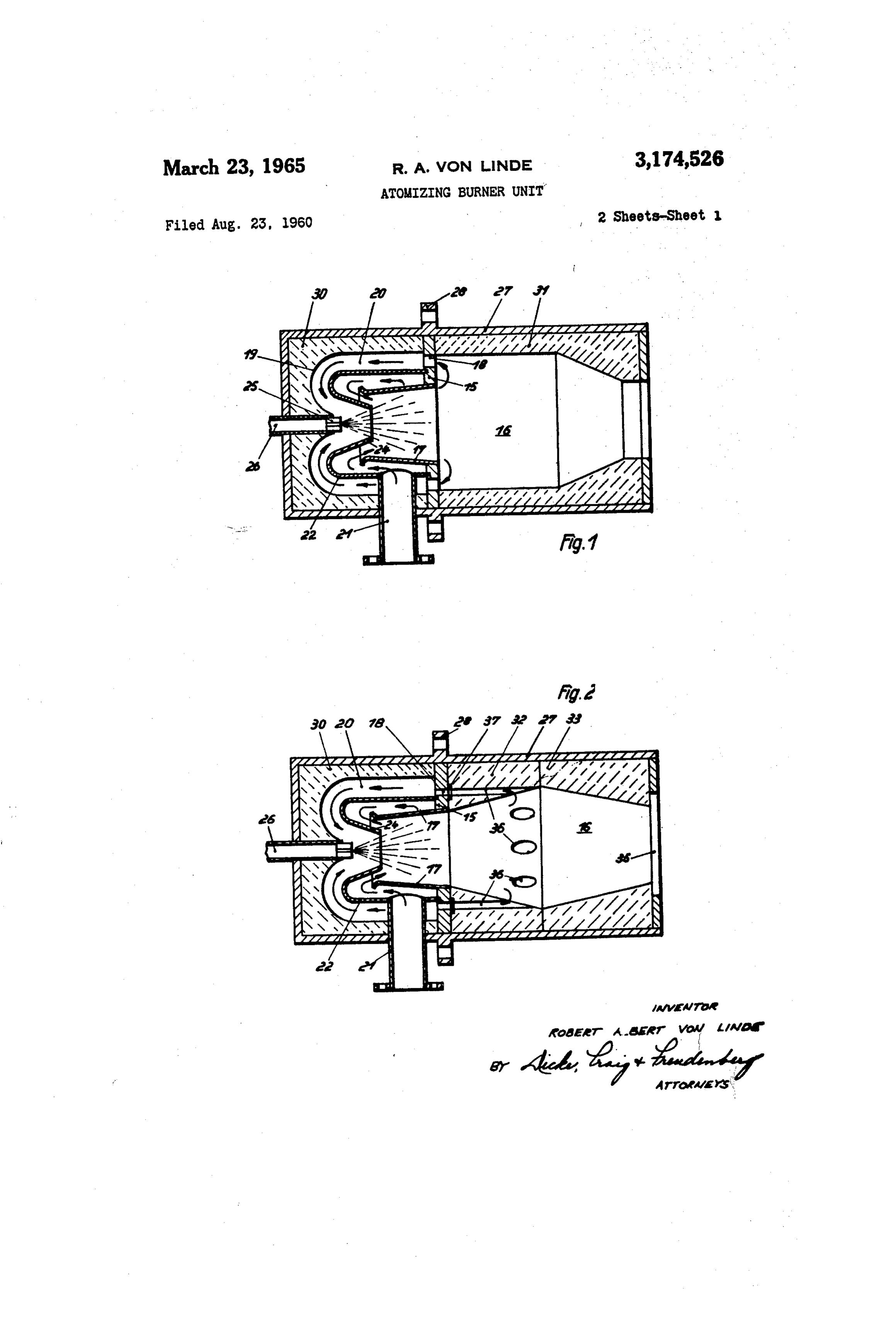
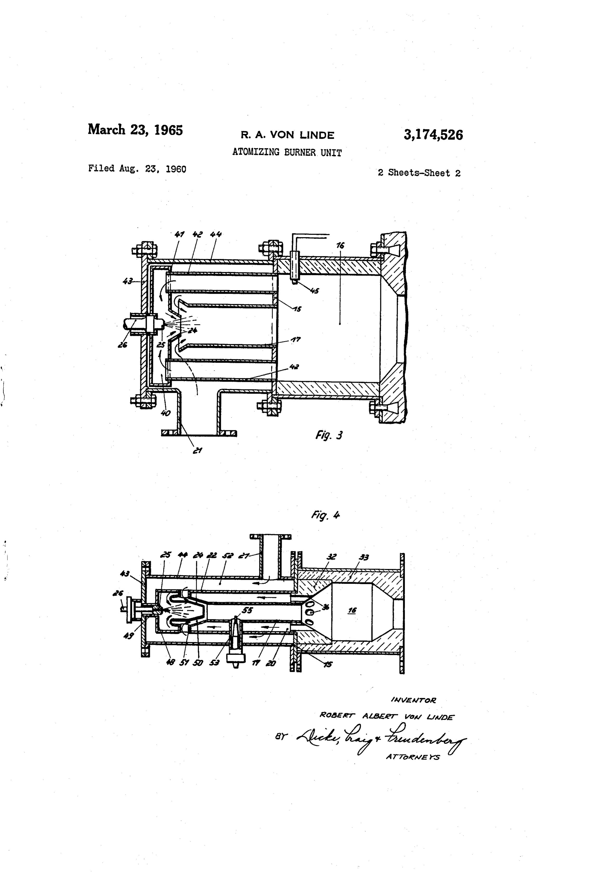
plied thereto and additionally draws or sucks in hot com These and further objects, features and advantages of bustion gases from a chamber in open communication the present invention will become more obvious from the with the combustion space. following description when taken in connection with the With the known burners of this general type, the atom 15 accompanying drawing which shows, for purposes of illus izing nozzle is so arranged that the fluid fuel is atomized tration only, four embodiments in accordance with the within the combustion air stream which is surrounded by present invention and wherein:
a gaseous envelope consisting of drawn-back or sucked FIGURE 1 is a cross-sectional view of a first embodi back combustion gases. ment of an atomizing burner in accordance with the These combustion gases, the thermal contents of which 20 present invention, and could contribute very significantly to the rapid evapora FIGURES 2 through 4 are cross-sectional views, similar tion and preparation of the fuel mist, therefore, intermix to FIGURE 1, of three further modified embodiments of themselves in the known prior art burners only sub atomizing burners in accordance with the present in sequently with the fuel suspended in the combustion air vention. S. and, therefore, can fulfill only incompletely the tasks as 25 Referring now to the drawing, wherein like reference signed thereto. It is true that by preheating the combus numerals are used throughout the various views to des tion air, the preparation of the fuel may be improved ignate corresponding parts, and more particularly to the considerably; however, the heat exchanger installation re embodiment of FIGURE 1, reference numeral 16 des quired therefor would increase considerably the cost of ignates therein a combustion chamber which is limited such an installation. 30 at one end thereof by an annularly shaped flange 5 of These disadvantages are avoided in the present inven a mixing tube or burner pipe 17. Apertures 18 are pro tion by arranging the fuel atomizing nozzle in a pre vided within the annular flange 15 which discharge into chamber, to which is supplied, in accordance with the an annular space 20 limited at the front end thereof by present invention, the part of the combustion gases taken a toroidal surface 19. The inner boundary surface of this from the combustion chamber, and by discharging or ter 35 annular space 20 is constituted by the outer wall surface minating this prechamber in a mixing nozzle to which is of an intermediate jacket or wall 22 to which is connected admitted the combustion air. With such an arrangement, the air supply pipe or conduit 21 and which passes over the combustion gases drawn or sucked-back to the mix into a mixing nozzle 24 arranged concentrically to the ing nozzle may give off the thermal contents thereof at mixing tube or burner pipe 7. A fuel supply line 26 relatively high temperatures directly to the fuel mist 40 provided with an atomizing nozzle 25 terminates in the whereby a very rapid and complete evaporation and mixing nozzle 24. The wall 22 and the mixing pipe 17 preparation of the fuel, as well as an advantageous mix define therebetween an annular channel to which is sup ture formation and therewith a very short and clear flame, plied combustion air through the pipe connecting mem i.e., a flame free of carbon black or soot, is formed. ber 21. The combustion air thereby flows about the These properties are also assured in case when a mix 45 freely exposed end surface of the mixing pipe 17 into ture very rich in combustible contents or constituents is the mixing chamber formed by the pipe 17. As a result supplied to the burner. Consequently, with the burner of its flow energy, the combustion air draws in through according to the present invention not only very high the mixing nozzle 24 the combustion gases together with combustion temperatures may be achieved, which are of the combustible particles of the fuel distributed and pre particularly great value with industrial furnaces, for 50 pared therein which are present in the prechamber 20 and example, for smelting or forging furnaces or the like, but continuously flow through the apertures 18 from the com also gas mixtures may be produced thereby with equally bustion space 16 into the prechamber 20. good combustion which, by reason of the large contents The annular space 20 forming a prechamber is sur in reducing effective component parts form a suitable rounded by a ceramic hollow body. 30 whereas the com furnace atmosphere for the heat treatment, for instance, 5 5 bustion chamber 16 is constituted by the hollow space of of work tools. a fire-proof hollow body member 31. The casing 27 of Accordingly, it is an object of the present invention the burner is provided with a flange 28 by means of which to provide a burner of the type mentioned hereinabove the burner may be so secured at the edge of the firing which eliminates the aforementioned disadvantages en aperture of a heat-consuming device (not illustrated), for countered in the prior art devices and which additionally 60 example, of an industrial furnace or of a gas producer improves the combustion characteristics thereof. which serves for purposes of obtaining neutral or reduc Another object of the present invention is the provision ing gaseous atmospheres that the combustion chamber 16 of an atomizing burner in which the preparation of the extends into the firing space thereof. fuel is considerably improved in a simple manner and The embodiment of FIGURE 2 distinguishes itself from without the necessity of relatively expensive installations 65 the embodiment of FIGURE 1 essentially by the fact such as heat exchangers. that the section of the combustion chamber 6 adjoining Another object of the present invention resides in the the mixing pipe or burner tube E7 is enlarged conically. provision of an atomizing burner arrangement in which This section is formed by the hollow space of a ceramic optimum use is made of the thermal contents of the com body 32. In order to supply a partial stream of com bustion gases drawn back from the combustion chamber 70 bustion gases, required within the meaning of the present into the atomizing unit so as to increase the rapidity and invention for the mixture formation, from the combustion quality of the fuel preparation. chamber 6 to the apertures 18 and therewith to annular 4 prechamber space 20, the hollow body member 32 is pro relatively high flame temperatures may be readily at vided with several channels 36 which, on the one hand, tained.
terminate in the conical inner wall of the hollow body The heat exchange between the Sucked-back combus member 32 and, on the other, in an annular groove 37 tion gases and the combustion air obtained through the facing the apertures 8. The combustion chamber 16 is wall 22 (FIGURE 1) or through the walls of the pipes closed off by a hollow conical portion formed by the sur 42 (FEGURE 3) results in keeping the temperature of the rounding casing part 33 which decreases in cross section combustion gases within the vicinity of the atomizing noz in the direction toward the discharge aperture 35. Zie 25 within a limit favorable for the vaporization and In the embodiment of FIGURE 3, one end each of preparation of the fuel mist. This is so as with exces several tubes 42 are inserted into the flange 15, and IO sive temperatures undesired side reactions may occur at the other end terminate and discharge into a precham which may lead to a cracking of the fuel and thereby lead ber 40 having an end wall 41 provided with a mixing noz to the formation of soot, carbon black, or the like. On Zle 24. The atomizing nozzle 25 is arranged with an the other hand, this heat exchange is effective in such a aperture of the other end wall of this prechamber 40. manner that the combustion air also assumes a tempera A hollow space defined by cylindrical casing 44 and an ture favorable for the operation of the combustion proc end wall 43 serves for purposes of guiding the com SS.
bustion air which thereby absorbs heat from the com While I have shown and described four embodiments in bustion gases sucked in through the pipes 42 out of the accordance with the present invention, it is understood combustion chamber 16 and, therefore, absorbs in a pre that the same is not limited thereto but is susceptible of heated condition the mixture consisting of fuel, mist and 20 many changes and modifications within the spirit and combustion gases. A spark plug 45 of known construc scope thereof, and , therefore, do not wish to be limited tion serves thereby for purposes of igniting the mixture. to the details shown and described herein, but intend to In the burner embodiment illustrated in FIGURE 4, the cover all such changes and modifications as are encom mixing pipe 7 discharges into a conical section 32 of the passed by the scope of the appended claims. combustion chamber 16. A plurality of annularly dis 25 claim:
tributed channels 36 are thereby provided in the walls of 1. An atomizing burner unit, especially for liquid fuels, this section 32. The channels 36 terminate in an annu comprising combustion chamber means, wall means form lar cylindrical prechamber 20, the inner wall of which is ing prechamber means, means to enable combustion gases constituted by the mixing pipe 17 and the outer wall of to pass from said combustion chamber means into said which is constituted by a jacket or wall 22. The wall 22 prechamber means, mixing pipe means in communication is Secured at one end thereof at the annular flange 15 with said prechamber means, means for supplying com and at the other end thereof is closed off by means of an bustion air at relatively high velocities to said mixing pipe end wall 48 into which is inserted a connecting pipe 49 means to thereby draw-in hot combustion gases from said for the insertion therein of the fuel nozzle 25. The mix combustion chamber means through said prechamber ing pipe i7 thereby forms.the forward portion of a cham means into said mixing pipe means, said wall means in ber 50 into which extends a mixing nozzle 24 and which cluding two essentially concentric wall parts surround is in open communication by means of lateral hollow con ing said mixing pipe means constituting therebetween two necting conduit portions 51 with the cylindrical hollow hollow spaces disposed one about the other, of which the space 52. The annular space 52 is thereby defined by the outer space forms said prechamber means in open com flange 15, by the end wall 43 and the cylinder jackets 22 40 munication with said combustion chamber means and and 44 which are provided with an air-supply connecting the inner space forms a part of said means for supplying member 2. A tubular connecting member 53 extending combustion air, a mixing nozzle portion secured to the in in tight sealing arrangement through the tubular walls 44, ner one of said two essentially concentric wall parts and 22 and 17 serves for the support of a spark plug 55. The in communication with said mixing pipe means and hollow body section 32 consisting of ceramic material 45 fuel atomizing means for distributing finely divided fuel forms an inner insert for a hollow body 33 terminating toward said mixing pipe means into the drawn-in com the combustion chamber 16. bustion gases.
Operation 2. An atomizing burner unit, especially for liquid fuels, comprising combustion chamber means, wall means form
The burner in accordance with the present invention ing prechamber means terminating at one end thereof in operates as follows: 50 mixing nozzle means and also forming mixing pipe means The combustion air supplied through the connecting in communication with said mixing nozzle means, said pipe 2 flows with relatively high velocity into the mixing prechamber means being in communication near the other pipe or burner tube 17 and produces thereby at the orifice end thereof with said combustion chamber means to en of the connecting portion or mixing nozzle 24 a vacuum able combustion gases to flow from said combustion cham or underpressure. Consequently, a mixture-stream enters 55 ber means through said prechamber means into said mix into the airstream which mixture-stream reaches the mix ing nozzle means, inducting means including combustion ing nozzle 24 from the combustion chamber 6 along the air Supply means for Supplying combustion air at rela path indicated by the arrows. This mixture-stream ab tively high velocities to said mixing pipe means to thereby sorbs the fuel injected from the nozzle 25 in finely dis draw-in hot combustion gases from said combustion cham tributed form and forms in the first section of the mixing 60 ber means through said prechannber means into said mix pipe a very hot core stream which mixes completely with ing pipe means by the flow energy in said combustion air, the combustion air only shortly ahead of the end of the and fuel injection means arranged in said prechamber mixing pipe 7. By reason of the fact that the liquid means for injecting finely divided fuel into said mixing fuel is injected directly into the hot drawn- or sucked-back nozzle means to be mixed therein with the drawn-in com combustion gases, a very homogeneous, well-prepared bustion gases prior to admixture thereof with said com and, therefore, also completely unobjectionably burning bustion air, said wall means including two concentrically mixture results therefrom which burns even with a short age of air with a short constant fiane without the forma arranged wall portions and a third wall portion forming tion of soot and carbon black, and which supplies a mix said mixing pipe means, said two first-mentioned wall por ture usable as furnace atmosphere having a high con 70 tions and said third wall portion forming therebetween tent in reducing gas particles. If the stoichiometric quan two hollow spaces disposed one about the other, the tity of air, i.e., the quantity of combustion air exactly outer of which constitutes a portion of said prechamber necessary for complete combustion of the supplied fuel means and the inner of which constitutes a portion of said quantity, is supplied to the burner, there results the ac combustion air supply means.
vantage in accordance with the present invention that 5 3. An atomizing burner unit according to claim 2, 5 wherein said fuel injection means includes atomizing said air supply means including an annular gap provided nozzle means arranged essentially concentrically to said between said second and third wall portions for the admis mixing nozzle means. sion of the combustion air into said mixing pipe means. 4. An atomizing burner unit according to claim 2, 6. An atomizing burner unit comprising a mixing sec wherein said mixing pipe means terminates in a section of tion having an upstream end, a mixing nozzle disposed said combustion chamber means which increases conically essentially coaxially to and partially within said upstream in cross section in the direction of flow of the combustion end of said mixing section, a combustion section, return gases, said section having an inner wall provided with conduit means extending rearwardly from said combus channels in communication with the prechamber means tion section into communication with said mixing nozzle and with said combustion chamber means. to supply hot combustion gases essentially equally around 5. An atomizing burner unit, especially for liquid fuels, the periphery of said mixing nozzle, fuel atomizing means comprising combustion chamber means, wall means form disposed essentially coaxially to said mixing nozzle for ing prechamber means terminating at one end thereof in dispersing finely divided fuel into the hot combustion gases mixing nozzle means and also forming mixing pipe means passing through said mixing nozzle to vaporize said fuel in communication with said mixing nozzle means, said prior to admixture with combustion air, said upstream prechamber means being in communication near the other end of said mixing section being spaced from said mixing end thereof with said combustion chamber means to en nozzle to provide passage means therebetween, and con able combustion gases to flow from said cornbustion cham duit means for supplying combustion air into said passage ber means through said prechamber means into said means for educting hot combustion gases and dispersed mixing nozzle means, inducting means including combus 20 fuel vaporizing therein from said mixing nozzle into tion air Supply means for supplying combustion air at said mixing section.
relatively high velocities to said mixing pipe means to 7. An atomizing burner unit according to claim 6, thereby draw-in hot combustion gases from said combus wherein said return conduit means include a plurality of tion chamber means through said prechamber means into spaced tubular members.
said mixing pipe means by the flow energy in said corn bustion air, and fuel injection means arranged in said pre References Cited in the file of this patent chamber means for injecting finely divided fuel into said UNITED STATES PATENTS mixing nozzle means to be mixed therein with the drawn 687,535 Machlet --------------- Nov. 26, 1901 in combustion gases prior to admixture thereof with said 2,048,321 Carruthers et al. --------- July 21, 1936 combustion air, said wall means including a first wall por 2,701,608 Johnson ---------------- Feb. 8, 1955 tion constituting an inner wall of said prechamber means 2,722,372 Edwards ---------------- Nov. 1, 1955 and a second wall portion rigidly connected with said first 2,734,560 Harris et al. ------------ Feb. 14, 1956 wall portion and constituting said mixing nozzle means, and a third wall portion forming said mixing pipe means FOREIGN PATENTS and defining in conjunction with said first and second wall 3.5 1,044,190 France ----------------- June 17, 1953 portions a passage forming part of said air supply means,
Provenance
- Collection
- Patents citing this work
- Pages
- 5
- Method
- pdftotext (the PDF's own text layer) + pdftoppm 300dpi page scans
- Patent office record
- patents.google.com →
- Source
- Google Patents citing-documents table
- Assignee
- Linde Robert Albert Von
- Published
- 1965-03-23
- Transcribed from
- patentimages.storage.googleapis.com →