

patent · US3185871A
Alternating current magnetohydrodynamic generator
25 May 1965
Text
Drawings
Page 1drawing sheetscan →
Page 2drawing sheetscan →
Page 3drawing sheetscan →
Page 4scan →
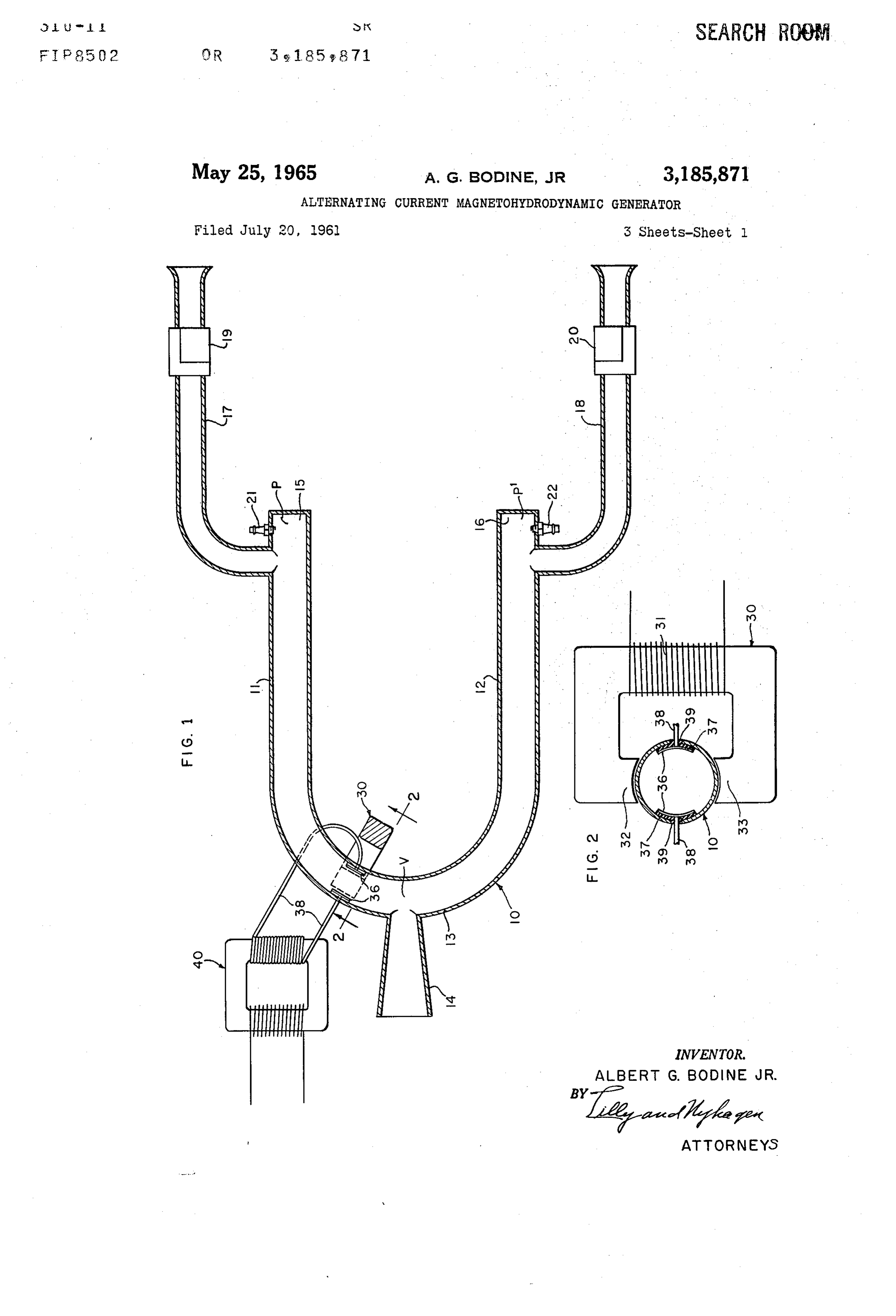
United States Patent Office 3,185,871 Patented May 25, 1965 basic essentials, is similar to that shown in FIG. 17 of 3,185,871 my aforesaid Patent No. 2,796,735, and reference may be ALTERNATING CURRENT MAGNETO HYDRO had to said patent for a complete description of all details DYNAMIC GENERATOR of said engine. In FIG. 1, numeral 10 designates gener Albert G. Bodine, Jr., Sherman Oaks, Calif. ally a U-shaped sonic pipe, having legs 11 and 12 con (7877 Woodley Ave., Van Nuys, Calif.) nected by semi-circular pipe section 13, the latter having,
7 Claims. (Cl. 310-11) opening from the midpoint of its convex side, a fluid dis charge outlet or tailpipe 14. The closed head end regions
This invention relates generally to the art of magneto 15 and 16 of the two legs 11 and 12 form fuel combustion hydrodynamics, wherein a conductive fluid travelling O chambers, to which gaseous or fluidized fuel (any of the through a magnetic field generates electrical current at fossil fuels) is fed through induction pipes 17 and 18, right angles to the magnetic field and to the direction of respectively. Air to support combustion enters the for fluid flow. The conductive fluid can be a hot ionized gas. ward open ends of the pipes 7 and 18, and fuel is Sup Such generators, as heretofore known, deliver a direct plied by carburetors 19 and 20, respectively. Combusti current output. 5 ble mixtures are thus formed which are conveyed via the The primary object of the present invention is to pro pipes 17 and 18 to the combustion chambers 15 and 16, vide a magnetohydrodynamic generator which delivers an respectively. These two induction pipes 17 and 18 are alternating current output, valveless, and to work without valves, have certain neces The invention accomplishes this objective by using, in sary impedance characteristics such as fully disclosed in its preferred illustrative form, in lieu of the usual uni 20 my prior Patents Nos. 2,731,795 and 2,796,735, and the directional ionized gas flow through the gas channel con disclosures of which are incorporated herein by reference. taining the magnetic field and output electrodes, an ionized The combustion chamber end portions of the two legs gas column wherein is maintained a sonic standing wave, 11 and 12 are furnished with spark plugs 21 and 22, and with a velocity antinode region of the standing wave at these are energized cyclically in 180 opposition, each at the location of the magnetic field and output electrodes. 25 the resonant frequency of the pipe 10. These spark plugs The velocity antinode region of a sonic standing wave may be energized by any suitable synchronized ignition is one wherein the gas flow periodically reverses direction system, for instance as disclosed in FIG. 1 of the aforesaid in the gas flow channel or conduit. It follows that an Patent No. 2,731,795.
alternating current is delivered from the generator. By energizing the spark plugs cyclically, in 180 op An advantageous system in accordance with the inven 30 position, each at the resonant frequency of the pipe 10, the tion for generating the sonic standing wave is driven by fuel charges delivered to the combustion chamber regions periodic combustion of fuel, and is controlled by auto 15 and 16 are exploded alternately, so as to send pressure resonance to produce the standing sound wave of the de pulses through the column of gas contained in the U-tube, sired frequency. Examples of heat engines embodying alternately from one end of the U-tube to the other, the such principles are disclosed in my prior Patent No. 2,796 35 resonant occurrence of the explosions causing a standing 735. In these engines, the gas velocities attained in the wave to be established in the pipe with pressure antinodes combustion gas conduits at the velocity antinodes therein P and P' at the two combustion zones, and with a velocity are of the order of the speed of sound. As will appear, antinode V in the pipe adjacent the outlet 14. As ex the present invention may be practiced by creating a mag plained in the aforesaid patents, it is necessary only to netic field across the gas conduit at a velocity antinode 40 use a spark plug for starting, the cyclic process being region in any of the embodiments disclosed in said patent, Amaintained thereafter with interaction between the com and taking the electric current off in the velocity antinode bustion and the sound wave.
region at right angles to the magnetic field. It is of In the operation of the apparatus, fuel and air mixture course obvious that many gas conduit configurations in thus enters the two combustion chambers via the two in which gas oscillation can be established and maintained, 45 duction pipes and these mixtures are alternately exploded in addition to those illustrated in my Patent No. 2,796,735, to establish the standing wave already mentioned. For may be employed in carrying out the invention. a more detailed discussion of standing wave phenomena, As regards the source of ions in the oscillating gas reference may be had to my aforesaid Patents 2,739,795, column, the practice may be the same as heretofore pro and 2,796,735. At the velocity antinode region V, prod posed for magnetohydrodynamic generators, including 50 ucts of combustion oscillate back and forth around the heating, and “seeding' with substances such as potassium curved pipe section at maximized velocity and at resonant powder. Combustion gases are ionized to a Substantial frequency. Thereby, centrifugal force effects are de extent in any event, and any suitable additives to the fuel veloped which crowd these oscillating gases to the outer such as will improve the source of ion concentration may side of the curved pipe section. There, the outer layers be employed. With many fuels, the naturally occurring 55 of the oscillating gases reach and are forced out the tail impurities are sufficient to provide adequate additional pipe, first, by reason of centrifugal force, and second, by ionization. reason of the oscillating gas particles being intercepted and In the drawings, which show a number of selected illus deflected outward by the sharp edges at the junction of the trative embodiments of the invention: pipe 10 with the flaring tailpipe 14. These provisions for FIG. 1 is a diagrammatic view, in longitudinal section, 60 inducing discharge of combustion gases create the neces showing one illustrative form of the invention. sary pressure gradient or differential between the tail FIG. 2 is a section taken as indicated by line 2-2 of pipe 14 and air intake pipes 17 and 18 for pumping of air FIG. 1; through the system without the necessity of blowers. Of FIG. 3 is a longitudinal section view of an earlier em course, optionally, though not necessarily, blowers can be bodiment of the invention, again shown in diagrammatic 65 used in the intake pipes as suggested in Patent No. 2,731 form; 795 (see FIG. 1).
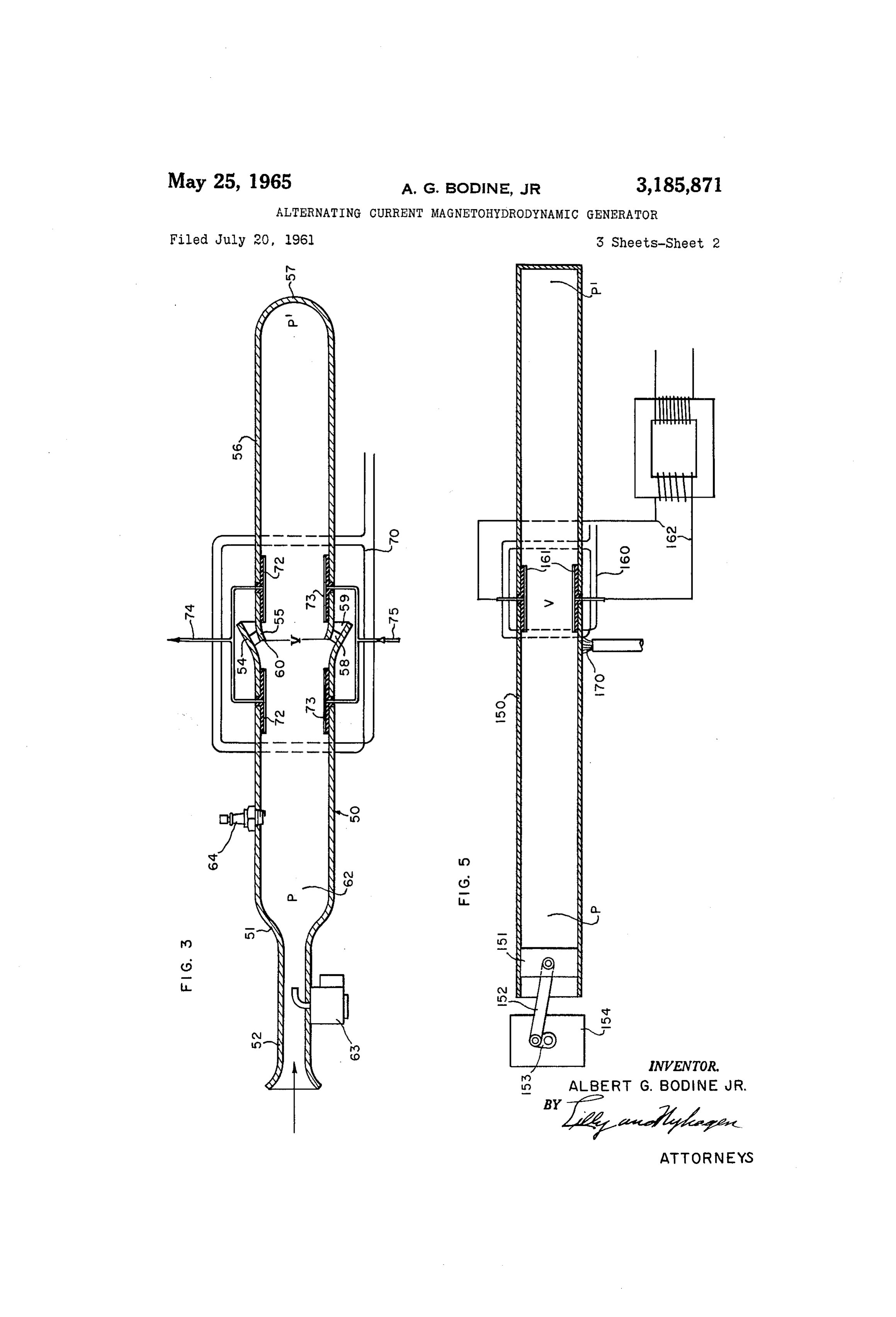
FIG. 4 is a diagrammatic view, partly in elevation and The apparatus as heretofore described is old, and the partly in section, showing another illustrative embodiment improvements of the present invention will now be de of the invention; scribed. Within the extent of the curved section 13 of FIG. 5 is a diagrammatic view of another illustrative 70 the U-tube 10, i.e., in the region of the velocity antinode embodiment of the invention. V, a means is provided for creating a magnetic field FIGS. 1 and 2 show an acoustic heat engine which, in transversely across the interior of the pipe, and a second 5 means is provided for taking off electrical current flow passage 59 for discharge of products of combustion. from the gases in the pipe in a direction transversely of The convergent portion 55 of pipe 56 will be seen to ter the pipe but at right angles to that of the magnetic field. minate at its forward end in an annular edge 60 spaced As here shown, the core of an electromagnet 30, having inside the pipe 50, and in a position to intercept a por winding 31, has opposed pole pieces 32 and 33 positioned tion of the oscillating gas particles travelling from left on opposite sides of the pipe 10 in the velocity antinode to right at the juncture of the pipes 50 and 56. As will region V, such that a magnetic field is created between be seen, the portion of the gas intercepted by the edge these pole pieces. The pipe 10 is made of some low mag 60 is deflected into the annular gas discharge passage 59 netic permeability material, such as stainless steel, so and so discharged to atmosphere in a generally outward that a substantial magnetic field extends inside the pipe IO and rearward direction. It is by this means that the and transversely across the gas conduit. Mounted in the gases are pumped through the system without use of a pipe in the area of this field are a pair of current collector blower.
electrodes 36. These are mounted adjacent opposite sides The head end region 62 of pipe 50 forms a combus of the pipe wall, centered on an axis perpendicular to the tion zone, wherein fuel, supplied to intake pipe 52 as by direction of the magnetic field, and, as diagrammatically 5 carburetor 63, together with air taken into the intake shown, are electrically insulated from the pipe by heat pipe and supplied to the region 62, are periodically resistant ceramic insulators 37. Electrical conductors 38 burned. To instigate combustion, a spark plug 64 is em engage the collector electrodes 36 and extend outwardly ployed, energized by any suitable ignition system, not nec through the side wall of the pipe through nipples 39 essary to illustrate herein.
formed on insulators 37. The conductors 38 are con 20 The pipe sections 50 and 56, taken together, form a nected to the primary of a suitable transformer 40, the half-wavelength resonant acoustic pipe, the section 50 output or secondary winding of which may step the volt and 56 being each of one quarter wavelength. Periodic age either up or down depending upon the application in explosions taking place in the combustion region 52 at hand. Since the output from the generator is character the resonant frequency of members 50 and 56 set up an istically at high current flow, the transformer will gen acoustic standing wave action, producing a pressure anti erally be a voltage step-up type to deliver a high voltage node P at the combustion region, and a velocity antinode suitable for transmission. V at the end of pipe section 50. Pipe section 56 is of The operation of the system should now be evident. the same effective length as pipe section 50, and accord The gas column in the U-tube will consist of ionized ingly, a pressure antinode P' is established at the closed gases, either ionized by reason of the combustion process, 30 end of pipe section 56. Under these circumstances, peri or preferably containing a higher concentration of ions odic pressure pulses, at the resonant frequency of the than can thereby be attained through use of fuel addi pipe sections, are developed by intermittent combustion tives. As already explained, the combustion gases in the at Zone 62, causing periodic pressure peaks at regions P curved portion of the U-tube are in a velocity antinode and P', and oscillating gas flow longitudinally of the region, and are therefore undergoing rapid oscillation, pipe sections 50 and 56 at region V. travelling longitudinally around the curve first in one An electrically energized field coil 70 positioned on the direction and then the other. With the gas travelling outside of the pipe section 50 and 56 in the region V in one direction, it will, in passing through the previously establishes a magnetic field transversely through the gas described magnetic field, set up an electrical current flow column region V where the gases are maintained in os at right angles to the magnetic field and to the direction 40 cillation. As viewed in FIG. 3, this magnetic field is per of gas flow, and this current flow, or flow of gas ions, is pendicular to the plane of the paper. The ends of the picked up by the spaced collector electrodes 36 and passes coil may be curved to conform to the pipe. Of course, through the external circuit including the primary wind an electromagnet such as shown in FIGS. 1 and 2 may be ing of transformer 40. When the gas flow reverses direc used if desired. It will be understood that the pipe sec tion, the current flow also reverses direction. Thus an 45 tions 50 and 56 are of some non-magnetically permeable alternating current flow is generated in the primary cir material, so as to permit a good magnetic field inside the cuit of the transformer and is delivered from the sec gas conduit.
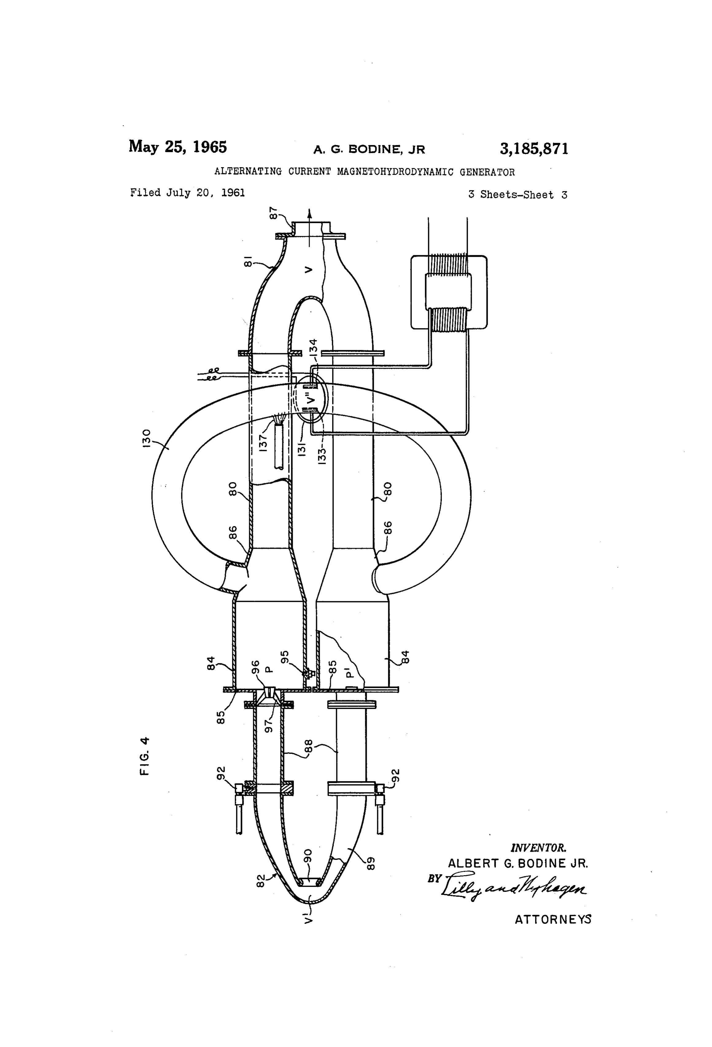
ondary circuit thereof, usually stepped up in voltage. The direction of the magnetic field being perpendicular It may be mentioned that the combustion driven sound to the plane of the paper, the path of generated current Waves of the system tend to generate certain harmonic 50 flow will be in the plane of the paper, and at right angles frequencies, which may appear in the alternating current to the direction of gas flow. In other words, as seen in output. These, however, can be filtered out by means of FIG. 3, the current flow direction is vertical. Accord techniques well understood in the electrical art, so that a ingly, collector electrodes 72 and 73 are positioned adja good sine wave output is available. In general, it is cent the upper and lower walls of the pipes, extending undesirable to attempt prevention of harmonic frequen 55 throughout the general oscillation region V, each being cies in the sonic system, because these harmonic fre in the present instance, divided into two halves located quencies have been found to be of benefit to the com on opposite sides of the intermediate gas outlet passage. bustion process. The upper electrodes 72 are connected to an output con FIG. 3 shows the application of the invention to a ductor 74, and the lower electrodes 73 are connected to Straight tube type of Sonic combustion heat engine, such 60 an output conductor 75, and it will be understood that the as shown in FIG. 18 of my prior Patent No. 2,796,735. conductors 74 and 75 are the output terminals of the gen Only a brief description of this heat engine will be given, erator, and may, if desired, be connected to the primary a reference to said patent may be had for a more com of a transformer. It will further be understood that the plete understanding. In FIG. 3, numeral 50 designates output current will reverse direction periodically, in step generally a gas conduit or pipe, of generally cylindrical 65 form, having a head portion 51 into which opens fuel with the reversal of direction of gas flow in the velocity antinode region V.
and air intake pipe 52. The rear end of pipe 50 is flared It was mentioned in the introductory portion of this or formed with a skirt portion, as indicated at 54, and specification that additives can be introduced into the received within this skirt portion, and annularly spaced combustion fuel in order to improve the degree of ioniza therefrom, is the convergent forward end portion 55 of 70 tion. In the heat engines previously described, the com a conduit or pipe extension 56, provided with a closure bustion gases are constantly being discharged from a 57 at the far end, the portion 55 forming a gas deflecting region relatively close to the point of utilization of the Wall element. The skirt part 54 of pipe 50 and the con ions present, and an inevitable result is some loss of vergent portion or gas deflector 55 of pipe 56 are con ionized particles. In the heat engine now to be disclosed, nected as by means of Webs 58, leaving an annular gas 75 the point of utilization of the ions is located in a portion 6 of the apparatus remote from the point of combustion 84 are of approximately one-quarter wavelength for a products discharge, giving the benefit of easier main desired component of the resonant standing wave fre tenance of high ion concentration in the portion of the quency of the twin burner pipes 80 connected by the tail apparatus where the ions are utilized. With reference pipe fitting 81, difference in temperature of gases in the to FIG. 4, the heat engine shown is in basic respects sim air intake pipe system and in the burner pipes being taken ilar to that disclosed in FIG. 22 of my aforementioned into account. A resonant standing wave accordingly is Patent No. 2,796,735, and a reference may be had thereto set up in the air intake pipe system, with a velocity an for detailed discussion. tinode appearing at V. Gas oscillation at resonant fre The engine of FIG. 4 has two parallel burner pipes 80, quency accordingly occurs about the sharp bend of the air interconnected by a tail pipe fitting 8 at one end of the O intake pipe system, opposite the air intake port 90. apparatus, and by a U-tube, or V-tube, valveless air in Combustion gas discharge is effected from the system take means 82 at the opposite end of the apparatus. Each through the tail pipe discharge orifice 87, aided by cen burner pipe 80 has a forward enlarged combustion cham trifugal force effects as explained in connection with FIG. ber portion 84, closed by forward head wall 85, and a 1. Air intake into the valveless air feed system 82 occurs tapered portion 86, as shown. The tail pipe fitting 81 5 inwardly through the air intake port 90, by reason of has two arms flange-fitted to the rearward ends of the centrifugal force effects owing to gas oscillation at V. two burner pipes, and is in the general form of a Y, the The engine of FIG. 4 as thus described is exactly like two arms communicating with one another to form a that of FIG. 22 of the aforesaid Patent No. 2,796,735. continuous gas conduit connecting the rearward ends of In accordance with the present invention, it is modified the two burner pipes 80, and the stem forming the tail 20 by connecting into burner pipes 80, preferably in the pipe outlet. Gas travelling from one of these arms to the tapered regions 86 just rearwardly of the combustion other will be seen to make a 180° turn. The fitting 81 chambers, the two ends of a loop pipe 130, whose effective has a rearwardly directed orifice member 87 through length is equivalent to the distance around a U-shaped which products of combustion are jetted. path defined by the pipes 80 and fitting 81, rearwardly of The air intake assembly 82 is in the general form of a 25 the junctions between the pipe 130 and the pipes 80. U-tube or V-tube, having two leg portions 88 connected This auxiliary loop pipe 130, which is in parallel with into head 85, and joined by a 180° return bend fitting 89, the gas column down the pipes 80 and around fitting 81, which, in the embodiment of FIG. 4, is somewhat pinched contains a branch column of combustion gas, and a branch so as to reduce the radius of curvature of the bend. The standing wave appears in this branch column, driven two legs of fitting 89 are also preferably gradually con 30 from the alternate combustion in chambers 84. A veloc stricted toward their forward end juncture, as shown. An ity antinode V', i.e., a region of maximized gas oscilla air intake port 90 opens into the fitting 89 at its inner side, tion, occurs in the mid-region of pipe 130. i.e., between its two legs, and the intake air is fed via A field coil 13, generally like that of FIG. 3, energized the two legs of said fitting and the pipes 88 into the com 35 by an electric current, or an electromagnet as in FIGS. 1 bustion chambers 84. and 2, creates a magnetic field transversely, (perpendic Fuel for combustion may be introduced into the system ular to the paper) across the pipe in the region V', and in various ways, but is here shown as injected by means collector electrodes 133 and 134, spaced across the pipe of fuel injectors 92, in such a way that fuel is injected along a line at right angles to the direction of the mag into the air streams entering the pipes 88 leading into 40 netic field, collects the current flow developed. Leads the combustion chambers 84. connected to these electrodes may energize the primary Fuel so introduced into the air intake system and con winding of a transformer as in FIG. 1. A gas flame 137 veyed thence to the chambers 84 is ignited in the latter, is diagrammatically indicated as heating the pipe 130 in and ignition may be initiated by means of a spark plug 95 the region of the velocity antinode V'. This locally ap mounted in the side wall of one of the chambers 85. plied heat desirably increases the temperature of the hot Once ignition has been initiated, a flame lingering in the gases at the locality where the current is generated. combustion chamber between explosions is available to It will be seen that in the generator of FIG. 4, the gases burn successive fuel charges, and electric ignition is no oscillating in the current generating branch pipe 80 are not longer required. To aid in the retention of this flame be in the vicinity of a discharge outlet to atmosphere, and tween explosions, a turbulizer and flame holder 96 is pref hence it is possible to reduce the loss of ion contributing erably employed at the head end of the combustion cham 50 additives which have been incorporated in the fuel. ber, consisting in this instance of a small cone supported In FIG. 5 is shown a modification in which gas oscilla by webs 97. This cone affords a protected region wherein tions are generated by a piston, rather than a combustion the flame is maintained in an attenuated state between process. A gas filled sonic pipe 150 has a piston 151 fitted explosions. It is found in practice that a spark plug need for reciprocation in one end thereof, the other end of the be used in only one of the two combustion chambers, 55 pipe 150 being closed. Piston 151 is driven through con since flame in one of the burner pipes will reach fuel in necting rod 152 from crank 53 on the rotating shaft of the other, and when the latter has once been exploded, any suitable power source 154, such as an engine. The flame thereafter resides in both chambers 84, and is avail gas column in pipe 150 is a half wavelength long for the able to set of the accumulating fuel charge whenever the frequency of oscillation of the piston 151, so that a half pressure within the combustion chamber is sufficiently 60 wavelength standing wave is set up in the pipe, with pres elevated by the standing wave pressure cycle therewithin Sure antinodes P and P' at the ends, and a velocity anti for the desired explosion to occur. node region V at the mid-portion of the gas column. Assuming air for combustion to be fed to the two com A current carrying coil 160 provides a magnetic field transversely bustion chambers 84 through the described air intake 65 current collector across the pipe column in the region V, and electrodes 161 are spaced from one an means, fuel to be injected into this air, and preliminary other across the interior electric ignition to be provided, a resonant standing wave of the pipe along an axis at right is established in the two burner pipes, similar to that de angles to the direction of the magnetic field. These col scribed in connection with FIG. 1, and need not be again lector electrodes have output leads 162 which may go to a transformer, as in earlier described forms of the in described, excepting to note that a velocity antinode region 70 vention.
V appears in the tail pipe fitting 81 as indicated, and There is also shown in FIG. 5 a source 170 of heat, such pressure antinode regions P and P' appear at the head as a flame, applied to the velocity antinode region. This ends of the combustion chambers 84. The combustion head accomplishes ionization of the gases, and con cycle is as in FIG. 1. The lengths of the two air intake ductivity.
paths from the intake port 90 to the combustion chambers 75 As in the earlier embodiments, the reversing ionized gas 7 flow in the gas oscillation region V generates an alternat combustion chambers, means for igniting the mixture in ing current between the collector electrodes 61 and the at least one of said chambers, a combustion products leads 162. discharge outlet in the mid-region of said conduit, all in My Sonic magnetohydrodynamic generator has many Such manner that a half wavelength standing wave is estab advantages over those heretofore known, including: (1) lished in said conduit with pressure antinodes at said com generation of A.C. current, (2) no blowers and other bustion chambers, and a velocity antinode at said mid mechanical moving parts are essential, (3) ion contribut region of Said conduit, means for setting up a magnetic ing additives are conserved, and (4) gas temperatures in field transversely across said gas column in said conduit the current generation region are conserved. in the region of said velocity antinode, whereby an alter A number of my preferred magnetohydrodynamic gen O nating electric current flows transversely across said gas erators have now been described. It will be understood, column at right angles to said magnetic field, and collector however, that these are for illustrative purposes only and means and an output circuit for said alternating current. that numerous changes in design, structure and arrange 5. In a magnetohydrodynamic generator, the combina ment may be made without departing from the scope of tion of: a gas conduit containing a gas column of half the appended claims. 5 Wavelength for a predetermined resonant standing wave I claim: frequency, said conduit having a fuel combustion chamber 1. In a magnetohydrodynamic generator, the combina at each of its ends, means for feeding fuel and air to said tion of: a conduit containing a column of gas, means for combustion chambers, means for igniting the mixture in Setting up and maintaining in said column a longitudinal at least one of said chambers, whereby ionized combus Sonic standing wave, with at least one velocity antinode 20 tion gas products are released to said conduit, a combus therealong, means for ionizing at least that portion of the tion products discharge outlet in the mid-region of said gas in the region of said velocity antinode, means for conduit, a gas containing branch conduit having two ends setting up a magnetic field transversely across said gas joining the first mentioned conduit at two points upstream column in said conduit in the region of said velocity from and on opposite sides of said outlet, and of a length antinode, whereby an alternating electric current flows 25 Such that the distance between combustion chambers transversely across said gas column at right angles to said measured via said branch conduit is of the order of a half magnetic field, and collector means and an output circuit Wave length, whereby a velocity antinode is created in for said alternating current. said branch conduit, means for setting up a magnetic field 2. The subject matter of claim 1, including a source of transversely across said branch conduit in the region of local heat for the velocity antinode region of said gas 30 said velocity antinode therein, whereby an alternating column. electric current flows transversely across said gas column 3. In a magnetohydrodynamic generator, the combina at right angles to said magnetic field, and collector means tion of: a conduit containing a column of gas, means for and an output circuit for said alternating current. setting up and maintaining in said column a longitudinal 6. The Subject matter of claim 5, including also a means sonic standing wave, with at least one velocity antinode 35 for locally heating the gas column in said branch conduit and one pressure antinode therealong, said means for set in the vicinity of said velocity antinode therein. ting up and maintaining said standing wave comprising 7. The Subject matter of claim 1, wherein said standing means for intermittently burning fuel charges in said gas wave has a pressure antinode therein, and said means for column in the region of Said pressure antinode, means 40 Setting up and maintaining said standing wave comprises for setting up a magnetic field transversely across said gas a reciprocating piston in said conduit in the general region column in said conduit in the region of said velocity anti of said pressure antinode.
node, whereby an alternating electric current flows trans References Cited by the Examiner Versely across said gas column at right angles to said mag netic field, and collector means and an output circuit for
United states patents
Said alternating current. 1,916,076 6/33 Rupp ----------------- 310-11 4. In a magnetohydrodynamic generator, the combina 2,796,735 6/57 Bodine -------------- 60-39.77 tion of: a gas conduit containing a gas column of half 3,034,002 5/62 Carlson --------------- 310-11 Wavelength for a predetermined resonant standing wave frequency, said conduit having fuel combustion chambers 50 MILTON O. HERSHFIELD, Primary Examiner. at each of its ends, means for feeding fuel and air to said DAVID X. SLINEY, Examiner.
Provenance
- Collection
- Patents citing this work
- Pages
- 7
- Method
- pdftotext (the PDF's own text layer) + pdftoppm 300dpi page scans
- Patent office record
- patents.google.com →
- Source
- Google Patents citing-documents table
- Assignee
- Jr Albert G Bodine
- Published
- 1965-05-25
- Transcribed from
- patentimages.storage.googleapis.com →