

patent · US3194296A
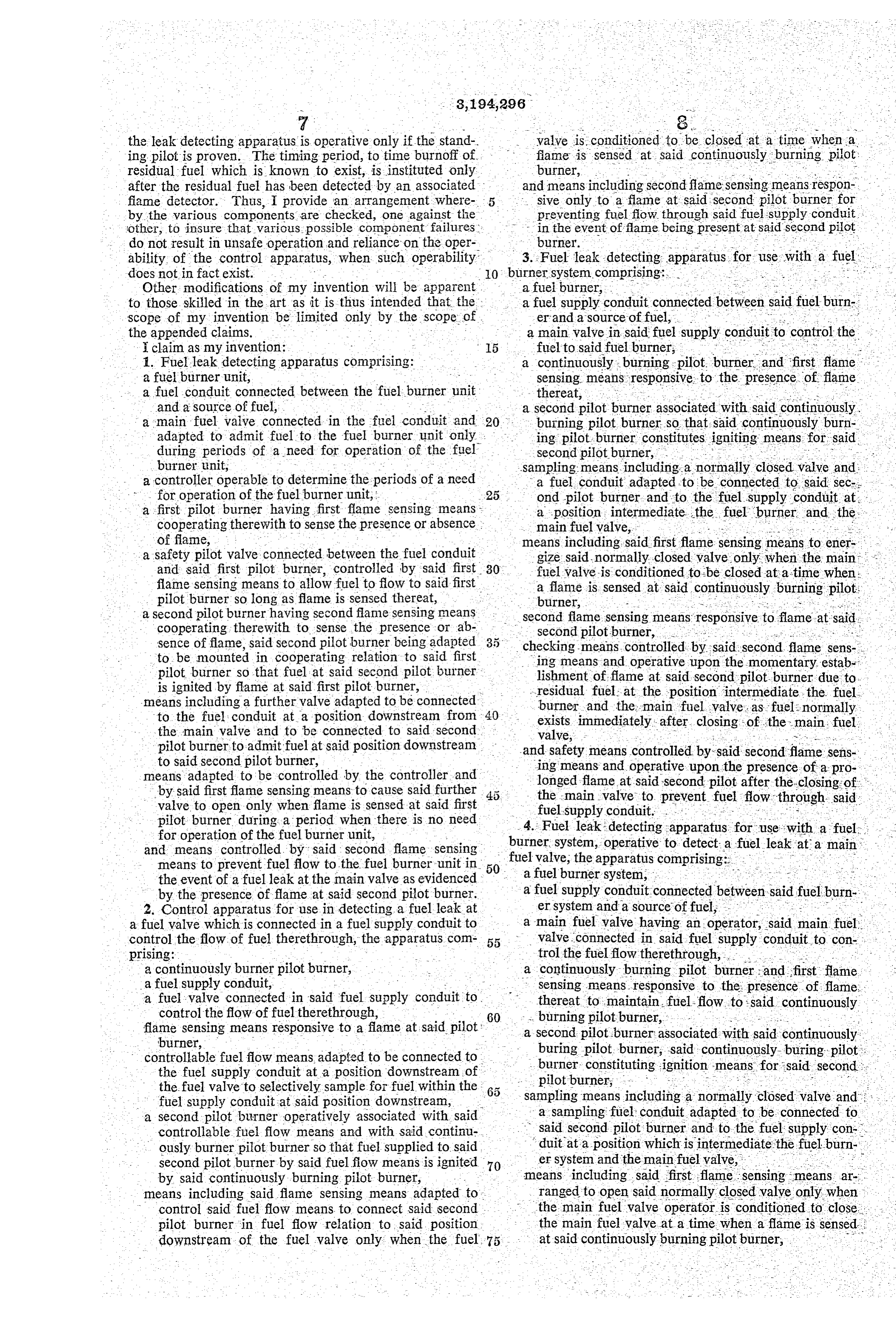
Control apparatus
13 July 1965
Text
Drawings
Page 1drawing sheetscan →
Page 2drawing sheetscan →
Page 3drawing sheetscan →
Page 4scan →
United States Patent Office Patented July 13, 1965 mentary fame is produced. The structure of my apparatus 3,194,296 requires that the flame detecting means associated with CONTROL, APPARATUS the leak detecting pilot must detect this momentary Richard W. Brown, Exceisior, Minia, assigaror to flame to insure that the flame detecting means is in Honeywell Inc., a corporation of Delaware fact operative and is capable of detecting a flame. Filed July 26, 1963, Ser. No. 297,90 Furthermore, I provide a timer which is energized only after the flame detecting means detects this residual
My invention is concerned with an improved control amount of fuel downstream of the main valve, the timer apparatus and particularly a control apparatus which is being conditioned to provide a tinning period for burnoff adapted for use with a fuel burner installation to check of this residual fuel. As a result the apparatus of my and Supervise a fuel valve of a fuel burner installation invention indicates a leaky valve, sounds an alarm, or and to sound an alarm or the like if a leak should occur closes a further safety valve which is upstream of the at this valve. main valve, only when a sustained flame exists at the As is well known, fuel burner installations may utilize leak detecting pilot after this timing period. various arrangements of ignition means, pilot means, 5 With these general observations in mind, my invention main burners and blower to provide safe lightoff and will be apparent to those skilled in the art upon reference operation of the main burner, under the control of a to the following specification, claims, and drawing, of controlling device responsive to the need for operation of which:
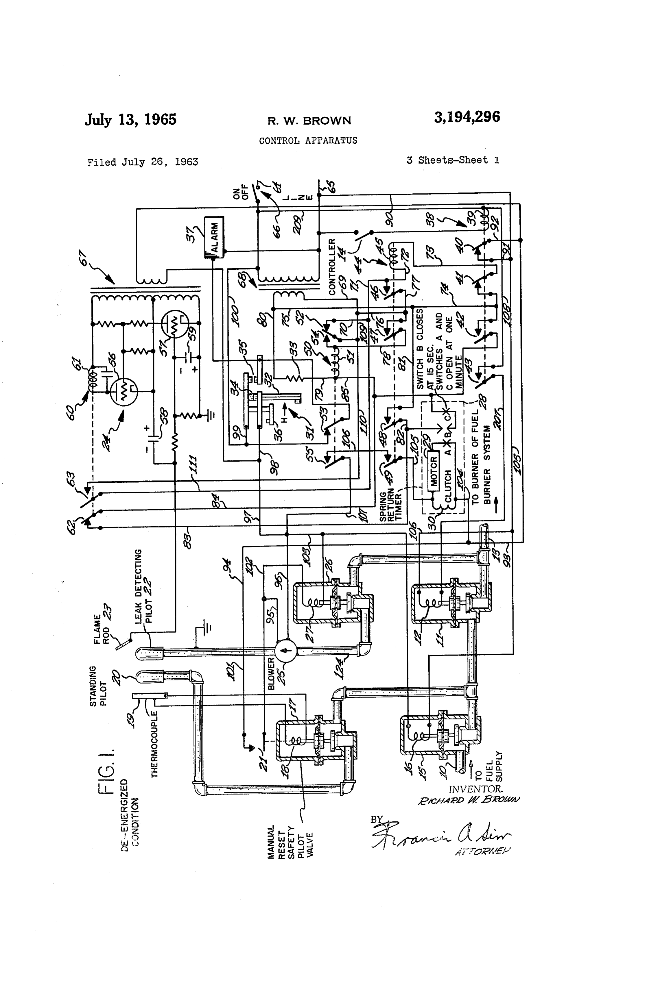
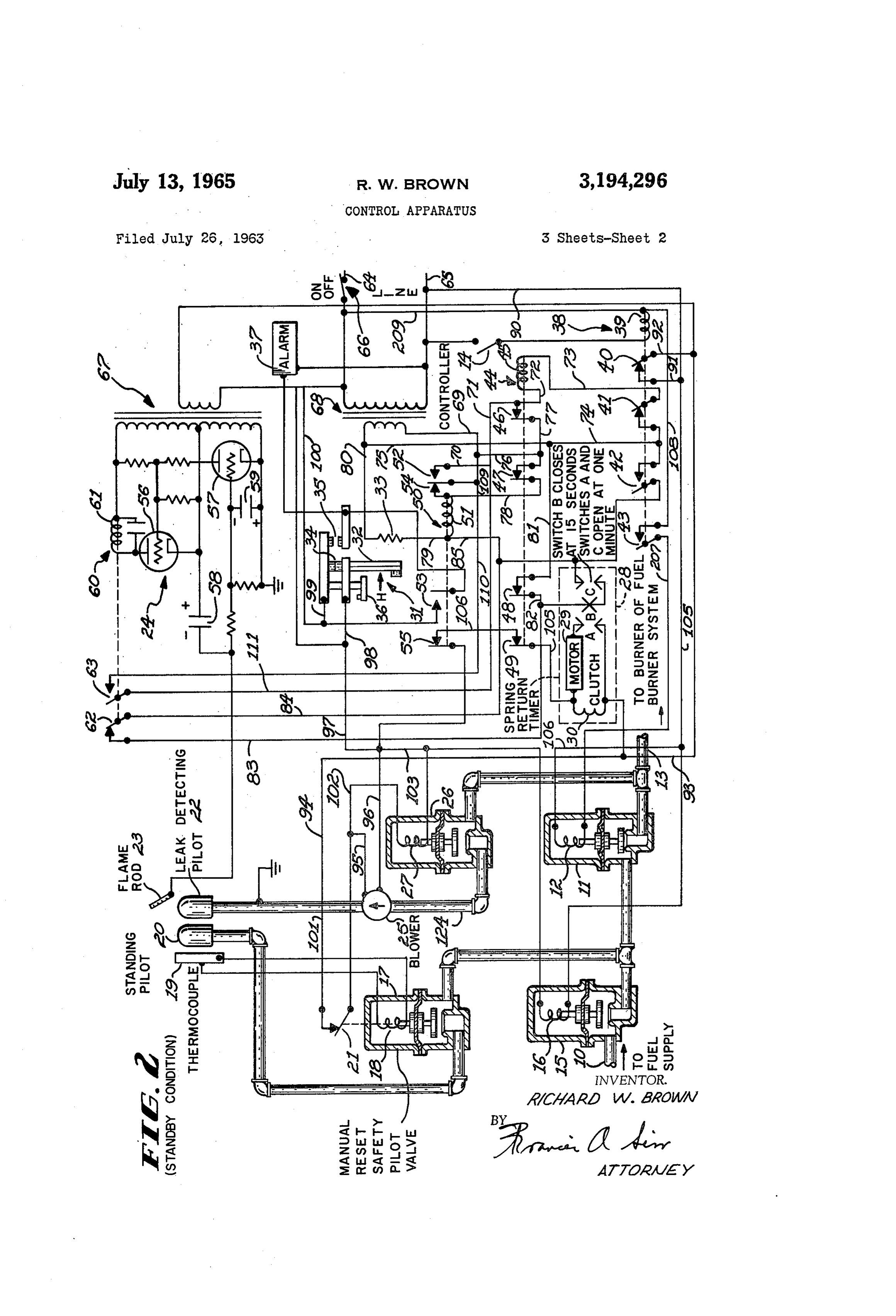
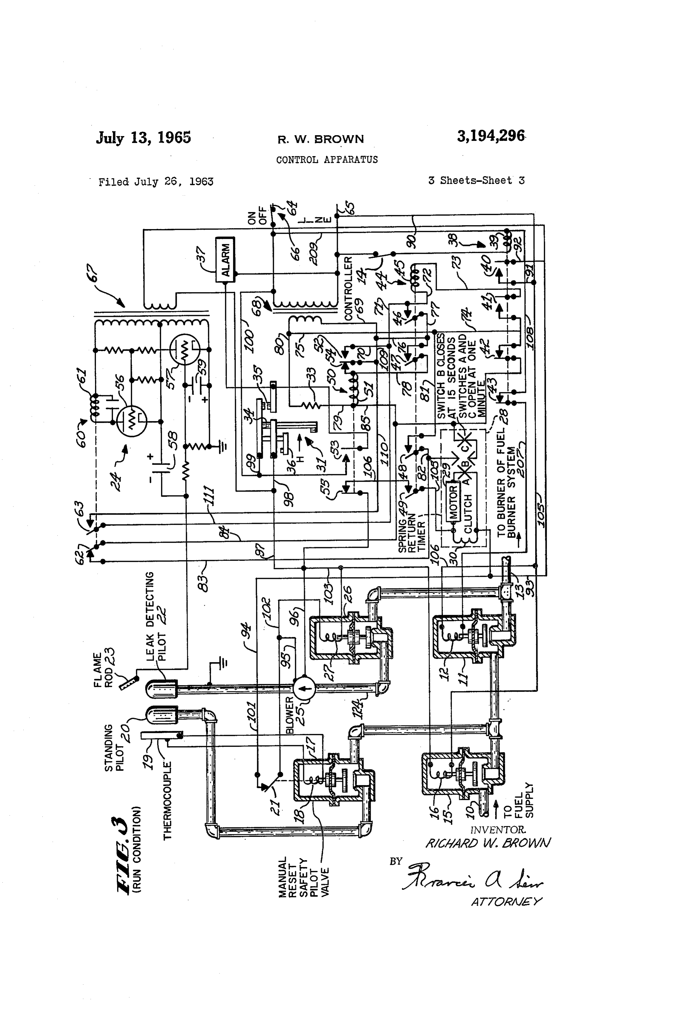
the fuel burner. This control may be derived either as FIGURE 1 is a showing of a preferred embodiment of a result of a predetermined process requirement or as a 20 my invention shown in the de-energized condition, result of the need for heat in an area to be maintained FIGURE 2 is the same embodiment shown in the in a given temperature by operation of the fuel burner standby condition, and installation. Combustion safeguard means are provided FIGURE 3 is the same embodiment shown in the run to supervise operation of the main burner, under the condition.
direct control of a main fuel valve which, when open, 25 Referring to FIGURE 1, reference numeral 69 desig allows fuel to flow from a main fuel supply pipe or con nates a fuel supply conduit which is connected to a duit to the main burner where it is then ignited by ignition source of fuel which is to be supplied to a fuel burner means, for example a pilot burner. During the standby installation, the components of which are not shown. period of operation, when heat is not required from the The flow of fuel to the fuel burner installation is fuel burner installation, the main valve is conditioned 30 under the control of a main supply valve 1, having a to be closed. Various failures may occur at this fuel winding 12 which, when energized, is effective to open the valve, such as Small particles of dirt lodging at the seat valve and to allow fuel to flow to a conduit 13 which of the valve, to result in a fuel leak. is connected to the burners of the fuel burner installation. The apparatus of my invention provides improved Energization of W1nding 12 of valve 11 is under the con control apparatus to detect such a fuel leak. I recognize 35 trol of a controller 14, shown as an open switch. that fuel leak detectors are generally old in the prior art. I have chosen not to show the components of the fuel However, prior art fuel leak detectors do not function burner installation, and the manner in which controller to provide the improved supervisory features which my 54 energizes these components since the exact manner invention incorporates. and structure to accomplish this may take many forms. Specifically, the structure of my invention provides an Controller 4 may in fact be pressure responsive or tem arrangement whereby a fuel valve leak detecting apparatus perature responsive, and may be an automatic actuator to includes a standing pilot which is associated with a thermo cycle the fuel burner installation automatically, to satisfy couple, a thermo-couple providing a safety pilot means a condition to which the controller is responsive. It to maintain flow of fuel to the standing pilot so long as suffices to say that there are many ways in which con flame is continuously detected at the standing pilot. Op 45 troller 4 may operate a fuel burner installation to es eratively associated with the standing pilot I provide a tablish flame at the burner installation. Furthermore, leak detecting pilot which is to be ignited by the standing combustion Safeguard apparatus may be provided, and pilot in the event a leak occurs. The leak detecting pilot is usually provided, to supervise the proper maintenance is connected at the end of a fuel flow circuit or pipe with 50 of flame at the fuel burner installation. a valve conditioned to be opened only when the thermo My invention is concerned with detecting a fuel leak couple Safety pilot detects flame at the standing pilot and at valve ii and it is intended that my invention be in only when the main fuel valve of the burner installation addition to the normal combustion safeguard devices pro is conditioned to be closed. Thus, I allow the leak de vided at a fuel burner installation. tecting pilot to be operative only if two conditions exist. Reference numeral 15 designates a safety valve having The first condition is that the standing pilot must be pres a winding 6. Safety valve 5 is connected in fuel-flow ent to ignite the leak detecting pilot in the event a leak series with valve A and, as will be apparent, safety valve occurs. The second condition is that the main fuel 5 is normally open and 1s closed only upon the detect valve must be conditioned to be closed. ing of a fuel leak, or upon a failure of a component of As a further feature of my invention I provide fame the fuel leak detecting system.
detecting means which is associated with the leak de 60 Reference numeral 17 designates a manual reset safety tecting pilot to detect flame only at this leak detecting pilot valve fromhaving a winding 18 which is connected to be pilot. Furthermore, I provide an arrangement whereby energized a thermo-couple 19 associated with a standing pilot burner 20. As will be apparent, not only proper operation of my improved apparatus requires that is valve 15 normally open, but valve 17 is also normally this flame detecting means detect the presence of residual 65 open fuel which is downstream of the main valve immediately to thusto maintain establish a standing pilot flame at pilot burner 20 thermo-couple 19 heated to hold valve subsequent to the closing of this main valve. 17 open and to maintain a switch 21 in a closed condition. In other words, it is recognized that a residual amount Valve 7 is of the general type in which means are pro of fuel will always remain at a position downstream of the vided to manually open the valve. However, switch 21 main valve immediately after the valve is conditioned 70 is closed, and valve 17 is maintained open only if thermo to be closed, and after it in fact does close. This residual couple 19 is heated.
fuel is supplied to the leak detecting pilot where a mo I have chosen first my apparatus in a de-energized con
Page 5drawing sheetscan →
Page 6scan →
99 and 100 to power line conductor 64. Thus, valve The apparatus is now in the run condition as shown 26 is conditioned to open and blower 25 is energized. in FIGURE 3 where valves 15 and 18 are open, valve 11 With both relays 44 and 50 energized, an energizing is open to allow fuel to flow to the fuel burner installa circuit is completed for timer 28. This energizing circuit tion, valve 26 is closed, blower 25 is deemergized, flame can be traced from power line conductor 65 through con 5 detector 24 is inoperative, timer 28 has reset so that ductors 90 and 91, switch 40, conductors 92, 93 and 164, Switches A and C are closed and switch B is open, relays clutch 30 and motor 29, conductor 105, switch 49, con 38 and 50 are energized, and relay 44 is de-energized. ductor 106, switch 55, conductors 107, 97 and , 98, switch This condition remains until the end of the period of 34, and conductors 99 and 100 to power line conductor need for operation of the associated fuel burner unit. 64. ? 0. At the end of a call for operation of the associated The energization of motor 29 and clutch 30 is effective fuel burner unit, as evidenced by the opening of con to cause rotation of the motor, and as indicated, switch B troller 14, relay 38 is again de-energized. The de-ener closes at 15 seconds after energization of motor 29 and gization of this relay connects the primary winding of clutch 30. Switches B and C, in series, form a circuit transformer 67 to power line conductors 64 and 65 to which shunts the closed switch 62 of flame relay 60 to 5 render the electronic flame detector 24 operative. allow frame relay 60 to respond to the residual fuel Furthermore, main valve 11 is closed and the fuel leak downstream of valve 11 immediately after the closing of detecting apparatus, including valve 26 and blower 25, is this valve without causing the energization of heater 33. actuated. At this time there is residual fuel in fuel At the one minute interval, switches A and C open. conduit 3 downstream of main valve 11. This residual The opening of switch C again places flame relay 60 in a 20 fuel produces a flame at leak detecting pilot 22. This condition to supervise energization of heater 33 of cutoff flame is detected by means 23-24 and as a result flame device 31 such that this heater is energized as flame is relay 60 is energized.
detected as a result of an actual fuel leak. The opening The energization of flame relay 60 causes switch 63 of switch. A de-energizes motor 29. The switches A, B to close. The closing of this switch is effective to com and C are maintained in their actuated positions by 25 plete an energizing circuit for relay 44. This energiz virtue of continued energization of clutch 30. Timer 28 ing circuit can be traced from the lower terminal of the is a spring return timer and subsequent de-energization secondary winding of transformer 68 through conductors of clutch 30 causes switches A, B and C to return to the 69, 109 and 110, switch 63, conductors 11, 71 and 72, position shown in FIGURE 1. winding 45, conductor 73, switch 41, and conductors 74 The apparatus is now in a standby condition as shown 30 and 75 to the upper terminal of this secondary winding. in FIGURE 2 wherein valves 15 and 17 are open, valve Thus, energization of relay 44 is evidence of the operabil 11 is closed, valve 26 is open, blower 25 is energized, ity of means 23-24 to detect the presence of flame. timer 28 is in its actuated position with switch A open, As soon as relay 44 is energized, the above traced ener switch B closed and switch C open, relay 38 is de-ener gizing circuit for motor 29 and clutch 30 of timer 28 is gized, and relays 44 and 50 are energized. 35 completed to institute a fuel burnoff period, but to institute The medium downstream of main valve i is drawn this period only if flame detecting means 23–24 has prov through open valve 26, by means of blower 25 and is pre en to be operative.
sented to leak detecting pilot 22. If this medium, or After a short interval of 15 seconds, switch B of the atmosphere, contains fuel, this fuel is ignited by standing timer closes to shunt heater 33 of safety cutoff means 31. pilot 20 and is detected as a fuel leak by flame detecting 40 In the event that flame detector 24 had failed and did not means which includes flame rod 23 and electronic flame detect the presence of flame which is known to exist as a detector 24. - - result of the residual fuel downstream of main valve 11, I will now describe the sequence of operation which heater 33 of safety cutoff means 31 would have remained takes place upon a need for operation of the associated energized and, after a time period of energization, safety fuel burner unit, as is evidenced by the closing of con 45 cutoff means 35 is actuated to open switch 34 and to close troller 14. The closing of this controller effects ener Switch 35. As has been mentioned, the opening of switch gization of winding 39 of relay 38, to actuate its asso 34 is effective to close valve E5 as an additional safety ciated switches. The opening of switch 40 is effective to feature and to energize alarm. 37.
de-energize the primary winding of transformer 67 asso Normally however flame detector 24 is operative and ciated with flame detector 24, this primary winding being as a result timer 28 is energized. However my apparatus connected to power line conductor 65 through switch 40. first checks the operability of the flame detector and insti The opening of switch 40 is also effective to de-energize tutes the residual fuel burnoff timing only after the flame winding 27 of valve 26, blower 25, and timer clutch 30. detector operability has been proven. Switch 42 shorts heater 33 of safety cutoff device 3 dur Timer 28 allows a one minute period for burnoff of the ing the run cycle of the associated fuel burner installa 55 residual fuel which is known to exist downstream of valve tion. The opening of switch 41 is effective to de-energize 11. After this one minute interval, switch C is opened winding 45 of relay 44. and heater 33 of safety cutoff means 31 is again placed The closing of switch 43 is effective to complete a under the Supervision of flame relay 60. In the event that energizing circuit for winding 12 of valve 1. This ener. valve if has failed to close, and that a leak thus exists at gizing circuit can be traced from power line conductor 60 the valve, leak detecting pilot 22 continues to sustain a 65 through conductors 90, 105 and 106 to winding 12, flame and flame relay 60 remains energized. So long as conductor 207, switch 43, and conductors 108 and 209 this relay remains energized, heater 33 of safety cutoff to power line conductor 64. Thus, valve is conditioned means 31 is also energized and after an additional time to open and fuel flows to the associated fuel burner unit. period (the timing period of means 31) valve 15 is closed The de-energization of relay 44, as a result of the 65 and alarm 37 is energized.
opening of switch 41, is effective to cause its switches Furthermore, if at any time during the standby period 46 and 47 to open. The opening of switch 46 opens the of the associated fuel burner installation (the period of above traced holding circuit for winding 45 of relay 44. which controller 14 is open) a fuel leak develops at valve 1, fame relay 60 is energized and heater 33 is then ener
The opening of switch 47 opens the circuit which pre viously shunted the closed switch 54 of relay 50 and thus 70 gized. After the timing period of safety cutoff means 31, relay 50 is maintained energized by way of a circuit which valve 15 will close and alarm 37 will be energized. includes only its closed switch 54. From the above description it can be seen that I have In the event of a power failure at this time, it is neces provided an improved control apparatus of a type to de sary that the starting cycle be repeated to energize relay tect a leak at a fuel valve, and that my apparatus is con 50. 75 structed and arranged to utilize a standing pilot such that
Page 7drawing sheetscan →
Page 8scan →
second flame sensing means responsive to flame at Said second pilot burner, timing means, checking means controlled by said second flame sensing means and operative upon the establishment of fame 5 at said second pilot burner due to the presence of residual fuel which exists at the position intermediate the fuel burner system, and the main fuel valve im mediately after the closing of the main fuel valve, means including said checking means to energize said timing means to begin a timing interval for burning off of the residual fuel upon operation of said check and safety means controlled by said second flame sens ing means and by said timing means and operative upon the presence of flame at said second pilot burn er after the expiration of said timing interval to pre vent fuel flow to said fuel burner system. 5. In combination:
a fuel burner unit having a main valve to control the 20 flow of fuel to a main burner, ? a controller operative to selectively control said main valve to be open or to be closed, a continuously burning first pilot burner having first flame detecting means associated therewith to main 25 tain fuel flow to said first pilot burner so long as flame is detected thereat, a second pilot burner, arranged to be ignited by said first pilot burner, having second flame detecting 30 means associated therewith to be responsive only to a flame at said second pilot burner, a fuel flow conduit connecting said second pilot burner to the downstream side of said main valve, said fuel flow conduit including means controlled by said con troller and by said first flame detecting means to al low said second pilot burner to sample for fuel at the downstream side of said main valve only when said main valve is controlled to be closed at a time when flame is detected at said first pilot burne time delayed safety cutout means having an actuator 40 and Switch means to be actuated after a time period of energization of said actuator, means to render said safety cutout means actuatorinop erative when said main valve is controlled to be open, a relay having a winding and switch means controlled thereby, checking means to check the operating of Said Second flame detecting means and including said relay winding to initially energize said relay winding when said main valve is initially controlled 50 to be closed and a flame detected at second pilot burner, means including said relay switch means to Subsequently maintain said relay winding energized so long as said main valve is controlled to be closed, a timer, including switch means, to time for a given interval the burnoff of residual fuel at the down stream side of said main valve subsequent to said main valve being controlled to be closed, means in cluding said relay Switch means to energize said timer upon energization of said relay winding, means including said timer switch means and said re 60 lay Switch means to render said safety cutout means actuator inoperative during said given interval, and means including said second flame detecting means to render said safety cutout means actuator opera 65 tive if flame is detected at said second pilot burner Subsequent to said given time interval.
6. Control apparatus for use with a fuel burner unit comprising:
a main burner, a main valve adapted to control the flow of fuel to said main burner, a controller operative to selectively control said main Valve to be open or closed, a continuously burning first pilot burner having first 75 flame detecting means associated therewith to main tain fuel flow to said first pilot burner so long as flame is detected thereat, a second pilot burner, arranged to be ignited by said first pilot burner, and having second flame detect ing means associated therewith to be responsive only to a flame at said second pilot burner, a fuel flow conduit adapted to connect said second pilot burner to the downstream side of the main valve, said fuel flow conduit including means adapted to be controlled by the controller and by said first flame detecting means to sample for fuel at the downstream side of the main valve only when the main valve is controlled to be closed at a time rwhen flame is detected at said first pilot burner, time delayed safety cutout means having an actuator and switch means to be actuated after a time period of energization of said actuator, a relay having a winding and switch means controlled thereby, checking means to check the operation of said second flame detecting means and including said relay winding to initially energize said relay winding when the main valve is initially controlled to be closed and the residual fuel downstream of the main valve causes a flame to be detected at said sec ond pilot burner, means including said relay switch means to subsequently maintain said relay winding energized, a timer, including switch means adapted to time for a given time interval the burnoff of the residual fuel at the downstream side of the main valve subse quent to the main valve being controlled to be closed, means including said relay switch means to energize said timer upon energization of said relay winding, means including said timer switch means and said re lay Switch means to render said safety cutout means actuator inoperative during said given time inter val, and means including said second flame detecting means to render said safety cutout means actuator opera tive if flame is detected at said second pilot burner Subsequent to said given time interval.
7. Control apparatus for use with a fuel burner unit mprising:
a main burner, a main valve adapted to control the flow of fuel to 'Said main burner, a controller operative to selectively control said main Valve to be open or closed, a continuously burning first pilot burner having first flame detecting means associated therewith, a Second pilot burner, arranged to be ignited by said first pilot burner, having second flame detecting means associated therewith and adapted to be re sponsive only to a flame at said second pilot burner, a fuel flow conduit adapted to connect said second pilot burner to the downstream side of the main valve, said fuel flow conduit including means adapted to be controlled by said controller and by said first flame detecting means to facilitate sampling for fuel at the downstream side of the main valve only when the main valve is controlled to be closed (at a time when flame is detected at said first pilot burner, time delayed safety cutout means having an actuator and switch means to be actuated after a time period of energization of said actuator, means to render said safety cutout means actuator in operative when said main valve is controlled to be Open, a first relay having a winding and switch means con trolled thereby, checking means to check the opera tion of said second flame detecting means and in cluding said first relay winding to initially energize 9 said first relay winding when the main valve is ini controller means operably connected to said fuel. tially controlled to be closed and a flame is detected burner unit, . . : ; at said second pilot burner as a result of residual a continuously burning pilot burner. and a first flame: fuel, means including said first relay switch means detector responsive to flame thereat, is ,"? , . . . . . . . ? to maintain said first relay winding energized when a 5 a second pilot burner arranged to be ignited by said: flame is thus detected, continuously burning pilotiburner and having a con a second relay having a winding and switch means. trollable fuel flow conduit; adapted to be connected. controlled thereby, means including said second re to a given portion of the fuel burner unit, lay winding and controlled by said first relay switch means controlled by said first flame detector and said means to initially energize said second relay wind controller means to sample for fuel at the given por ing upon energization of said first relay winding, tion of the fuelburner unit when, fuelis not inten--. .-- means including said second relay switch means to tionally being admitted thereto, | maintain said second relay winding energized, second flame detecting means responsive to flame: at . (means including said first relay winding and controlled. said second pilot burner, - . . . . |- by said second relay switch means to energize said and means controlled by said second flame detecting first relay, winding when the main valve is con means having a first check mode of operation re trolled to be closed and said second relay winding quiring the presence of flame at said second pilot. is deemergized, - - burner in response to a burnoff of residual fuel at: a timer, including switch means, adapted to time for a the given portion of the fuel burner unit as a result. given time interval the burnoff of residual fuel at the of said controller means initially interrupting opera. downstream side of the main valve subsequent to tion of the fuel burner unit, and having a second the main valve being controlled to be closed, means. leak detecting mode of operation requiring the ab-, including said first and second relay switch means sence of flame at said second-pilot burner after the to energize said timer upon energization of said first residual fuel is normally burned off."
means including said timer switch means and said first.
relay switch means to render said safety cutout
References Cited by the Examiner means actuator inoperative during said given time. UNITED STATES PATENTS 2,532,214:: -11/50 : Willenborg :--------- ------158-123 - .?
and means including said second flame detecting means 2,585,882 - 2/52, Weissman et al. i------158-122. to render said safety cutout means actuator operative : ?2,800 176 . . . . 7/57 - Morrison : ??????? ::125-158:'----. ? when flame is detected at said second pilot burner 2,839,129.6/58 St. Clair. 158 -122 ? Subsequent to said given time interval. 3,086,583. 4/63. Reichow .-- -------------------? 125—158 s 8. Control apparatus for use with a fuel burner unit to detect a fuel leak at a given portion of the fuel burner 35 FREDERICK L. MATTESON, Jr., Primary Examiner. unit, comprising:
a fuel burner unit, . - MEYER PERLIN, JAMES W. WESTHAVER, . . . Examiners,
Provenance
- Collection
- Patents citing this work
- Pages
- 9
- Method
- pdftotext (the PDF's own text layer) + pdftoppm 300dpi page scans
- Patent office record
- patents.google.com →
- Source
- Google Patents citing-documents table
- Assignee
- Honeywell Inc
- Published
- 1965-07-13
- Transcribed from
- patentimages.storage.googleapis.com →