

patent · US3219851A
Electrical energy conversion device
23 November 1965
Text
Drawings
Page 1drawing sheetscan →
Page 2drawing sheetscan →
Page 3drawing sheetscan →
Page 4scan →
United States Patent Office Patented Nov. 23, 1965 - 3,219,851
3,219,851 ternating current is fed to windings of the transformer to ELECTRICAL ENERGY CONVERSION OaWCE provide an alternating magnetic field which is displaced Robert P. Kidweli, 2213 Calle de Suenos, 90 in phase from the aforesaid electric field. A force is Las Cruces, N. Mex. developed within both dielectric or conductive materials in Filed May 17, 1961, Ser. No. 110,777 the conduit which force impels the same in a given direc 6 Claims. (C. 310-11) tion through the conduit. The pumping force is a func tion of the interaction between the electric and magnetic
The present invention relates to electrical devices for fields with charge-producing constituents of the pumped converting electrical energy at one frequency to direct Inedium. Dielectric materials, although poor conductors current and/or current at other frequencies and for con O of electricity, nevertheless have displacement currents or verting electrical to mechanical energy or mechanical to charges induced therein by the alternating fields to supply electrical energy. the condition for pumping action. Although crossed di Recently, researchers have expressed great interest in rect current magnetic and electric fields have the capabili the field of magnetohydrodynamics which involves the in ty of imparting forces upon ionized materials, it is not teraction of magnetic fields and electrically conducting 15 useful for pumping dielectric materials and is much less gases and other conducting fluids. Possible important ap Satisfactory than the orthogonally phased alternating cur plications of magnetohydrodynamics have been investi rent electric and magnetic fields of the present invention. gated in the fields of electrical power generation, ion ac If an ionized or otherwise conductive medium is caused celeration and propulsion systems. The present invention to move through the conduit in a direction opposite to the involves a unique application of magnetohydrodynamics 20 direction of the impelling force generated by the external involving electromagnetic fields interacting with conduc ly generated orthogonal electrical and magnetic fields, en tive mediums to provide efficient generation of electrical ergy is actually extracted from the flowing medium. Once power, and efficient conversion of electrical energy at one this extraction takes place, it is theoretically possible to frequency to alternating current of twice this frequency use the generated current to continue the initially ex an/or to direct current. Another important application 25 ternally generated electric and magnetic fields. of the invention is in the pumping of both dielectric and The medium acted upon by the cross alternating elec conductive materials by purely electromagnetic means. trical and magnetic fields of the present invention could In one application of the invention, electrical energy is also be a solid conductive body. It has been discovered extracted from flowing conductive gases by simple, rug that by anchoring such a conductive body to the walls ged apparatus with an exceedingly high conversion effi 30 of the aforesaid conduit in the region of the crossed elec (ciency. The main advantages of the invention lie in the tric and magnetic fields in a manner where the conductive high degree of flexibility, efficiency, simplicity, and rug body is insulated from the conductive walls of the conduit, gedness of the equipment constituting the present inven useful electrical energy can be obtained by coupling an tion. For example, electrical energy can be extracted output circuit across the ends of the conductive body. The from flowing streams of conductive gases at conversion 35 electrical energy comprises a direct current component efficiencies as high as 80-90%. and an alternating current component at twice the fre Pumping of dielectric and other fluids has heretofore quency of the alternating eelctric and magnetic fields. generally been carried out by purely mechanical means in Both the direct current and alternating current energy volving the direct contact of the fluid to be pumped with 40 components can be extracted from the output circuit by impeller blades and the like. Such pumping devices are suitable filters.
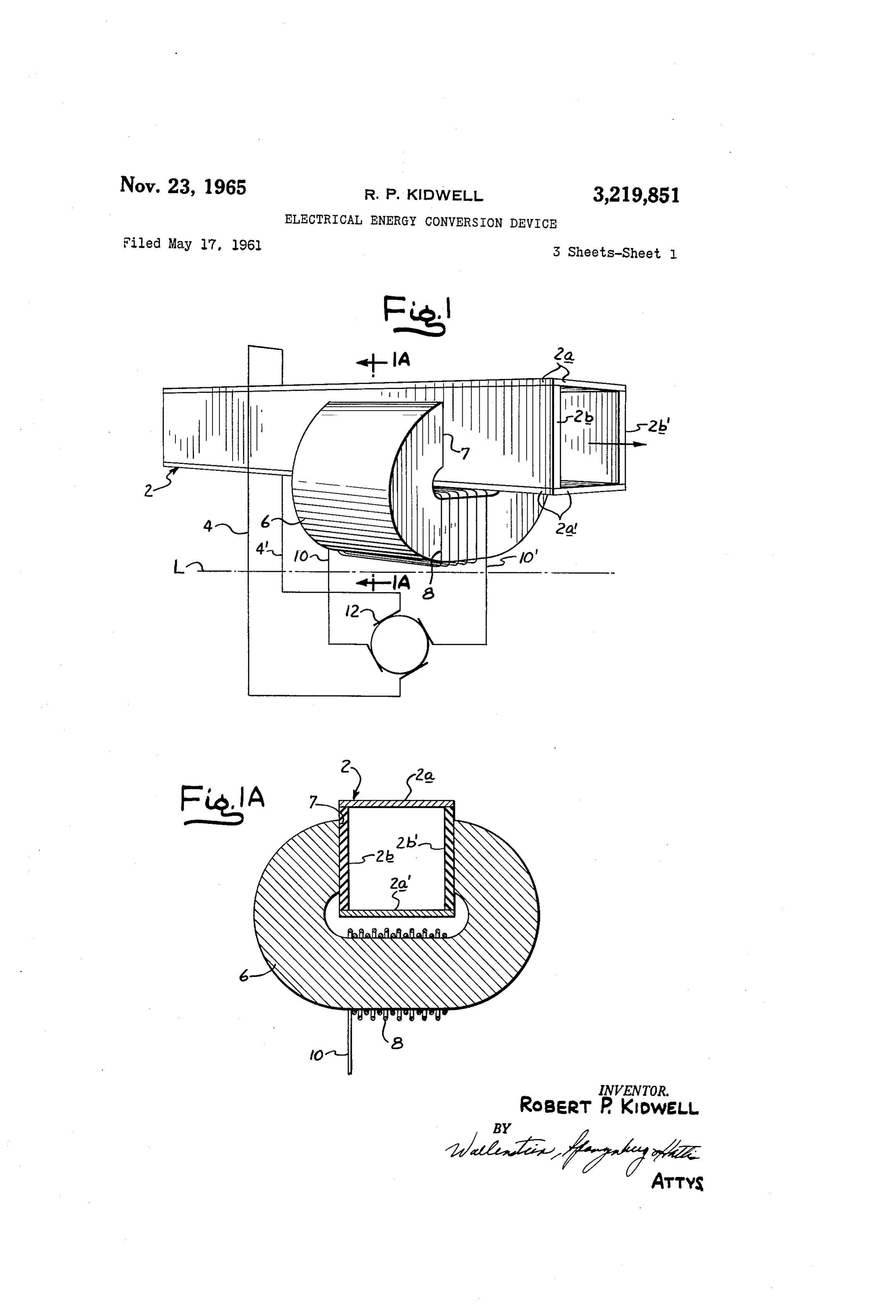
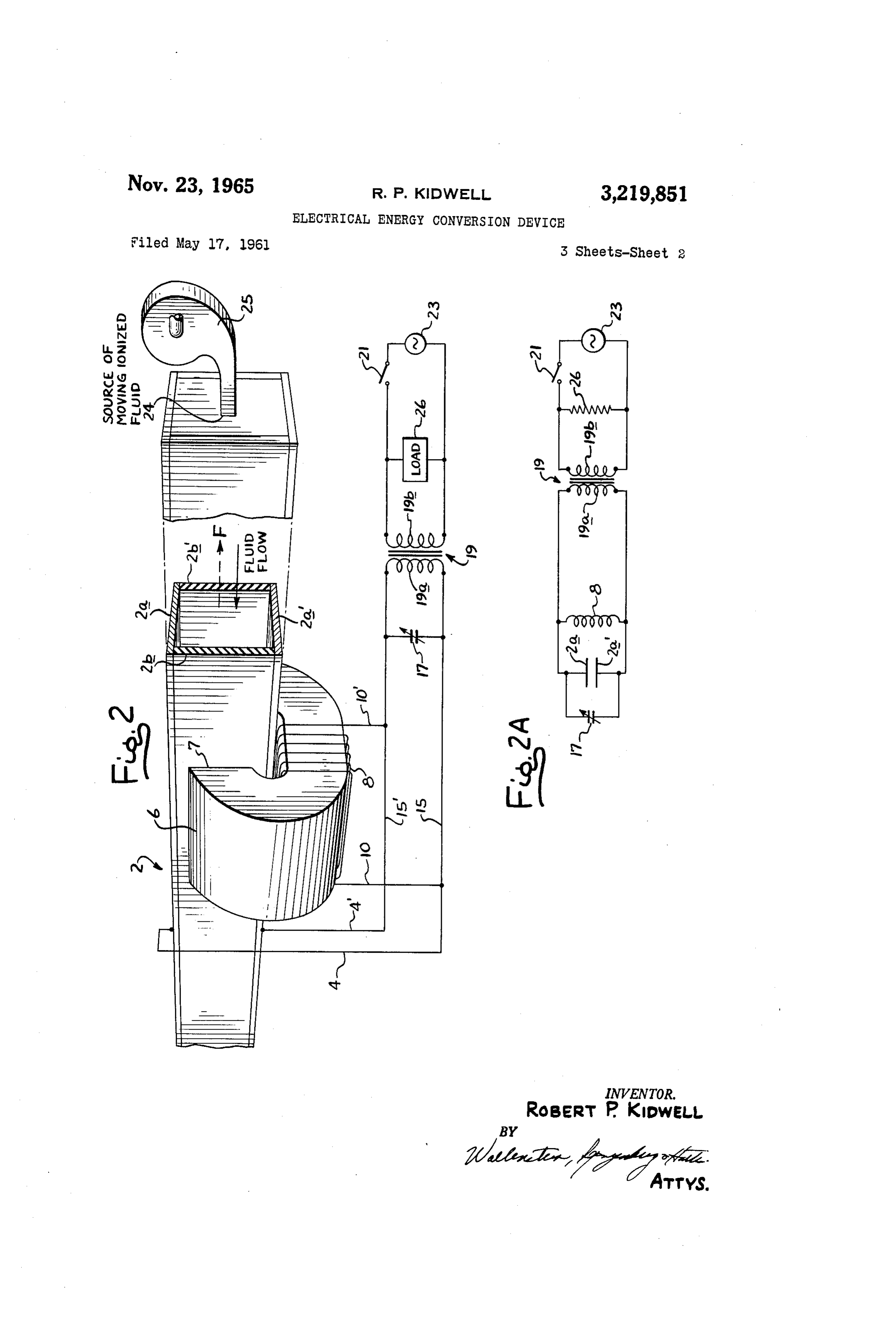
relatively inefficient and, in the case where highly cor Other advantages and features of the present invention rosive fluids are involved, require expensive and difficult will become apparent upon making reference to the spec to maintain pumping equipment. In contrast, the present ification to follow, the claims and the drawings wherein: invention effects an efficient pumping action by purely 45 FIG. 1 is a perspective view of the preferred form of electromagnetic means. the present invention applied as a pumping device; The various advantages broadly described above are FIG. 1A is a transverse section taken along section accomplished in the present invention through the inter line A-A in FIG. 1;
action of orthogonally related alternating magnetic and FIG. 2 is a view of the present invention applied as an electric fields operated at the same frequency and displaced 50 alternating current generator which extracts energy from in phase by approximately 90°. Although orthogonally a moving ionized fluid;
related magnetic and electric fields have been heretofore FIG. 2A is a simplified electrical diagram of the ap used in various ways for various applications, none have paratus shown in FIG. 2;
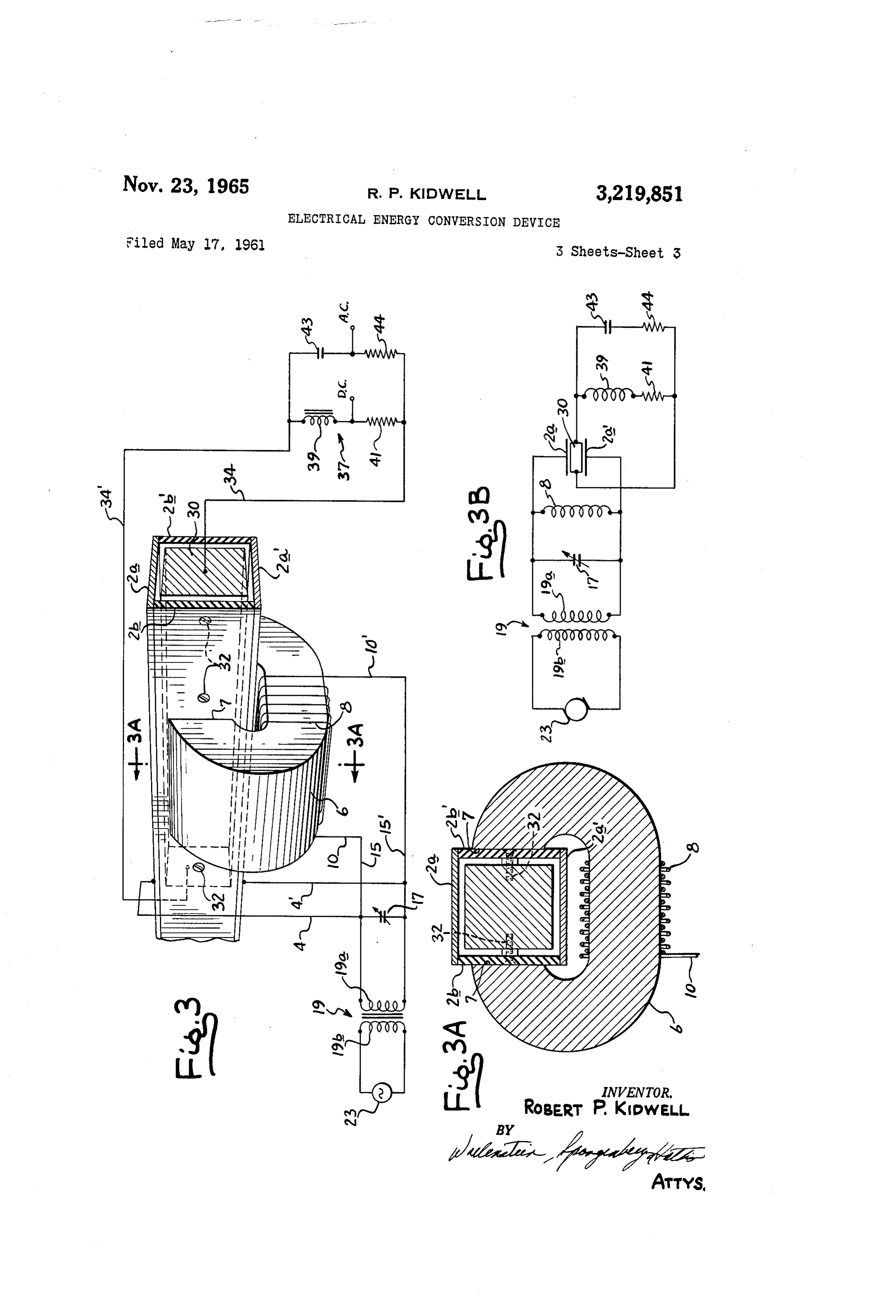
been alternating fields phased and used in the manner to FIG. 3 is an application of the present invention as a be described. device for converting an alternating current of a primary In accordance with the present invention, the cross elec 55 energizing voltage source to either direct current or al tric and magnetic fields are caused to interact with var ternating current at twice the frequency of the energizing ious media in different ways, depending upon the applica voltage;
tion invloved. Thus, when the invention is applied as a FIG. 3A is a transverse section of FIG. 3 taken along pump, the aforesaid electric and magnetic fields are ex 60 Section line 3A-3A therealong; and ternally generated and applied to a conduit carrying the FIG. 3B is a simplified electrical diagram of the ap fluid to be pumped. In the most preferred form of the paratus of FIG, 3.
present invention, the conduit comprises a pair of opposed Referring now and more particularly to FIGS. 1 and conductive walls forming a pair of electric field developing 1A, that portion of the apparatus shown above the dot electrodes and joined by a pair of insulating walls. An al 65 ited line L represents a preferred form of electromagnetic ternating current electric field is developed between the apparatus which is applicable to all of the aforementioned conductive walls forming a pair of electric field developing applications of the invention. The connections and com voltage thereto at a given frequency. The magnetic field ponents shown below the dotted line L are used to operate is generated within the conduit at right angles to the elec the apparatus shown as a device for pumping dielectric tric field by placing the conduit in an air gap of a C 70 or conductive fluids. The apparatus there shown includes shaped core of magnetic material forming the core of a a conduit generally indicated by reference numeral 2 transformer. In a preferred manner to be described, al having upper and lower conductive walls 2a-2a' made 5 of metal or other suitable material and spaced insulat tric fields will act upon the ionized medium in the con ing side walls 2b-2b' bridging the corresponding longi duit 2 in the direction indicated by the vector F in FIG. 2. tudinal marginal portions of the conductive walls 2a and FIG. 2 shows an apparatus similar to that shown in 2a'. Conduit 2 forms a fluid-tight passageway which in FIG. 1 but including a source 24 of a moving ionized terconnects the supply of the fluid to be pumped with the fluid, which source appears at the output of a fan device point at which the fluid is to be carried. A pair of 25. It is apparent that this source of moving ionized conductors 4-4 are respectively connected to the conduc gas or other fluid can be the byproduct of an industrial tive walls 2a and 2a' of the conduit. process or the like. In accordance with the invention, The conduit 2 is placed in the air gap 7 of a C-shaped the source of ionized fluid is caused to flow through the core 6 of magnetic material. The spaced confronting 0. conduit 2 in a direction opposite to the direction of the surfaces of the core 6 defining the margins of the air gap force Vector F. In such case, energy will be extracted engage or are contiguous to the insulating side walls 2b from this ionized fluid by the electromagnetic device of 2b' of the conduit 2. Windings 8 are wound around the the present invention. The energy so extracted will ap core and the ends of the windings are connected to con pear across a load 26 at the frequency to which the cir ductors 0-10'. cuit is tuned by the tuning capacitor 17. For practical In the various forms of the invention to be described, reasons, this frequency would be the frequency of the alternating voltages of proper phase appear on or are fed output of generator 23. Once the system begins generat to the conductors 4-4' and 10-10' leading to the con ing power, the switch 21 could theoretically be opened ductive walls 2a-2a' and windings 8 in different ways to since the extracted power could maintain the electric and produce orthogonally phase crossed electric and magnetic 20 magnetic fields referred to.
fields. In each instance voltages are either externally or Referring now to the embodiment of the invention internally generated to produce an alternating electric shown in FIGS. 3 and 3A which is a system for convert field extending between the conductive walls 2a-2a' and ing alternating current to direct current and an alternat an alternating magnetic field at right angles to the elec ing current at twice the frequency of the alternating cur tric field. The phase of the magnetic field lags or leads 25 rent. The source of alternating current is the generator the phase of the alternating electric field by about 90 23 coupled through the primary and secondary winding so that the two fields are orthogonally related in both a of the transformer 19 to a resonant input circuit which is physical as well as a time sense. In the pump applica identical to the corresponding portion of the circuit tion of the invention shown in FIG. 1, the conductors shown in FIG. 2A. The corresponding parts of these 4-4' and 10-10' lead to the terminals of a voltage gen 30 two circuits have been similarly numbered, as are the erator 12 which apply voltages of the proper phase to corresponding parts of the apparatus producing the or produce the aforementioned electric and magnetic fields. thogonal electric and magnetic fields in the conduit 2. As an illustrative example of the invention, the voltage Aside from the omission of the on-off switch 21 and the applied across the plate 2a and 2a" may be 100 volts rms. load impedance 26 shown in FIG. 2, the only other dif and the magnetic field may be 1000 gauss rms. As previ ference in the apparatus of FIG. 3 is the conductive me ously indicated, the fluid pumped by the device illustrated dium which is located within the conduit 2 and the elec in FIG. 1 is most desirably a gaseous or liquid fluid but trical circuitry associated therewith. The conductive me it may also be a solid material provided the solid mate dium in this form of the invention is a conductive metal rial is kept from short circuiting the conductive walls 40 bar 30 which is fixedly mounted within the conduit by 2b-2b. It is apparent also that the fluid to be pumped means of screws 32 passing through the insulating walls must not be so highly ionized as to represent a short cir 2b and 2b'. The conductive body 30 is spaced from the cuit path for current flow between the plates 2a and 2a'. conductive plates 2a and 2a' so as to be insulated there The resulting interaction between the orthogonally related from. A pair of conductors 34-34 are soldered or oth electric and magnetic fields is to provide an extremely ef erwise electrically connected to the opposite ends of the ficient pumping device which uses little or no power except conductive bar 30. These conductors extend to an out when it is effective to pump fluid through the conduit. put circuit generally indicated by reference numeral 37. When there is no fluid to pump, the apparatus is in an The output circuit 37 shown comprises a first branch in idle state which uses very little power in comparison with cluding an A.C. filter choke 39 in series with a load re mechanical pumping devices which must impart movement sistor 41. The other branch comprises a D.C. filter ca to impeller blades and the like even during an idling 50 pacitor 43 in series with a load resistor 44. period. The operation of the apparatus shown in FIG. 3 is as Referring now to the form of the invention shown in follows: The generator 23 and the associated resonant FIG. 2 which is an alternating current generator which circuitry provide crossed orthogonally phased and related extracts energy from a flowing ionized fluid. The corre electric and magnetic fields in the manner described in sponding parts of the apparatus shown in FIG. 1 and 55 connection with the embodiment of FIG. 2A where the FIG. 2 have been similarly numbered. In FIG. 2, the generator 23 initially provides these fields. Since the con conductors 4-4' and 10-10' extending to the conductive ductive body 30 is permanently anchored to the conduit, walls 2a and 2a' of the conduit 2 and the windings 8 re it does not use any of the generated energy. However, spectively extend to a pair of common conductors 15-15'. it can be shown that electrical signals are induced within The conductive walls 2a and 2a", in effect, form the plates 60 the conductive bar 30 which have both direct current and of a capacitor which are coupled in parallel to the wind double frequency signal components. These two compo ings 8 which constitute an inductance coil. A tuning nents can be separated out by means of the output cir capacitor 17 is connected between the conductors 15 and cuit 37. The filter choke 39 filters out the alternating cur 15” for tuning the parallel circuit to resonance. rent component from this branch circuit so that substan The conductors 15-15 extend to opposite ends of a 65 tially pure direct current voltage appears across the load secondary winding 19a of a transformer 19. The primary resistor 4i. In the other branch circuit, the capacitor 43 winding 19b of the transformer 19 is coupled through filters out any direct current component from the load an on-off switch 2 to a generator 23 which generates a resistor 44 so that a double frequency signal component voltage at a frequency to which the aforesaid circuit is appears across the resistor 44. Obviously one or both of tuned. When the switch 21 is closed, it will be seen that 70 these branches may be utilized depending upon whether a voltage will be applied to the conductive walls 2a and D.C. or A.C. or both of the signal components are de 2a' of conduit 2 which is 90° out of phase with the cur sired.
rent flowing in the inductance coil 8, which produces a It should be understood that numerous modifications magnetic field in phase with this current. The force which is generated by the interaction of the magnetic and elec may be made of the preferred forms of the invention de 6 scribed above without deviating from the broader aspects ionized fluid under pressure, means connecting said source of the invention. of ionized fluid to said conduit to cause the same to flow What I claim as new and desire to protect by Letters through the conduit in a direction opposite to the impel Patent of the United States is: ling force developed in the electric and magnetic fields 1. An electromagnetic electricity generating device com 5 respectively developed between said electrodes and in said prising: a conduit for an ionized fluid, said conduit in coil, and output means for extracting energy from said cluding a first pair of insulated electrodes on opposite parallel resonant circuit induced in part therein by the sides of the conduit, electromagnet means including a flow of ionized fluid through said conduit. coil for providing a magnetic field in the space between 5. An electrical generator device comprising: a conduit said electrodes and extending in a direction generally at O in which an ionized fluid may flow, said conduit includ right angles to a line extending between said electrodes, ing a first pair of spaced insulated electrodes on opposite and circuit means including means connecting said elec sides of said conduit, inductive means comprising a coil trodes and coil together to form a circuit which is reso arranged to direct its magnetic field within said conduit nant at a desired frequency of extraction of energy from in the space between said electrodes and in a direction said ionized fluid. generally at right angles to a line extending between said 2. An electromagnetic transformer for extracting en electrodes, means connecting said electrodes and said coil ergy from a flowing ionized fluid comprising: a conduit in parallel circuit relation to form part of a parallel res in which said fluid flows, said conduit including a first onant circuit, tuning means for tuning the parallel res pair of spaced insulated electrodes on opposite sides there onant circuit to a given frequency, alternating current of, inductance means comprising a coil which when cur 20 generator means providing an output at said given fre rent flows therein provides a magnetic field in the region quency and coupled in parallel with said parallel reso between said electrodes at right angles to a line extend nant circuit, a source of ionized fluid under pressure, ing between said electrodes, means connected to said elec means connecting said source of ionized fluid to said con trodes and said coil for providing a magnetic field in the duit to cause the same to flow through the conduit in a space between said electrodes which is displaced 90 in 25 direction opposite to the impelling force developed by the time from an orthogonal electric field extending between electric and magnetic fields respectively developed be said electrodes, said magnetic and electric fields provid tween said electrodes and in said coil, and output means ing a force capable of impelling fluid in a given direction for extracting energy from said parallel resonant circuit in said conduit, means for forcing ionized fluid through induced in part therein by the flow of ionized fluid through said conduit in a direction opposite to said given direc 30 said conduit.
tion, and means including tuning means connected to said 6. An electromagnetic pumping device comprising: a electrodes and said coil for forming a tunable resonant conduit in which an operating medium is to be located circuit. and including a first pair of insulated conductive elec 3. An electromagnetic transformer for extracting en trodes on opposite sides of the conduit, electromagnet ergy from a flowing ionized fluid comprising: a conduit means including a coil for providing a magnetic field in in which said fluid flows, said conduit including a first the space between said electrodes and extending in a di pair of spaced insulated electrodes on opposite sides there rection generally at right angles to the line extending be of, inductance means comprising a coil which when cur tween said electrodes, circuit means including means con rent flows therein provides a magnetic field in the region necting said electrodes and coil together to form a par between said electrodes at right angles to a line extend 40 allel resonant circuit, and energizing voltage means con ing between said electrodes, means connected to said elec nected to said parallel resonant circuit at the frequency trodes and said coil for providing a magnetic field in the to which the resonant circuit is tuned, whereby the or space between said electrodes which is displaced 90 in thogonal electric and magnetic fields alternate 90 out of time from an orthogonal electric field extending between 45 phase with one another.
said electrodes, said magnetic and electric fields provid ing a force capable of impelling fluid in a given direction References Cited by the Examiner in said conduit, and means for forcing ionized fluid through UNITED STATES PATENTS said conduit in a direction opposite to said given direc 1,736,643 11/1929 Beck.
tion.
4. An electrical generator device comprising: a con 50 2,391,801 12/1945 Schade ------------- 307-151 duit in which an ionized fluid may flow, said conduit in 2,434,705 1/1948 Lago.
cluding a first pair of spaced insulated electrodes on op 2,715,190 8/1955 Brill ---------------- 310-11 posite sides of said conduit, inductive means comprising 2,787,219 4/1957 Werner --------------- 103-1 a coil arranged to direct its magnetic field within said 3,002,383 10/1961 Mittelmann ---------- 73-194 conduit in the space between said electrodes and in a di 5 5 3,034,002 rection generally at right angles to a line extending be 5/1962 Carlson -------------- 310-11 tween said electrodes, means connecting said electrodes ORIS L. RADER, Primary Examiner.
and said coil in parallel circuit relation to form part of a parallel resonant circuit, tuning means for tuning the MILTON O. HIRSHFIELD, Examiner.
parallel resonant circuit to a given frequency, a source of 60
Provenance
- Collection
- Patents citing this work
- Pages
- 6
- Method
- pdftotext (the PDF's own text layer) + pdftoppm 300dpi page scans
- Patent office record
- patents.google.com →
- Source
- Google Patents citing-documents table
- Assignee
- Robert P Kidwell
- Published
- 1965-11-23
- Transcribed from
- patentimages.storage.googleapis.com →