

patent · US3225816A
Safety device for gas fired boilers
28 December 1965
Text
Drawings
Page 1drawing sheetscan →
Page 2scan →
United States Patent Office 3,225,816 Patented Dec. 28, 1965
The igniter 10' and the fan motor 25 are also shown 3,225,816 connected in parallel to wires 23 and 24.
SAFETY DEVICE FOR GAS FREED BOLERS Thus, valve 12 is represented as normally closed and George H. Familo, Oswego, N.Y., assignor of fifty percent is opened by energizing its solenoid through the energiz to Harvey J. Tucker, Syracuse, N.Y.
Filed Aug. 10, 1962, Ser. No. 216,198 ing of relay 4 when the thermostatic switch 13 is closed 11. Claims. (C. 158-25) by reason of the dropping of temperature in boiler B. With the opening of valve 12, igniter 10' is energized
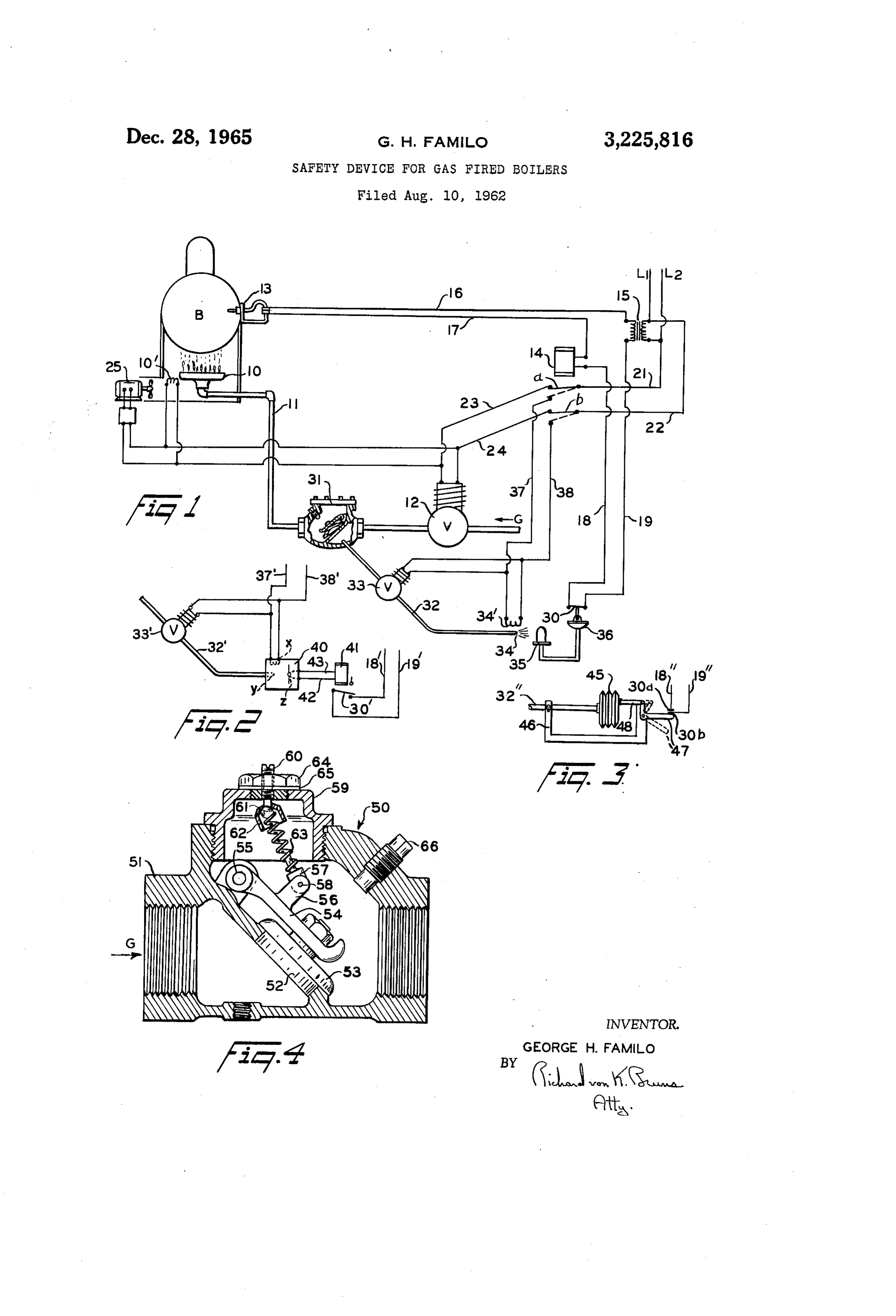
This invention relates to a safety device for gas-fired and burner 10 is ignited to heat the boiler. When the boilers. More particularly, it relates to a device for desired degree of heat in the boiler is again reached preventing explosions in a boiler combustion chamber O Switch 3 opens and blades a and b of the relay return in which the burner is alternately ignited and turned off to "open' position, indicated by broken lines, and solenoid automatically in response to thermosensitive controls. 2 is deemergized and the valve again closes. One well-known type of gas fired boiler employs a Many other arrangements of parts and electrical cir remotely controlled shut-off valve for turning the gas cuits for obtaining the same results may be devised. Supply to the burner on and off in response to a thermally 5 Timing and time-delay devices may be employed and a Sensitive control located at the boiler. To conserve pilot flame may be advantageously used in conjunction heat the burner is in a closely confined combustion with the igniter 10'. Means to disconnect the igniter 10' chamber which is provided with air by means of a fan after the burner 10 is lit are frequently provided, but only while the burner is lit. Frequently the shut-off nine of these devices are shown in the interest of clarity. Vaive develops a leak after extended use and gas seeps 20 The danger, which it is the object of the present inven by the valve into the combustion chamber and causes an tion to eliminate, is that, if valve 12 should leak during explosion when the shut-off valve is again turned on and periods when the burner is not lit, gas flows through the the burner ignited. line 1 to the burner 10 and remains in the combustion The principal object of the present invention, accord chamber because the fan motor 25 is turned off. When ingly, is to provide means for sensing the presence of gas 25 igniter 0' is subsequently energized an explosion follows. downstream of the shut-off valve when the valve is closed. To eliminate this danger, a normally closed safety Another important object is to prevent the re-ignition switch 30 is inserted in the control circuit between wires of the burner once the flow of gas past the closed shut-off 18 and 19. A pressure sensitive valve 31, shown as an valve is sensed. ordinary gravity biased gate check valve, is also provided Still another object is to provide automatically operat 30 in the gas supply line between valve 12 and burner 10. ing safety means to detect the presence of gas downstream A bleed line 32 is led off from line 11 between valves of the shut-off valve when the valve is closed and to 12 and 3 and another solenoid operated shut-off valve automatically prevent the re-ignition of the gas burner 33, is provided in the bleed line. The bleed line may, Subsequent to the detection of gas. for convenience, be led off from the “up stream” side of Further objects and advantages will become apparent 35 valve 3 as shown.
from the following description taken in conjunction with At the other end of bleed line 32 a jet is provided the accompanying drawing in which: to form a pilot burner 34 and an electrically operated FIGURE 1 is a semi-diagrammatic showing of one igniter 34' is provided to light burner 34 if any gas escapes form of the invention applied to a gas fired boiler; through line 32.
FIGURES 2 and 3 are fragmentary semi-diagram 40 A thermal sensing device is provided in heat associa tmatic showings of modified forms of the invention; and tion with the pilot burner 34 to open the switch 30 if gas FIGURE 4 is an enlarged longitudinal sectional view should leak past the valve 12 when it is closed. A of a modified form of check valve. thermostatic device is shown at 35 in FIGURE 1 having Referring more particularly to FIGURE 1, a gas fired a diaphragm or other movable part 36 linked to the switch boiler B is shown having a burner 10 to which gas is 45 30 for opening the switch when the heat sensing bulb of conducted by the gas line 11. Gas supply line 11 is the device is heated.
provided with a solenoid operated shut-off valve 2 and The valve 33 and igniter 34' are connected by wires 37 an electrically operated igniter 10' is provided adjacent and 38 to the “open' contacts of the blades a and b of burner 10 to light the burner when valve 2 is first the relay 14. When the blades a and b are in their opened. 50 “open' position, a connection is made through wires 21 A thermostatic or thermo-electric device 13 is provided and 22 to the source of current to open the valve and at boiler B and it will be understood that the heat sensing power the igniter.
portion of device 13 operates to open a normally closed The operation of the invention is as follows: During Switch in the device when the boiler has reached the the normal operation of the boiler, burner 10 continues selected temperature. 55 to burn so long as valve 2 is open. So long as valve 12 Automatic controls represented by a relay 14 are pro is When open the valve 33 remains closed. the thermally operated switch 13 opens because vided for operating valve 12 as demands for heat are of sufficient heat in the boiler, the control circuit to relay signalled by the device 3. A transformer 15, connected A4 is thereby broken and the relay is deemergized. to a source of electric current L1, L2, is provided for operation of relay 4 since it is usually advantageous to 60 Blades a and b are released from their normal operating position with “closed” contacts thereby cutting off cur run Such a control circuit at less than line voltage. One rent to the valve 12 which reverts to its closed position. control terminal of relay 14 is connected through the At the same time, blades a and b having returned to Switch of device 13 to one pole of the transformer 15 by wires 16 and 17. Wires 18 and 9 normally connect 65 their “open’ position shown in broken lines in FIGURE 1, current is supplied to the solenoid of valve 33 to open the other control terminal of relay 14 to the other pole this valve. Current is also supplied to the igniter 34 so of the transformer. long as blades a and b remain in the “open' position. The switch mechanism of relay 4, shown in FIGURE Valve 31 is open when gas under normal line pressure 1 in its normal operating position represented by blades passes through line 1 to the burner 0, but when the a and b are adapted to open valve 12 by connecting its 70 valve 2 is closed the valve 31 is biased to close. How solenoid to L1 and L2 through the wires 23 and 24, the ever, any gas which leaks past valve 12, when it is closed, "closed” contacts of blades a and b, and wires 21 and 22. is at a substantially lower pressure than normal. Valve
Page 3scan →
3 is gravity biased to remain closed at such lower pres While the location of the safety switch in the control sure and leaked gas is therefore by-passed through the circuit for relay 4 is preferred in order to make the bleed line 32 to burner 34. At the burner any gas thus safety device automatic, it will be understood that the by-passed is ignited by the activated igniter 34. gas sensing devices shown in FIGURES 1-3 can also The bulb of the thermosensitive device 35, when heated be used to operate a warning signal, to turn on the fan by the flame at burner 34, operates in the usual manner motor 25, or to operate other devices for preventing Sub through its capillary tube and moves the diaphragm 36 sequent re-ignition of the burner 0. to open the safety switch 30. Accordingly, when the As will be apparent to those familiar with the art, the temperature in the boiler next falls and the Sensing invention may be embodied in other specific forms with device 3 operates to connect wires 16 and 17, the relay O out departing from the spirit or essential characteristics 14 is not energized because switch 30 remains open as thereof. The embodiments disclosed are therefore to long as there is a flame at burner 34. be considered in all respects as illustrative rather than Although the thermal sensing device 35-36 is rep restrictive, the scope of the invention being indicated by resented as a vapor pressure operated device it will be the appended claims.
apparent that any other known type of thermal sensing 15 What is claimed is:
device may be used to operate the safety switch 30. E. A safety device for signalling a leak past an auto In FIGURE 2 a commercially available switch operat matically operated supply valve in a line for Supplying ing device is represented at 40 connected to bleed line 32 gas at a normal pressure, comprising: a pressure Sensi and wires 37' and 38. The box 40 represents a unitary tive valve in the supply line downstream from the Supply gas sensing device manufactured by Mine Safety Appli 20 valve, said pressure sensitive valve having a gate that ance Co. of Mountainside, N. J., catalogue No. 16,386. opens under normal gas pressure in the line and is biased The device 40 is provided with an igniter x and burner y toward closed position at less than normal gas preSSure, which, when ignited, operates a thermoelectric generator a bleed line connected in the supply line between Said g to energize relay 4 through the wires 42 and 43 and supply valve and said biased gate, automatically oper open switch 30' in the control circuit between wires 18' 25 ated valve means in said bleed line, means for closing and 9'. said last-named valve when the supply valve is open and In FIGURE 3 a pressure operated gas sensing device opening said last-named valve when the supply valve is is represented. Bleed line 32' is connected to a bellows closed, and means at the end of the bleed line for Sensing 45 and supported on a frame member 46. The bellows the presence of gas escaping therefrom whereby a leak 45 is connected to a lever 47 by a link 48, and the lever 30 in the supply valve can be detected. carries one contact 30b of a safety switch between wires 2. A safety device for a heating system using Com 18’ and 19'. Lever 47 is pivotally mounted on mem bustible gas under a substantially constant normal prest ber 46 and the other safety switch contact 30a is carried sure, which system includes an automatically operated on a fixed arm, not shown, supported by member 46. supply valve for internittently shutting off and turning When gas leaks past the valve 12, it is by-passed 35 on the flow of gas in a gas supply line according to the through the bleed line 32' by the pressure-sensitive valve demands of the system, and including means for igniting 31. Bellows 45 is adapted to expand at a pressure less the gas when the supply valve is turned on, comprising: than the bias with which valve 31 is closed, so that the a pressure sensitive valve in the Supply line downstream bellows expands and breaks the electrical connection be from the supply valve, said pressure sensitive valve hav tween contacts 30a and 30b when any appreciable amount 40 ing a gate that opens under normal pressure in the line of gas leaks past the valve 2. and is biased toward closed position at less than normal In FIGURE 4, a pressure sensitive valve 50 is shown pressure in the line, a bleed line connected in the Supply in which the bias closing the valve at less than normal line between said supply valve and said biased gate, auto gas-line pressure is adjustable. matically operated valve means in said bleed line, Said The direction of flow of gas through supply line 11 is last named valve means being closed when the supply indicated by the arrow G through the body 51 of valve valve is open and open when the Supply valve is closed, 50. A port 52 in the valve seat is closed by a valve and means at the end of the bleed line for sensing the 53 which is carried on a gate arm 54 hingedly Secured escape of gas from the end of the bleed line, said Sen at 55 within the body 51. Gate arm 54 is provided with sing means being operably connected in the System for two upwardly projecting lugs 56 between which a Spring 50 automatically preventing the operation of the ignition carrier 57 is hingedly secured by a pivot pin 58. The means following a period in which the Supply valve is usual cap 59 of valve 50 is provided with an adjustment turned off and the presence of gas is detected by Said screw 60 threaded therethrough. The lower end of Sensing means.
screw 60 is provided with a spherical projection or ball 3. A safety device for employment in a system using 61 and a spring retaining cap 62 is clinched about the ball 55 combustible gas under pressure, which system includes so as to swivel thereon. an automatically operated valve for intermittently shut One end of an extension coil spring 63 is engaged by ting off and turning on the flow of gas in a gas Supply the rod-like end of carrier 57 and the other end of the line to a combustion chamber and re-igniting the re spring engages ball 61 within cap 62. A nut 64 and sumed flow of gas according to the demands of the Sys sealing washer 65 are provided for sealing the adjustment tem, comprising: a pressure operated valve in the gas screw in cap 59. The usual pipe plug 66 is provided as 60 supply line between said automatically operated valve a bumper for the turned-up end of gate arm 54. and said combustion chamber; said pressure operated Nut 64 may be loosened and screw 60 advanced within valve having a gate that opens at normal pressure in the cap 59 to increase the compressive tension on Spring the line and is biased to a closed position when there 63 for increasing the closing bias on valve 53 or Screw 65 is less than normal pressure in the line; a bleed line 64 may be backed off to decrease the bias. connected at one end to said supply line between the While the normal gas pressure in the Supply line 11 automatically operated valve and the pressure operated is not great, it will be apparent that spring 63 may be valve; an automatically operated valve in Said bleed line dimensioned and screw 60 adjusted to operate at any adapted to close when the shut off valve in the supply selected pressure less than normal gas pressure without 70 line is open and to open when the shut off valve is closed; impeding the flow of gas to burner 10 when valve 12 means at the other end of said bleed line for detecting is open, and to keep valve 53 closed so as to by-pass all the flow of gas through said bleed line; and means op gas leaking by valve 2 when the latter is closed. This erable by Said gas detecting means for preventing the valve is especially useful in the modified form of the Subsequent re-ignition of said gas in the combustion invention shown in FIGURE 3. 75 chamber.
Page 4scan →
4. A safety device for employment in a system using comprise: a pilot burner at the end of the bleed line, an gas under a normal pressure, which system includes a electrically operated igniting device for lighting said pilot gas supply line and a first valve therein electrically op burner, and a thermostatic sensing device in heat associa erable to open and close by an operating circuit, the tion with said pilot burner and mechanically connected to operating circuit including means to ignite the gas when open said safety switch, said pilot igniting device being the valve is opened comprising: a check valve in said electrically connected in circuit with said third valve and line downstream from said first valve biased to prevent third switch means for igniting said pilot when the third the flow of gas under a pressure less than normal and valve is open.
pressure operable to open under normal pressure of the 8. The safety device as defined in claim 6 wherein said gas; a bleed line connected at one end to said supply 10 gas detecting means and safety Switch opening device line between said first valve and said check valve; a comprise: a pilot burner at the end of the bleed line, an second electrically operated valve in said bleed line electrically operated igniting device for lighting said pilot adapted to open when said first valve is closed and to burner, a thermoelectric sensing device in heat associa close when said first valve is open; means for detecting tion with said pilot burner, and electromagnetic means the flow of gas at the other end of said bleed line; a 5 for operating said safety switch, said electromagnetic switch in the operating circuit to said first valve and means being electrically connected to said thermoelectric said ignition means; and switch operating means oper sensing device, said pilot igniting device being electrically able by said gas detecting means for opening said switch connected in circuit with said third valve and third switch when a flow of gas is detected through said bleed line. means for igniting said pilot when the third valve is open. 5. In an automatically operated gas-fired boiler hav 20 9. The safety device as defined in claim 6 wherein said ing a gas burner, a gas supply line, an electrically oper gas detecting means and safety switch opening device ated shut-off valve in the line, electrically operated switch comprise: pressure expandable means connected to the ing means for alternately opening the valve and ignit end of said bleed line, said expandable means operably ing the burner and then shutting off the valve, and ther connected to open said safety switch when the expandable mosensitive means for controlling the switching means, 25 means are expanded by gas under pressure in the bleed a safety device comprising: a second valve in the Sup line.
ply line between said first mentioned shut-off valve and 10. A gas burner system control, comprising: a gas the burner, said second valve being biased to prevent supply line to the main burner, a first solenoid operated the flow of gas under pressure less than normal and shut-off valve in the line, an electrically operated igniter to open to permit the flow of gas at normal pressure, 30 associated with the burner, a thermally operated control a bleed line connected at one end to the supply line be switch for regulating the burner according to the heat tween the first mentioned and second valves; a third demand of the system, a relay in circuit with said control shut-off valve in said bleed line electrically operable switch, a normally closed safety switch in said relay cir through the switching means to open when the first cuit, a gate valve in the gas supply line between the mentioned valve is closed and to close when the first 35 first valve and the burner, said gate valve being biased valve is open; gas detecting means at the other end of to open under full pressure in the line and to close at a said bleed line; a normally closed switch in the circuit pressure less than full pressure, a bleed line connected at connecting the thermosensitive control means and the one end to the gas supply line between the first shut-off switching means; and means initiated by said gas detect and gate valves and adapted at its other end as a Safety ing means for opening said normally closed switch when burner, a second electrically operated igniter associated gas flows through said bleed line to prevent re-ignition with said safety burner, a second solenoid operated shut of the burner when there is a leak past the first mentioned off valve in the bleed line, and a thermally controlled valve. operating device in heat association with said safety burner 6. A safety device for preventing explosions in an for opening said safety switch, said relay having Switch automatically operated gas-fired boiler having a combus 45 means adapted to move in response to movements of said tion chamber, a gas burner in said chamber, a gas supply control switch to alternate positions in which said shut line to the burner, a first valve electrically operated to off valves and igniters are connected with a source of shut off the flow of gas in said line, electrically con electric power so that when the line associated with one trolled means for igniting Said burner, first switch means shut-off valve is open the other line is closed and vice operable by thermal sensing means in said boiler, and 50 versa and the igniter associated with the burner at the a second electrically operated switch means controlled end of the open line is activated, whereby, when said first by said first switch means for completing a circuit to shut-off valve fails to completely close, said safety SWitch said first valve to move said first valve from closed to in the control circuit is opened to prevent subsequent open and for operating said igniting means, a second starting of the main burner.
valve in said line between the first valve and the burner, 55 11. A gas burner system control comprising: a gas said second valve being adapted to open when the first supply line to the main burner, a first solenoid operated valve is open and gas under normal pressure reaches shut-off valve in the line, an electrically operated igniter said second valve and being spring-biased to prevent the associated with the burner, a thermally operated control flow of gas therethrough when the first valve is closed switch for regulating the burner according to the heat and gas under less than normal pressure leaks by said 60 demand of the system, a relay in circuit with said control first valve; a bleed line connected at one end to Said switch, a normally closed safety switch in said relay supply line between said first and second valves; a third circuit, a gate valve in the gas supply line between the valve in said bleed line electrically operable to shut of first valve and the burner biased to open under full pres the flow of gas therethrough; third switch means elec sure in the line and to close at a pressure less than full trically operated simultaneously with said second switch 65 pressure, a bleed line connected at one end to the gas means for closing said third valve when said first valve supply line between the first shut-off and gate valves and is open and for opening said third valve when said first connected at its other end to a pressure responsive device, valve is closed; gas detecting means at the other end of said pressure responsive device being operatively con said bleed line; a normally closed safety switch in the nected to said safety switch to open the switch when the circuit controlled by said first Switch means; and means 70 device responds to pressure, and a second solenoid op for opening said safety switch when a flow of gas through erated shut-off valve in the bleed line, said relay having said bleed line is detected to prevent operation of said Switch means adapted to move in response to movements burner igniting means. of said control switch to alternate positions in which said 7. The safety device as defined in claim 6 wherein shut-off valves and the igniter are connected with a source said gas detecting means and safety Switch opening device 75 of electric power so that when the line associated with 5 one shut-off valve is open the other line is closed and vice 2,585,882 2/1952 Weissman et al. ----- 158-122 versa and when the first shut-off valve is open the igniter 2,730,169 1/1956 Deubel ---------- 158-125 X is activated, whereby, when said first shut-off valve fails 2,913,044 11/1959 Mobley ------------ 158-122 to completely close, said safety switch in the control cir- 2,944,596 7/1960 Sager ------------ 158-125 X cuit is opened to prevent subsequent starting of the main 5 3,086,583 4/1963 Reichow ----------- 158-125 burner.
References Cited by the Examiner OTHER REFERENCES
UNITED STATES PATENTS German printed application, 1,128,823, May 1962. 1,330,265 2/1920 Hinton ------------ 137-527 . iyar 2,482, 198 9/1949 Melichar ----------- 137-527 10 FREDERICK L. MATTESON, JR., Primary Examiner. 2,532,214 11/1950 Willenborg. JAMES W. WESTHAVER. Examiner.
Provenance
- Collection
- Patents citing this work
- Pages
- 5
- Method
- pdftotext (the PDF's own text layer) + pdftoppm 300dpi page scans
- Patent office record
- patents.google.com →
- Source
- Google Patents citing-documents table
- Assignee
- Harvey J Tucker
- Published
- 1965-12-28
- Transcribed from
- patentimages.storage.googleapis.com →