

patent · US3230706A
Leakage detector
25 January 1966
Text
Drawings
Page 1drawing sheetscan →
Page 2drawing sheetscan →
Page 3scan →
United States Patent Office 3,230,706 Patented Jan. 25, 1966 pounds); a vacuum gauge transmitter unit in each rocket 3,230,706 combustion chamber; and a pressure decay switch on
LEAKAGE DETECTOR each injector feed line. The read-out indicator system Charles N. Tripp, Los Angeles, Calif., assignor to Thomp in the cockpit of the space borne vehicle is designed for son Ramo Woodridge Inc., Cleveland, Ohio, a corpora a minimum of complexity and is made so that there will tion of Ohio be negligible power drain except when checking is per
It is therefore an object of the present invention to
The present invention generally relates to a leakage provide a leakage detector for space borne vehicles. detector and more particularly relates to a means and IO it is still another object of the present invention to method of detecting leaks in the propellant system of provide a serial monitoring method of determining leak a Space borne vehicle. age in the rocket motors of a space borne vehicle. A leakage in the propellant system of a space borne It is another object of the present invention to provide vehicle is very detrimental to prolonged space exploration. a means and method for indicating leakage in the com Even a very small leak in the propellant system would bustion chamber of a rocket motor. exhaust the propellant supply over a two-week period. It is further an object of the present invention to pro For this reason, an effective leak detection means and vide a rocket motor with a vacuum gauge transducer method is very important. The leak detection system in a relatively quiescent zone in the rocket combustion must be relatively light-weight, relatively non-complex, chamber for determining leakage of propellant therein. and not time consuming to be an effective system. 20 Other and further objects of this invention will be The present invention solves the problem of leakage apparent to those skilled in the art from the following in a space borne vehicle by providing a leak detection detailed description of the annexed sheets of drawings, system throughout the space borne vehicle. The leak which by way of a preferred example only, illustrate detection system advantageously utilizes a primary pair an embodiment of the present invention. and auxiliary pair of propellant injectors with respec On the drawings:
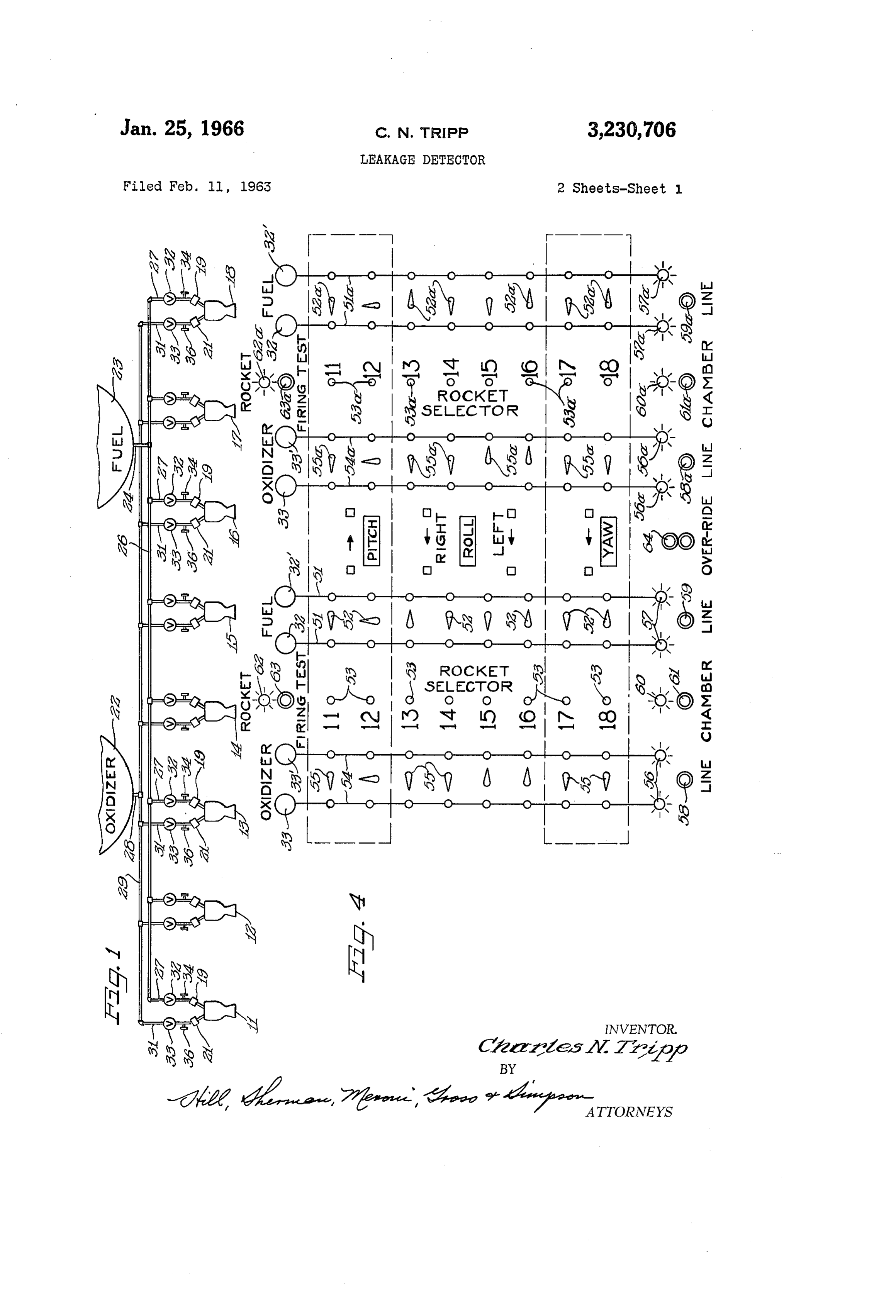
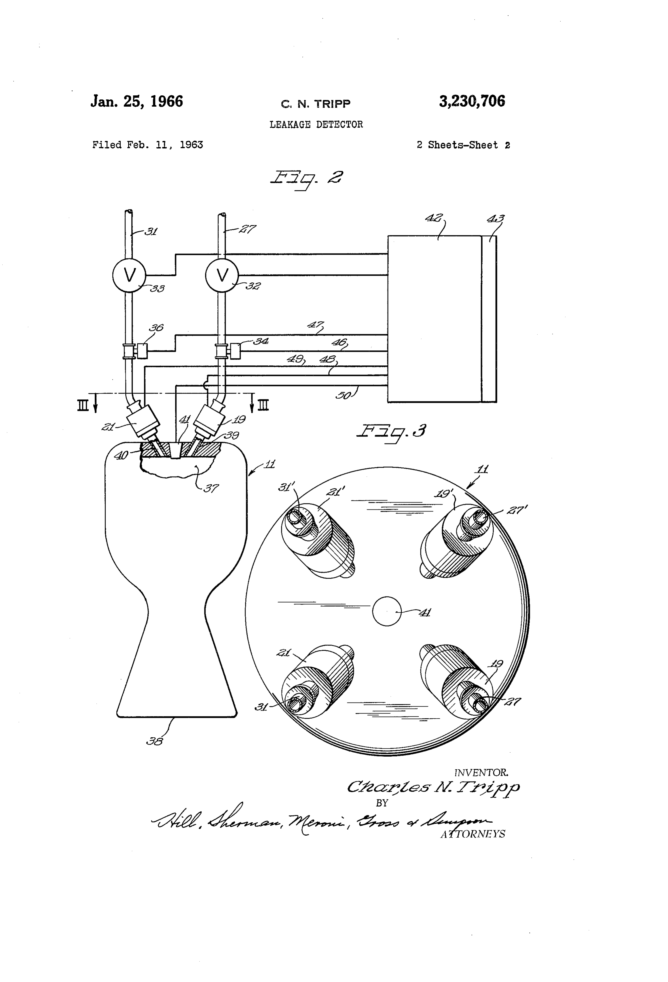
tive feed lines. Each propellant injector feed line has FIGURE 1 is a partial schematic illustration of the connected thereto an auxiliary shutoff valve and a pres control rockets of the present invention; sure decay switch for determining whether there is a leak FIGURE 2 is a schematic illustration and a partial between the injector and the auxiliary shutoff valve. transverse cross-sectional view of a rocket motor of the Also, each rocket motor contains a vacuum gauge type present invention and the control lines therefor; transducer to detect propellant leakage into its rocket FIGURE 3 is a top view of the rocket motor illus combustion chamber and a coarse detection of leakages trated in FIGURE 2 taken along lines I-II; and is furnished by the propellant tank gauge. FIGURE 4 is a schematic illustration of a readout In the case of a large leak, all the injector line valves indicator display board utilized in the present invention. are closed and then selectively open. In this manner, As shown on the drawings:
a major offender may be detected. In order to detect Referring to FIGURE 1 there is illustrated a plurality small leakage, a serial monitoring system is provided. of attitude control rockets 1, 2, 3, i4, 5, 6, 17 and The use of a multiple read-out circuitry would merely i8. Rocket motors A and 2 are utilized on the space introduce complexity and weight and would not offer 40 vehicle to control the pitch of the space vehicle; rocket compensating improvement for its detrimental complexity motors 3, 4, 5 and 6 are placed on the space vehicle and weight. Serially monitoring the rocket chamber to control the roll thereof; and rocket motors 7 and vacuum gauge transducers and then checking each of A8 are placed on the space vehicle to control the yaw the four injector lines connected to each rocket motor thereof. It is of course understood that although the to detect propellant leakage, provides the best routine. 45 present invention will be described in conjunction with Periodic checks using a systematic closing of shutoff the attitude rockets of the space vehicle, the invention valves will reveal defective transducers and in Some cases also applies to the main thrust rocket motor of the space also leaks from other than the injectors. vehicle.
Propellant leaking into the combustion chamber will, Each rocket motor has a primary fuel injector 19 and of course, evaporate and be expelled through the rocket 50 a primary oxidizer injector 25 mounted thereon. The nozzle. Initially some liquid may dribble or float out space vehicle has an oxidizer tank 22 and a fuel tank 23 of the nozzle but it is believed that under equilibrium con that supplies oxidizer and fuel to the control rocket motors ditions the gas will be constrained by choking in the as well as the thrust rocket motor (not shown). The nozzle throat. At the maximum permissible leak of control rocket motors are fed fuel by a fuel Supply pipe 10-5 pounds per second the pressure in the chamber, 24 directing fuel to a fuel manifold 25 which in turn has assuming gas dynamic relations apply, will be of the 55 connected thereto a plurality of branched oxidizer rocket order of 7 to 20 microns of Hg (depending upon the fuel feed lines 27. The oxidizer is likewise fed to the particular propellant leaking). This is near the limit rocket motors by an oxidizer supply pipe 28 connecting where gas dynamics can be used to characterize the flow the oxidizer tank 22 to an oxidizer manifold 29 having and the conditions calculated may vary Somewhat under a plurality of branched oxidizer rocket feed lines 31 ex actual circumstances. The transducer is inserted into 60 tending therefrom to feed oxidizer to the rocket motors. the combustion chamber in a relatively quiescent zone Each fuel feed line has a shutoff valve 32 therein and between the injectors. The transducer will be such that each oxidizer feed line 3i has an oxidizer shutoff valve a warning signal will occur when the pressure exceeds 33. Between the shutoff valve 32 and the fuel injector 19 a few microns of Hg. For pressures at this level and 65 is a fuel pressure decay switch 34 and between the aux higher, a hot wire type of vacuum gauge is suitable iliary shutoff valve 33 and the oxidizer injector 21 is an for pressure sensing. oxidizer pressure decay switch 36. The system of the present invention for determination Although the diagrammatic illustration of FIGURE 1 of rocket firing and propellant flow conditions has three shows only a single fuel injector 9 and single oxidizer basic sets of indicators-a contact switch at the base 70 injector 25 as well as individual feed lines therefor, it of each rocket (the rockets being mounted on unidirec is understood that there are two fuel injectors and two tional flexural supports having a force setting of a few oxidizer injectors with respective feed lines and controls
Page 4scan →
3 j??
on each rocket motor. For simplification purposes only, leg of a Wheatstone bridge circuit. Since Small electrical the auxiliary fuel injector and auxiliary oxidizer injector resistance changes must be sensed long leads between the has not been illustrated in FIGURE 1. The auxiliary transducer and the remaining bridge elements are avoided. fuel injector E9" and auxiliary oxidizer injector 21' with Resistance temperature “transmitters' have been built respective feed lines 27' and 3A," are illustrated in FIG 5 where the bridge circuit is incorporated in the transducer URE 3. body. For the vacuum threshold sensing function needed Referring to FIGURES 2 and 3, there is illustrated a in the present invention, accuracy requirements are easily single rocket motor having a combustion chamber 37 met with the standard quality resistors. and an exhaust nozzle portion 38. The rocket motor i In order to protect against thermal radiation from the O rocket walls having residual heat from firing, a radiation is used for illustrative purposes only and it is understood that the rocket motors 2, 13, E4, 25, 6, 7 and S, as shield is preferably placed around the sensing element. well as the thrust rocket motor have similar controls at The shield is oriented so that it "looks out of the hole' tached thereto and operate in a similar manner. in the exhaust nozzle.
The rocket motor a has a fuel injector conduit 39 The external circuitry of the piranni gauge will consist communicating the fuel injector 9 with the combustion of a transducer bridge element located in each rocket chamber 37. The fuel injector conduit 35 is disposed at chamber. A regulated voltage is applied across the bridge a predetermined angle to deliver the fuel to the combus calising equal current flow in corresponding arms under tion chamber in impinging relation with the oxidizcr enter conditions of pressure below the threshold. This current ing the combustion chamber. causes heating in the transducer wire which is carried away The oxidizer injector 2 has an oxidizer conduit 49 com primarily by radiation under low pressure conditions. municating the oxidizer injector 2; with the combustion The other bridge elements are made of "Evenohm' type chamber 37. The oxidizer conduit 48 is at a predeter wire to eliminate significant resistance variation with mined angle to impinge the oxidizer at a predetermined temperatures. Also, a heat conducting path is provided point in the combustion chamber 37. The size of the to aid in heat dissipation from the resistors. oxidizer conduit and the size of the fuel conduit are pre 25 Amplifying the output signal can be done in a number determined to feed the correct proportion of hypergolic of ways i.e. applying the voltage signal to the grid of a fuel and oxidizer into the combustion chamber 37 to vacuum tube biased below cutoff so that the tube will create combustion thereof. The fuel is preferably selected be conducting in the event an interrogating voltage is from the group comprising hydrazine, unsymmetrical di placed across it. A simple selective switch energizes the methyl hydrazine, and mixtures thereof, and the oxidizer 30 circuit and if a propellant leaks into any combustion is preferably selected from the group comprising red chamber, an indicator light comes on. fuming nitric acid and nitrogen tetroxide. The feed line shutoff valves, the fuel and oxidizer in The fuel and oxidizer injectors have remote control jector valves, the decay switches, and the piranni gauges valves therein (not shown) to regulate the fiow of the are all controlled by well known means. The control fuel and oxidizer to the rocket combustion chamber. The means are diagrammatically illustrated in FIGURE 2, for shutoff valves 32 and 33 and the pressure decay switches simplification purposes, as the control box. 42 having a 34 and 36 are of the well known type. The pressure control display panel 43 suitably connected thereto. decay switches 34 and 36 will sense very small losses in The shutoff valves 32 and 33 are connected to a control fuel or oxidizer trapped between respective shutoff valves 40 box 42 by suitable connecting means 44 and 45 respec 32, 33 and injectors 59, 23. The decay switches 34 and tively. Likewise, the pressure decay switches 34 and 36 36 sense a pressure differential between an initial pres are connected to the control box by suitable connecting sure condition and a subsequent pressure condition, which means 46 and 47 respectively, the solenoid valves of the may be lower than the initial pressure condition due to injectors 19 and 25 are connected to the control box by fuel leakage through the injectors 19, 21. The pressure suitable connecting means 48 and 49 respectively, and differential required to actuate the decay switches 34 the piranni gauge is connected to the control box by suit and 36 is of predetermined value which is sufficiently ably connecting means 50. The control box contains Small to cause the decay switches 34 and 36 to become all the necessary electrical equipment and switches for actuated when a very small loss of fuel or oxidizer is energizing and deemergizing the respective means by sup sensed by the decay switches 34 and 36 respectively. plying and stopping the flow of current thereto and is Inserted into the head portion of the rocket motor suitably connected to the control display panel 43 for is a vacuum gauge 4i. The vacuum gauge is placed in purposes hereinafter described. the combustion chamber in a relatively quiescent zone It is of course understood that the auxiliary injectors between the fuel and oxidizer injectors. The gauge is 9 and 21' and the auxiliary feed lines 27' and 31' with set such that a warning signal will occur when the pres their auxiliary shutoff valves and auxiliary decay switches sure in the combustion chamber exceeds a few microns 55 are similarly suitably connected to the control box 42 and of Hg i.e. 7-20 microns of Hg. In order to provide ade display panel 43.
quate strength for surviving the temperature, pressure FIGURE 4 illustrates the front of the control display and gas flow transients under combustion conditions the panel 43 which is in the cockpit of the space vehicle and gauge is of a ruggedized design of either a platinum or is utilized by the pilot thereof to detect leaks in the a tungsten carbide sensing element that has sufficient 60 space vehicle. The display selector panel has a duplicate strength to withstand combustion conditions and still read-out indicator system for ease in testing and cutting yield adequate sensitivity for measurement purposes. down on the testing time of the serial monitoring leakage Two types of hot wire vacuum gauges are used in this detection system of the present invention. Each indicator region-the piranni and the thermouple types. Both panel has numbered thereon the rocket motors to be utilize the principle of variation in heat conductivity in tested such as rocket motors 1, 2, 13, 14, 15, 6, 7 the region surrounding the hot wire due to presence of and 8 with the type of attitude control they are uti gas molecules. A calibrated input of electrical power is Iized for.
fed into the wire and the wire's change in heat balance The selector panel has two pair of fuel feed line indi noted either by change in wire temperature (thermo cators 54 and 5ia indicating the primary fuel shutoff couple gauge) or by change in electrical resistance 70 valve 32 and the auxiliary shutoff valve 32". (piranni gauge). Each pair of fuel line indicators 55 and 51a have The thermocouple gauge utilizes somewhat simpler respectively positioned therebetween a plurality of three exterior circuitry than the piranni, but has a more com position fuel switches 52 and 52a. The three-position plex transducer. The piranni gauge is preferred in the fuel switches are located so that there is one fuel switch present invention and the transducer thereof forms one beside each of the rocket motor selectors 53 and 53a.
Page 5scan →
Also, the selector panel has two pair of oxidizer feed either oxidizer or fuel to determine if an injector valve line indicators 54 and 54a indicating the primary oxidizer has failed in the closed position (and/or a shut-off valve). shutoff valve 33 and auxiliary shutoff valve 33'. Each The particular injector circuit chosen (or neutral) is indi pair of oxidizer line indicators 54 and 54a have respec cated visually by the three-position switches for each tively positioned therebetween a plurality of three-position rocket. ? oxidizer switches 55 and 55a. The three-position oxi To test for propellant leaks (still at the particular dizer switches are located so that there is one oxidizer rocket selected) the master test button 61 (labeled switch beside each of the rocket motor selectors 53 “Chamber') is pushed which will show, by the indicator and 53a. 60 lighting, that an over-threshold pressure exists in the The three-position switches 52, 52a, 55 and 55a are 0 event that a propellant leak into the combustion chamber so connected that when they point to a particular feed exists. (This is using the vacuum transducers in the line, that line has its shutoff valve open and the other chamber.) Should such be indicated, selectively switch line has its shutoff closed; when they point upwards, ing propellant lines will then isolate the particular in both lines have their shutoff valves open; and when they jector valve (or valves) leaking. point downwards, both lines have their shutoff valves 5 A redundant test system exists in the pressure decay closed. For example, rocket motor a has its three switch system. Here the injector line three-position switch position oxidizer feed line switch 55 pointing to oxidizer is placed in the middle (up) (or neutral) position which feed line 33 and rocket motor 2 has its three-position means that both injector line shutoff valves are opened oxidizer feed line switch 55 pointing upwards. There while the corresponding fuel and oxidizer injectors are fore, if rocket motor it was activated by selector 53 with 20 closed. Thus, a predetermined static pressure exists in its switch 55 pointing to the left, its oxidizer feed line the fuel and oxidizer feed lines between respective valves shutoff valve 33 would be open and its oxidizer feed line 32, 33 and injectors 9, 21. Activating the test line shutoff valve 33' would be closed. If rocket motor 12 button on the decay pressure switch circuit will close was activated by selector. 53 with its switch 55 pointing both valves to isolate the pressure between the shutoff upwards, both its oxidizer feed line primary shutoff valve 25 valves 32, 33 and the injectors 19, 25, and the pilot holds 33 and its oxidizer feed line auxiliary shutoff valve 33 the button down for a few seconds. The pressure decay would open. ? switches 34 and 36 will sense very small loss of fuel or . The selector display panel has indicator lights. 56, 57, oxidizer trapped between respective shutoff valves 32, 33 56a, and 57 a located at the bottom of each oxidizer feed and injectors 19, 21 as mentioned hereinabove. If neither line indicator 54, each fuel line indicator 51, each oxi 30 indicator light comes on after a few seconds both circuits dizer feed line indicator 54a, and each fuel line indicator will be shown to be okay. A light in either (or both) will 51a respectively; test line buttons 58, 59, 58a, and 59a indicate a leak of fuel cr oxidizer through the injector located below and between each pair of line indicator j9 and 29 respectively. The intensity of the leak is de lights 56, 57, 56a, and 57a respectively; chamber indi noted by the shortness of the time interval between the cator lights 60 and 69a, with respective chamber test instant the test switch is depressed and the instant the buttons 61 and 6a located at the bottom of the respective indicating lamp become lit. If both indicating lamps plurality of rocket selectors 53 and 53a; rocket firing become lit, but at different instances, the operator can indicator lights 62 and 62a with respective rocket firing choose the system having the largest time constant, which test buttons 53 and 63a located at the top of the respec 40 indicates the smallest leak.
tive plurality of rocket selectors 53 and 53a; and an It will be noted that the duplicate control panel is override switch 64 located at the bottom of the selector designed to provide the minimum amount of time to test panel between the line test buttons 59 and 6a. rocket motor leakage. The left and right display panel The control means 42 and display panel 43 are de are set so that their three position indicator switches are signed for a minimum of complexity and are made so that utilizing different combinations of fuel and oxidizer lines, there will be negligible power drain except when checking 45 By utilizing different combinations, the three-position is performed and so that the pilot can switch in an alter switches in one of each panel is merely turned to an nate control system for one or more axes and then can opposite feed line in order to test the four possible colm manually command firing of a given rocket. combinations offeed lines and injectors capable of use for The display panel, as illustrated in FIGURE 4, has a duplicate left and right hand control system. The panel 50 the particular rocket motor i.e. for rocket motor 11 the left-hand side of the control panel illustrates primary is connected so that depressing the rocket firing test button shutoff valve 32 open and primary oxidizer shutoff valve will temporarily interrupt (electrically) automatic firing 33 open the right-hand side of the panel illustrates second commands to all axes in the respective control system, ary oxidizer shutoff valve 33 open and primary fuel and the rocket selector. has a mechanical interlock so buttons in the left hand control system cannot be acti 55 of shutoff valve 32 open. This teaches the testing of two vated unless automatic commands to the left hand system the possible four combinations of fuel and oxidizer (by axis) cut out or automatic commands (by axis) are feed lines. The turning of the switches 52 and 52a to transferred to the right hand control system. The over their opposite directions would cause in the left-hand ride button 64 cuts out the mechanical interlock but panel oxidizer shutoff valve 33 to be open and fuel aux does not cut the function performed by depressing the 60 iliary shutoff valve 32' to be open and on the right-hand rocket firing test button. side of the panel would cause oxidizer auxiliary shutoff ... In operation, the pilot first selects and switches in valve 33 to be open and auxiliary fuel shutoff valve 32" alternatives to the axis or axes about which he is to to be open.
test. Such selection will mechanically release selector but It is of course understood, that the above leak detec tons so that he cannot erroneously check a part of the 65 tion method may be performed while the space vehicle system being used by the automatic control system. A is on its launching pad as well as when it is space borne, further interlock (electrical) exists so that the propellant Therefore, as is evidenced by the above description, I leak detector system and injector line shutoff valves can have provided an effective system for detecting leaks in not be energized while a manual firing signal is activated.
The pilot then selects a rocket for testing. A visual 70 theAlthough rocket motors of space vehicles.
various minor modifications might be apparent indication is provided as to the rocket chosen. Energizing the firing circuit should illuminate the indicator light to those skilled in the art, it is to be understood that I (paired for reliability and redundancy purposes) unless wish to embody within the scope of the patent warranted the rocket is not firing. If this latter condition is indi hereon all such embodiments as reasonably and properly cated, the pilot can switch on the alternate injector for 75 come within the scope of my contribution to the art.
Page 6scan →
claim as my invention: a fuel feed line connecting the fuel tank with the fuel 1. A leak detection system for a rocket motor having injector, a combustion chamber comprising: an oxidizer feed line connecting the oxidizer tank with 'a propellant supply tank, the oxidizer injector, a propellant feed line connecting the supply tank to the 5 each fuel and oxidizer feed line having a remote con rocket motor to supply propellant to the rocket motor trolled shutoff valve thereon, combustion chamber, each fuel and oxidizer feed line having a remote con a vacuum transducer gauge mounted within said rocket trolled pressure decay switch mounted thereon be notor combustion chamber to detect any leakage of tween the respective feed line shutoff valves and in propellant into the combustion chamber, and O jectors to detect pressure decay in the respective a decay Switch mounted on said feed line to detect any lines, leakage of propellant therein. a piranni gauge mounted within the combustion cham 2. A leak detection system for a rocket motor having ber of each rocket motor, a combustion chamber comprising: said piranni gauge being mounted between the fuel and a propellant supply tank, 5 oxidizer injectors in a relatively quiescent zone in the a propellant feed line connecting the supply tank to the combustion chamber, and rocket notor to supply propellant to the rocket motor means to selectively activate the shutoff valves, decay combustion chamber, switches, fuel and oxidizer injectors, and piranni a vacuum transducer gauge mounted within said rocket gagCS notor combustion chamber to detect any leakage of 20 whereby leakage occurring in the fuel and oxidizer feed propellant into the combustion chamber, lines and injectors is detected by serially monitoring the a shutoff valve located in said feed line to stop the flow rocket motors and their respective fuel and oxidizer feed of propellant therethrough, and lines and injectors.
a pressure responsive switch mounted on said feed line 6. A leak detection system for a plurality of rocket between said rocket motor and said shutoff valve to 25 motors on a space vehicle comprising:
detect any leakage of propellant therein. a fusel supply tank, 3. A leak detection system for a rocket motor having an oxidizer supply tank, :a combustion chamber comprising: each rocket motor having a combustion chamber, a propellant supply tank, a fuel injector mounted on each rocket motor to inject a propellant injector mounted on the rocket motor to 30 fuel into the rocket motor combustion chamber, inject propellant into the combustion chamber in re an oxidizer injector mounted on each rocket motor to Sponse to a remote signal, inject oxidizer into the rocket notor combustion a propellant feed line connecting the supply tank to the chamber in inpinging relation with said fuel, propellant injector, a fuel feed line connecting the fuel tank with the fuel a vacuum transducer gauge having its sensing means 35 injector,
Inounted within said rocket motor combustion cham an oxidizer feed line connecting the oxidizer tank with ber to detect any leakage of propellant into the com the oxidizer injector, bustion chamber, and a pirannigauge having a sensing means attached to each a decay switch mounted on said feed line to detect any 40 rocket motor, leakage of propellant therein. said piranni gauge sensing means being raounted be 4. A leak detection system for a plurality of rocket tween the fuel and oxidizer injectors in a relatively notors on a space vehicle comprising: quiescent zone within the combustion chamber, and a propellant supply tank, Said sensing element being ruggedized and made from each rocket motor having a combustion chamber, materials selected from the group comprising plati primary and auxiliary propellant injectors mounted on 45 num and tungstem carbide, whereby leakage occurring in any of the fuel and oxidizer each rocket motor to inject propellant into the rocket injectors motor combustion chamber, is detected by serially monitoring the rocket Separate propellant feed lines connecting the propellant motors and their respective fuel and oxidizer injecters. tank With the primary and auxiliary propellant in 7. A leak detection system for a plurality of rocket jectors, 50 ractors on a space vehicle comprising: teach propellant feed line having a remote controlled a fuel supply tank, shutoff valve thereon, an oxidizer Supply tank, (each propellant feed line having a remote controlled each rocket motor having a combustion chamber, pressure decay switch mounted thereon between the a primary and an auxiliary fuel injector mounted on respective line shutoff valve and injector to detect 55 each rocket motor to inject fuel into the rocket motor pressure decay in the respective feed line, combustion chamber, a piranni gauge having a sensing means mounted with a primary and an auxiliary oxidizer injector mounted in the combustion chamber of each rocket motor, on each rocket motor to inject oxidizer into the rocket Said pirannigauge being mounted between the fuel and motor combustion chamber, Oxidizer injectors in a relatively quiescent zone in 60m a primary and an auxiliary fuel feed line connecting the fuel tank with the primary and auxiliary fuel injec the combustion chamber, and tors respectively, means to selectively activate the shutoff valves, decay a primary and an auxiliary oxidizer feed line connect Switches, injectors, and piranni gauges ing the oxidizer tank with the primary and auxiliary whereby leakage occurring in any of the feed lines and 65 oxidizer injectors respectively, injectors is detected by serially monitoring the rocket a transducer vacuum gauge mounted on each rocket motors and their respective feed lines and injectors. motor, said gauge having a sensing element mounted 5. A leak detection system for a plurality of rocket between the fuel and oxidizer injectors within the motors on a space vehicle comprising: combustion chamber, a fuel Supply tank, O said sensing element being made from materials selected an oxidizer supply tank, from the group comprising platinum and tungsten each rocket motor having a combustion chamber, carbide, and a fuel and an oxidizer injector mounted on each rocket whereby leakage occurring in any of the fuel and oxidizer motor to inject fuel in impinging relationship into the injectors is detected by serially monitoring the rocket rock?t motor cofnbustion chamber, 75 motors and their respective fuel and oxidizer injectors,
Page 7scan →
8. A leak detection system for a plurality of rocket feeding fuel to the respective injectors, and each feed line motors on a space vehicle comprising: having a shutoff valve and a decay switch therein com a fuel supply tank, prising:
an oxidizer supply tank, selecting a first rocket motor to be tested and there each rocket motor having a combustion chamber, after serially testing the other rocket motors for a primary and an auxiliary fuel injector mounted on leakage, each rocket motor to inject fuel into the rocket motor testing said first rocket motor and the other rocket combustion chamber, motors thereafter by a primary and an auxiliary oxidizer injector mounted on selecting a fuel and oxidizer injector to be used each rocket motor to inject oxidizer into the rocket O for directing fuel and oxidizer into said first motor combustion chamber, rocket motor combustion chamber, firing said a primary and an auxiliary fuel feed line connecting rocket motor to determine whether said rocket the fuel tank with the primary and auxiliary fuel injec motor is operating, tors respectively, selecting the other fuel and oxidizer injector and a primary and an auxiliary oxidizer feed line connecting 15 firing said first rocket motor using the other fuel the oxidizer tank with the primary and auxiliary and oxidizer injectors to determine whether they oxidizer injectors respectively, are operating properly, each primary and auxiliary fuel feed line and each ceasing the firing of said first rocket motor, test primary and auxiliary oxidizer feed line having a re ing the pressure in the combustion chamber to mote controlled shutoff valve thereon, 20 determine whether the pressure therein is over each primary and auxiliary fuel feed line and each pri a predetermined over-threshold pressure that in mary and auxiliary oxidizer feed line having a re dicates leakage therein, mote controlled pressure decay switch mounted there opening all the feed line shutoff valves of the first on between the respective line shutoff valve and in rocket motor, jector to detect pressure decay in the respective feed 25 closing all the fuel and oxidizer injectors of the line, first rocket motor, a piranni gauge mounted on each rocket motor, said closing all the feed line shutoff valves of the first piranni gauge having a pressure sensing element rocket motor, and mounted between the fuel and oxidizer injectors with determining any pressure loss in the feed lines of in the combustion chamber, 30 the first rocket motor by the decay switch and said sensing element being made from materials selected the relative rapidity of the pressure loss between from the group comprising platinum and tungsten the feed lines carbide, and whereby leakage of propellant into the first selected rocket means to selectively activate the shutoff valves, decay motor is detected.
switches, fuel and oxidizer injectors, and piranni 35 gauges References Cited by the Examiner whereby leakage occurring in any of the fuel lines and in UNITED STATES PATENTS jectors is detected by serially monitoring the rocket motors 2,600,891 6/1952 MacNeille.
and their respective fuel and oxidizer feed lines and in 40 2,902,824 9/1959 Sponzilli ----------- 60-39.09 jectors. 3,070,676 12/1962 Moseres ---------- 340 239 X 9. A methcd of detecting propellant leaks in a plu 3,086,583 4/1963 Reichow ------------ 158-123 rality of rocket motors of a space vehicle wherein each rocket motor has primary and auxiliary fuel and oxidizer MARKNEWMAN, Primary Examiner.
injectors, a vacuum gauge in its combustion chamber, and 45 primary and auxiliary fuel and oxidizer feed lines for SAMUEL LEVINE, Examiner.
Provenance
- Collection
- Patents citing this work
- Pages
- 7
- Method
- pdftotext (the PDF's own text layer) + pdftoppm 300dpi page scans
- Patent office record
- patents.google.com →
- Source
- Google Patents citing-documents table
- Assignee
- Thompson Ramo Wooldridge Inc
- Published
- 1966-01-25
- Transcribed from
- patentimages.storage.googleapis.com →