

patent · US3230765A
Magnetically and electrically rebalanced vortex rate sensor
25 January 1966
Text
Drawings
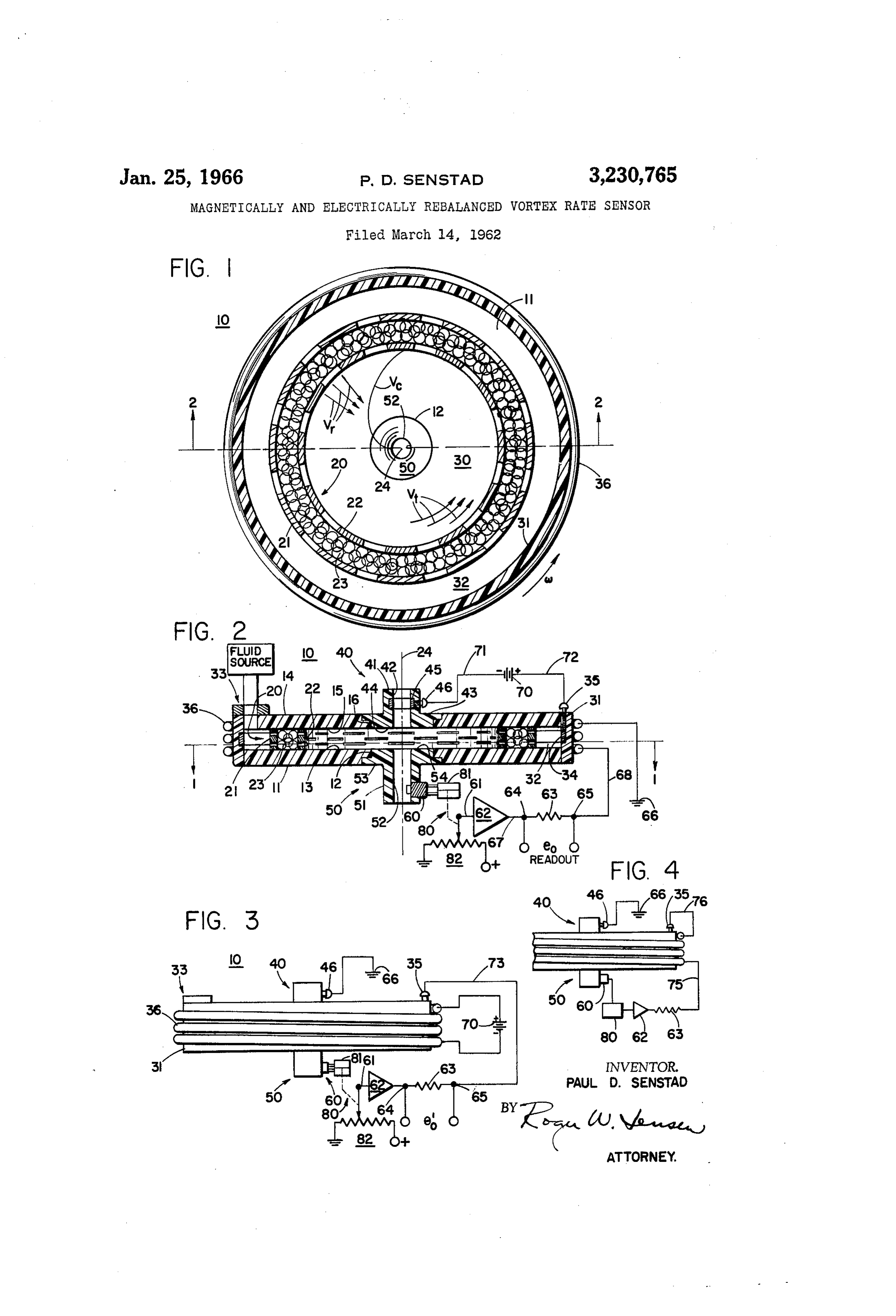
FIGURE 2 is a schematic cross-sectional view of a vortex rate sensor taken along lines 2-2 of FIGURE 1; and
FIGURE 3 is a schematic view of a vortex rate sensor illustrating an alternate embodiment of the applicant's invention; and
FIGURE 4 is a schematic view of a vortex rate sensor illustrating an alternate embodiment of the applicant's invention.
Page 1drawing sheetscan →
Page 2scan →
Magnetcally and electrically
Rebalanced vortexrate sensor
Paul D. Senstad, Golden Waley, Minn., assignor to Honeywel Inc., a corporation of Delaware
This invention relates to fluid amplifiers and more par ticularly to vortex fluid amplifiers. 10 This invention has special application to angular ve locity or rate sensing instruments commonly referred to by those skilled in the art as fluid vortex rate sensors, although the invention is by no means limited to such application. The applicant's invention will be described 5 with reference to a specific embodiment of a fluid vortex amplifier referred to as a vortex rate sensor. A vortex rate sensor is an apparatus which is capable of sensing the angular velocity (rate) about an axis of a body upon which the vortex rate sensor is applied. The 20 measurement of angular velocity (rate) is, as is well understood, useful and/or necessary in many control systems. For example, an angular velocity signal is very useful for control purposes in automatic flight and attitude control systems of aircraft and spacecraft. The 25 vortex rate sensor generally comprises a device which provides a fluid flow field which in the absence of an in put rate closely approximates the classical two dimension al pure sink flow. The fluid flow in such a pure sink flow has only radial velocity. When the fluid flow field of the vortex rate sensor is subjected to an angular ve locity relative to inertial space, a pure vortex flow having only tangential (or rotational) velocity is superimposed upon the pure sink flow. The superposition of the pure sink flow and the pure vortex flow results in a combined vortex-sink flow in which the fluid streamlined pattern is a logarithmic spiral, if the viscous effects in the flow ing fluid are neglected.
To satisfy the equation of continuity, the radial velocity of a pure sink flow will increase due to the narrowing of the streamlines as the fluid approaches the sink (also re ferred to as a core, bore, passage, or exit tube) of the vortex rate sensor. Due to the principle of the conserva tion of angular momentum, the tangential or rotational Velocity of the pure vortex flow will also increase as the flow approaches the sink. It follows that the ve locity of the fluid in the combined vortex-sink flow in creases as the fluid approaches the sink. By sensing the vorticity (rotational component) of the fluid flow within the vortex rate sensor a measurement of the input angular velocity is obtained.
Prior art vortex rate sensors have proposed a multitude of means for sensing the effect of the input angular velocity upon the fluid flow, that is, the vorticity of the fluid flow. The prior art sensing means comprise pres sure responsive means, optical means, and radioactive means. However, the prior art vortex amplifier means have limited accuracy due to the non-linearity of the out put signal. Also the prior art vortex amplifiers have a 60 limited range over which input rates may be sensed. The applicant has overcome the disadvantages of the prior art by utilizing a vortex fluid amplifier as a null reading device for sensing input rates (angular velocity). The applicant's unique rate sensing device operates as a servomechanism and obtains a readout signal which is a linear function of the applied rate (angular velocity). This results in a much more accurate readout signal than was heretofore attainable and over a much greater range than heretofore possible. This readout signal may be utilized to control any apparatus which requires such 70 information.
Patented Jan. 25, 1966
The applicant obtains this result by providing a vortex fluid amplifier utilizing an electrolyte as the fluid therein. By applying a magnetic field substantially perpendicular to the direction of current and electrolyte flow through the vortex fluid amplifier a force is applied to the electro lyte fluid tending to rebalance the vorticity or vortex flow of the fiuid. The applicant rebalances the vorticity of the vortex fluid amplifier by varying either the magnitude of the current flowing through the vortex amplifier or the magnitude of the magnetic field across the fluid vortex amplifier, or both.
it is therefore an object of this invention to provide an improved control apparatus.
This and other objects of the invention will become apparent from a study of the accompanying specification and claims in conjunction with the drawings in which: FIGURE 1 is a schematic cross-sectional view of a vortex rate sensor taken along lines - of FIGURE 2; and
FIGURE 2 is a schematic cross-sectional view of a vortex rate sensor taken along lines 2-2 of FIGURE 1; and
FIGURE 3 is a schematic view of a vortex rate sensor illustrating an alternate embodiment of the applicant's invention; and
FIGURE 4 is a schematic view of a vortex rate sensor illustrating an alternate embodiment of the applicant's invention.
Referring now to FIGURE 1, reference numeral 10 generally depicts a vortex rate sensor. A generally cylindrical electrical insulating plate element 1 is pro vided having a central aperture 12 of circular cross sec tion therein. Referring to FIGURE 2, plate element 11 has a plane surface 3 thereon. A second generally cylindrical electrical insulating plate element 4 is pro vided having a plane surface 15 thereon. Plate element 14 has a central aperture i5 of circular cross section therethrough.
Reference numeral 20 depicts a ring-shaped, or annular, or cylindrical porous coupling means. Coupling means 28 comprises a generally cylindrical outer screen element 21 and a generally cylindrical inner screen element 22. Positioned between inner screen 22 and outer screen 2. are a plurality of glass balls 23 which are very small in diameter, on the order of .015 inch, it is clear that coupling means 20 is porous in nature and allows fluid to pass therethrough with a minimum of restriction. The applicant does not wish to be limited to the particular coupling means illustrated in FIGURE 1; other suitable porous coupling means may be utilized for example sintered metals, ceramics, or the like.
Cylindrical coupling means 2i is positioned between plane surface 3 of plate element is and plane surface 5 of plate element 4 thereby maintaining plane surfaces 13 and 55 in a spaced parallel relationship. The axis of the cylindrical coupling means 20 is identified by reference numeral 24. Axis 24 is substantially perpendicular to plane surfaces 3 and 5.
Plate elements and 4 in conjunction with coupling means 20 collectively define a vortex chamber 30. The outer periphery of the chamber 30 is defined by inner screen element 22. The ends of the cylindrical chamber 30 are defined by plane surface 13 of plate element 1 and by plane surface 15 of plate element 14.
A generally cylindrically shaped electrical insulating element 3 is positioned around the cuter periphery of plate elements 1 and 14 thus enclosing the space there between. Element 31 is rigidly attached to plate elements 11 and 4 by a suitable means (not shown) such as screws or adhesives. Element 3 is spaced apart from outer screen element 21 and in conjunction there with de 3 fines a supply chamber between the plate elements 11 and positioned between two pressure ports. The pressure dif 44 which is identified by reference numeral 32. Fluid is ferential across the blade element is indicative of the fluid Supplied to the supply chamber 32 through a suitable flow pattern. The pressure output signal of pickoff means ingress 33 as illustrated in FIGURE 2. 60 is connected by suitable means to a transducer means A first generally hollow cylindrical or annular electrode 80. Transducer means 80 comprises a differential pres 34 is positioned around the outer periphery of supply Sure actuator 82 mechanically coupled to a potentiometer chamber 32. Blectrode 34 is rigidly attached to the in 82. Transducer means 80 converts the pressure signal of ner periphery of element 3 by suitable means (not sensor means 60 to an electrical signal which is indicative shown). A terrainal means 35 is positioned within ele thereof. The wiper of potentiometer 82 is connected by ment 3; one end connects to electrode 34 and the other O lead 6 to ainplifier means 62. The output of amplifier end extends to the exterior of element 3. eans 62 is connected in series relationship with readcut Positioned around the outer periphery of element 3 or resistance means 63 and coil means 36. Lead 67 coni is a coil means 36 which is illustrated as rigidly attached nects amplifier 62 to terminal 64 of readout means 63. to element 32. The function of coil 36 is to supply a Lead 68 connects terminal 65 of readout means 63 to coi Substaitially uniform magnetic flux field within vortex 35. It will be noted that the other end of coil 36 is co chamber 30 which is substantially parallel to the axis 24. nected to ground potential as at 66. The operation of coil 36 will be further discussed herein It should be noted that it is not necessary to utilize after. The applicant does not wish to be limited to the two exit passages. It is possible to utilize only a singie litilization of coil means 36 to provide a substantially exit passage in the vortex amplifier. If one exit passage uniform magnetic field within chamber 30. Other config 20 is utilized, the electrode 45 and the pickoff 60 would tlrations, e.g., a permanent magnet, are within the scope both be located therein.
of the applicant's invention. it should be noted that it is within the scope of the A first exit member 46 is provided. Exit member 40 invention to interchange the relative directions of the comprises a tube or fluid conduit 41 having a generally current flow and magnetic flux flow. That is to say, the cylindrical bore or passage 42 therethrough. The ap only requirement in obtaining a rebalance force upon the plicant does not wish to be limited to a cylindrical pas filid is that a coingonent of a magnetic flux field and a Sage, other configurations are within the scope of this component of a current are perpendicular thus produc invention. Conduit or tube 41 has an external fiange por ing a force upon the fluid mutually perpendicular to the tion 43 on one end thereof. The flange portion 43 is magnetic fux flow and the current flow. positioned with aperture 16 of plate element 14 so that Operation the bore 42 of exit member 20 is positioned substantially coaxial with axis 24. However, other configurations of In operation, a pressure differential exists between pas the vertex rate sensor in which the exit passage is delib sages 42 and 52 of exit members 40 and 50 respectively, erately offset from the axis 24 (not coaxial) to take advan Consequently an electrolytic fluid flows through coupling tage of the flow characteristics may be utilized. An end means 28, through chamber 30, and exhausts through surface 44 of exit member 40 is positioned so as to lie in passages 42 and 52. In the absence of any input (angular the same piane as the plane surface 15 of plate element Velocity about axis 24) the fluid flow has only radial 14. Exit member 4 is rigidly attached to plate E4 by velocity as illustrated by the vectors V, in FIGURE 1. suitable means (not shown) such as adhesives or screws. 40 This radial flow is described by those skilled in the art A Second generally hollow cylindrical or annular ele as a pure sink flow. The radial velocity of the fluid in ment 45 is positioned around the periphery of passage 42. creases as the fluid approaches passages 42 and 52. It will be noted that electrode 45 is recessed within tube 42 When the vortex rate sensor 10 is subjected to an in and attached thereto by suitable means (not shown) so put rate, that is an angular velocity w about the axis 24, that the inner periphery of electrode 45 is flush with the the fluid which is flowing thorugh coupling means 20 is passage 42. A terminal means 46 is positioned within 45 given a tangential or rotational velocity as illustrated element 4; one end of terminal 46 connects to electrode by the vectors V in FIGURE 1. A flow field of tangen 45 and the other extends to the exterior of tube element 4E. tial or rotational veiocity only is referred to by those Electrodes 34 and 45 are connected across a current skilled in the art as a pure vortex flow. The tangential source 78. Terminal 45 is connected to one side of cur or rotational velocity of the fluid increases (VXR= rent source 70 by lead 75. Terminal 35 is connected to Constant) as the fluid approaches the passages 42 and 52, the other side of current source 70 by lead 72. in accordance with the application of the principle of con A second exit member 50 is also provided. Exit mem servation of angular momentum.
ber 58 comprises a tube or fluid conduit 5A having a The Superposition of a pure vortex flow upon a pure generally cylindrical bore or passage 52 therethrough. sink flow results in a combined vortex-sink flow. The The applicant does not wish to be limited to a cylindirical streamline pattern of the fiuid in the combined vortex passage, other configurations are within the scope of the sink flow is logarithinic spiral as identified by reference applicant's invention. Conduit or tube. 51 has a flange Symbol V in FIGURE 1. As fiuid flowing in the log portion 53 on one end thereof. The flange portion 53 is arithmic spiral flow pattern reaches the sink it flows out positioned within the aperture 2 of the piate element a of the chamber 30 into passages 42 and 52. This results so that the bore 52 of exit member 50 is positioned sub 60 in a fuid flow pattern in a form of a helix in passages stantially coaxial with the axis 24. However other config 42 and 52. That is, there is a component of fluid flow urations of the vortex rate sensor in which the exit pas having a longitudinal velocity parallel to the axis 24 sage is deliberately offset from axis 24 (not coaxial) to and a component of fluid flow having a rotational velocity take advantage the flow characteristics may be utilized. perpendicular to axis 24. It should be noted that the An end surface 54 of exit member 5 is positioned so as component of fluid flow within passages 42 and 52 pers to lie in the same plane as the plane surface 3 of plate pendicular to the axis 24 is indicative of the input rate member 1. Exit member 58 is rigidly attached to plate cw. Consequently, it is possible to determine the input member by suitable means (not shown) such as ad rate a by Sensing the tangential component of the fluid hesives or screws. flow.
A pickoff means 69 is positioned within exit tube 50. 70 The applicant has provided an improved rate sensing A suitable pickoff means is disclosed in the copending device by utilizing a basic vortex rate sensor and modi. application Serial No. 156,613, filed December 4, 1961, fying it to produce a null reading device. That is, the in the name of Richard J. Reilly, and assigned to the same voteX rate sensor is operated by the applicant as a servo assignee as present application. The copending applica mechanism system. The vorticity of the rate sensor is tion discloses: a fluid flow sensor utilizing a blade element rebalanced by applying a force to the fluid to substan 4 tially null out the vorticity. This null reading vortex in operation, the magnitude of both the current and the magnetic field are varied in response to the signal gener rate sensor will operate with a very minimum of actual vortex flow and consequently will obtain a readout which ated by pickoff means 60 so as to rebalance the vortex is a linear function of the applied angular velocity about flow of the fluid and the voltage across readout means 63 axis 24. In addition, the useful range of the vortex is indicative of the input angular rate. rate sensor is increased by utilizing it as a servomecha The applicant's invention as disclosed in FIGURES 1-4 S. has utilized direct current energization. However, it is In order to apply a rebalance force to the fluid of within the scope of this invention to utilize alternating the vortex rate sensor the applicant utilizes an electro current energization.
lyte as the fluid. A voltage is set up across the vortex O Thus the applicant has provided an improved vortex chamber 30 between electrodes 34 and 45 and a current rate sensing instrument. The vortex rate sensor is utilized is conducted by the fluid within the chamber 30, sub as a null reading device and thus produces an output stantially perpendicular to the axis 24 in a radial di signal which is a linear function of the input rate. Fur rection. In one embodiment of the applicant's invention ther, the useful range of the rate sensing instrument is the magnitude of the current flowing in the chamber 30 increased by utilizing it as a null reading device. The is maintained constant. When the vortex rate sensor vortex rate sensor is rebalanced by applying a force to 10 is subjected to its angular rate about axis 24 pickup the fluid as a result of the interaction of a current and means 60 immediately senses this rate and conducts a a magnetic field.
pressure signal indicative thereof to transducer means 80. While I have shown and described a specific embodi More specifically the pressure differential is conducted 20 ment of the invention further modification and improve ment will occur to those skilled in the art. I desire to be from sensor 60 to the differential pressure actuator 81. understood
Actuator 81 is displaced in response to the differential therefore that this invention is not limited to pressure signal and repositions the wiper of potention the particular form shown and I intend in the appended eter 82. The electrical signal developed in potentiom claims to cover all modifications which do not depart eter 82 is indicative of the pressure signal of sensor 60. 25 from the spirit and the scope of this invention. The electrical signal is conducted through the wiper of What I claim is:
the potentiometer and lead 61 to amplifier means 62. 1. In a vortex fiuid amplifier including a cylindrical The output of amplifier means 62 is connected to coil chamber; a source of conductive fluid, means for gener means 36 so that a current is conducted therein. The ating a radial fluid flow within said chamber; means for existence of a current within coil 36 results in a magnetic 30 sensing vortical fiuid flow; means effective to maintain a field, within chamber 30 substantially perpendicular to Substantially constant radial electrical current through the direction of the current flowing in chamber 30 (that said conductive fluid in said chamber; means for produc is, parallel to axis 24). The magnitude of the magnetic ing an axial magnetic field within said chamber includ field is indicative of the input rate. Consequently a force ing conductor means, amplifier means, and transducer is exerted upon the fluid flowing within chamber 30 35 means; means connecting the Sensing means to said trans which acts at right angles to both the direction of the ducer means; means connecting said transducer means to current and the direction of the magnetic field. This Said amplifier means; and means connecting said ampli force tends to rebalance the fluid flow within chamber fier means to said conductor means, so that said conductor 30 and substantially to eliminate the vorticity or vortex means is energized as a function of signals produced by flow pattern therein. The voltage e across readout means 40 said sensing means.
63, is then indicative of the angular input rate. 2. In a vortex fluid amplifier including a cylindrical An alternate embodiment of the applicant's invention chamber; a source of conductive fluid, means for gener is illustrated in FIGURE 3. The components illustrated ating a radial fluid flow within said chamber; means for in FIGURE 3, which are identical to the components Sensing vortical fluid flow; means effective to produce a radial electrical current through said conductive fluid in illustrated in FIGURE 2, are identified by the same reference numeral as in FIGURE 2, Voltage source said chamber including transducer means and amplifier 70 is connected across coil means 36 thus supplying a means; means for producing a substantially constant axial substantially constant magnetic field within chamber 30 magnetic field within said chamber including conductor parallel to the axis 24. Terminal 46 connects electrode means; and means connecting the sensing means to said 45 to ground potential at 66. Electrode 34 is connected transducer means, means connecting said transducer by terminal 35 and lead 73 to the output of amplifier 62. means to said amplifier means, means connecting said Any input (angular rate) about axis 24 is sensed by pick amplifier means to said means for producing a radial cur off means 60 which produces a signal indicative thereof. rent through said chamber, said current producing means The signal is conducted through lead 61 to amplifier 62. being energized as a function of signals produced by said The output of amplifier means 62 is conducted through Sensing means.
lead 73 to terminal 35 and electrode 34. Consequently, 3. In a vortex fluid amplifier including a cylindrical a potential is set up between electrodes 45 and 34 which chamber having a conductive fluid therein; means for is indicative of the input angular rate. Thus by varying causing a normally radial flow of said conductive fluid the potential and thus the magnitude of the current with within said chamber, rotation of said chamber causing a in chamber 30 and by maintaining the magnetic field 60 Vortical fluid flow; means for sensing said vortical fluid constant within chamber 30 the vortex fluid flow is re flow; means for generating an electric field and means for balanced in a manner analogous to the previously ex generating a magnetic field perpendicular thereto to pro plained. duce a force field on said fluid in said chamber as a func An alternate embodiment of the applicant's invention tion of signals produced by the sensing means; and means is illustrated in FIGURE 4. The magnitude of both the 65 connecting the Sensing means to the generating means so current and the magnetic field is varied in response to the that said means for generating force field produces a force signal generated by pickoff means 69. In this embodi in Said conductive fluid in said chamber of such a sense ment, the coil 36 and the electrode 34 are connected in as to oppose the vortical flow in said chamber. series relationship with pickoff means 60. With reference 4. In a vortex fluid amplifier including a cylindrical to FIGURE 4 coil 36 is connected in series relationship 70 chamber; a source of conductive fluid; said chamber with pickoff means 60, transducer means 80, amplifier adapted to be connected to said fluid source; means for means 62, readout means 63 by suitable means including generating a radial fluid flow within said chamber; means lead 75. Coil 36 is also connected in series relationship for Sensing vortical fluid flow; means effective to maintain with electrode 34 by means of lead 76 and terminal 35. a Substantially constant axial magnetic field through said Electrode 45 is connected to ground potential 66. Thus, chamber; means effective to produce a radial electric cur 5 rent within said, chamber; readout means; first connecting chamber; a source of conductive fluid; said chamber means connecting said sensing means to said readout adapted to be connected to said fluid source, means for means; and second connecting means connecting said generating a radial fluid-flow within said chamber; means readout means to said means for producing a radial cur for Sensing vortical fluid flow; means effective to produce Irent. a current through said chamber and conductive fluid in 5. In a vortex fluid amplifier including a cylindrical Said chamber; means for producing a magnetic field within chamber; a Source of conductive fluid; said chamber said chamber substantially perpendicular to said current; adapted to be connected to said fluid source, means for readout means; and means connecting said sensing, means generating a radial fluid flow within said chamber; means to said read out , means, means connecting said readout for Sensing vortical fluid flow; means effective to maintain O neans to Said magnetic field producing means, means a Substantially constant current through said chamber and Coinnecting said magnetic field producing means to the conductive fluid in said chamber; means for producing a current producing means so that a force field is generated magnetic field within said chamber substantially perpen as a function of signals produced by said sensing means dicular to said current; readout means; and means con So as to apply a force to the conductive fluid in said cham necting said sensing means to said readout means, means 5 ber So as to oppose the vortical flow sensed by said sens connecting Said readout means to said magnetic field pro iing means.
ducing means, Said magnetic field producing means being energized as a function of signals produced by said sens References. Cited by the Examiner ing means. UNITED STATES PATENTS 6. In a vortex fluid amplifier including a cylindrical 20 chamber; a source of conductive fluid; said chamber 1,841,606 1/1932 Kollsman.
adapted to be connected to said fuid source, means for 2,203,824 6/1940 Kollsman ----------- 33-204 generating a radial fluid flow within said chamber; means 2,215,447 9/1940 Kolisman --- 33-204 for Sensing vortical fluid flow; means effective to produce 3,029,644 4/1962 Loveless et al. an electrical current through said chamber and conduc 25 3,034,002 5/1962 Carlson.
tive fluid in Said chamber; means for maintaining a sub stantially constant magnetic fied within said chamber FOREIGN PATENTS
Substantially perpendicular to said current; readout means; 116,375 6/1918 Great Britain.
and means connecting Said Sensing means to said readout means, means connecting said readout means to said cur 30 OTHER REFERENCES rent producing means, said current producing means be Pingelly: Journal of Applied Physics, Jan. 1957, vol. ing energized as a function of signals produced by said 28, No. 1, pp. 86 to 92.
Sensing means So as to apply a force to the conductive fiuid in said chamber so as to oppose the vortical flow by RICHARD C. QUESSER, Primary Examiner. Said sensing means. 35 SAMUEL FEINBERG, BENJAMEN A. BORCHELT, 7. In a vortex fluid amplifier including a cylindrical ROBERT EVANS, Examiners.
Provenance
- Collection
- Patents citing this work
- Pages
- 5
- Method
- pdftotext (the PDF's own text layer) + pdftoppm 300dpi page scans
- Patent office record
- patents.google.com →
- Source
- Google Patents citing-documents table
- Assignee
- Honeywell Inc
- Published
- 1966-01-25
- Transcribed from
- patentimages.storage.googleapis.com →