

patent · US3236284A
Monitoring system for a combustion apparatus and the like
22 February 1966
Text
Page 1bibliographic recordscan →
Feb. 22, 1966 J. W. KEMPER 3,236,284
MONITORING SYSTEM FOR A COMBUSTION APPARATUS AND THE LIKE
Filed Jan. 2, 1963 3. Sheets-Sheet l
Š Sf ".
SNSS
SSS
SSS
SSSS
N N :
t S. () s Ea Na/ QS S
INVENTOR
Vosézé W. Aéroper
Drawings
Page 2drawing sheetscan →
Page 3drawing sheetscan →
Page 4scan →
United States Patent Office 3,236,284 Patented Feb. 22, 1966
3,236,284 pliance having a first gas line communicating with the
MONITORNG SYSTEM EFOR A COMBUSTION main gas supply line and communicating with a moni APPARATUS AND THE LIKE toring pilot upstream of the main supply line shut-off Joseph W. Kemper, 419 N. Maple Ave., Danville, Ky. valve, and another second gas line communicating with Filed Jan. 2, 1963, Ser. No. 249,035 the main gas supply line to the appliance and the moni 1. Claims. (Cl. 158-122) toring pilot, which second line is located downstream of the main shut-off valve disposed in the main gas line
The present invention relates to a combustion appara stream for supplying any gas leaking past the main shut tus, and, more particularly, to a signal indicating System off valve to the monitoring pilot to signal a gas leak in or safety means for such apparatus. 0. the main shut-off valve or other malfunctions in the system. The invention will be described and illustrated in con It is another object of the present invention to provide nection with a combustion apparatus such as a furnace, a monitoring system for a gas-fired apparatus having a oven, or the like, which utilizes a combustible vapor or Suction gas line and air supply means communicating with gas to produce heat energy, though it is apparent that the a monitoring pilot which maintains a negative or suction invention is not to be limited thereto, but may be used 5 pressure on the suction line in order to send any gas leak with various types of appliances and systems. Other ing past the main shut-off valve of the appliance when it applications of the invention would be, for example, is in stand-by or shut-down operation, to the monitoring checking for sewer gas accumulations escaping into build pilot So that the system may signal a hazardous condition. ings through drainage systems, gas accumulations occur It is another object of the present invention to pro ring in contained pockets in structures, but to mention a 20 vide a gas appliance having a main gas supply line with a few. main shut-off valve therein that is normally open when In the use of combustion apparatus in which a com the appliance is in operation and normally closed when bustible gas such as natural or liquid propane gas is burned the appliance is shut down and in stand-by condition, and in heating boilers, domestic hot water heaters, ovens, in gas pilot means in communication with the upstream side cinerators, process boilers and the like, the apparatus or 25 of the shut-off valve, which gas pilot means normally has appliance is generally of an automatic recycling type. flowing therethrough a predetermined volume of gas, and That is, the equipment is generally in operation for short another suction gas line in communication with the con periods of time after which it is shut down for a short stant or monitoring pilot that is located downstream of period of time. In other words, it has intermittent op the main shut-off valve, and which suction line is pro eration and the appliance is generally started and Stopped 30 vided with Solenoid valve means therein, normally closed at the signal of an automatic controller which may be ac when the main gas line shut-off valve is open, and which tuated by temperature, pressure, or the like. This type Solenoid valve means is normally open when said main of appliance is normally unattended by any operating shut-off valve is closed so that any gas leaking past the personnel, since it is automatic in operation and, there main shut-off valve will be supplied to the monitor pilot fore, one hazard encountered by such an appliance is the 35 to increase the gas flow thereto above a predetermined possibility that during a stand-by period or a period in value or volume, which will cause an alarm or detector which it is not in operation, a gas leak may occur there means to signal that there is a gas leak in the main gas by resulting in a large accumulation of combustible gas line, or that other components of the alarm system are malfunctioning.
which can result in an explosion if the detection of it is not quickly noticed. 40 It is another object of the present invention to provide It is an object of the present invention to provide an a monitoring system for a gas-fired appliance which will apparatus provided with protective or safety means for indicate a malfunction in the air supply means which op detecting any malfunction of the apparatus to prevent an terates to Suck any gas leaking past the main shut-off valve accumulation of combustible gases in order to prevent of the appliance to the monitor pilot which will indicate any damage or explosion due to such accumulation of 45 if the main gas line shut-off valve remains open when the aSeS. gas appliance burner means is not in operation, and will S. It is another object of the present invention to provide indicate if the solenoid valve means located in the suc a combustion appliance or apparatus that is fired by a tion line of the monitoring system fails to open when the combustible gas with safety means for detecting the leak appliance is shut down.
age of gas into the area of the appliance when the ap It is also an object of the present invention to provide pliance is in a shut-down condition and not in operation. a monitoring System for a gas-fired appliance in which the It is another object of the present invention to provide monitoring pilot system is provided with a monitor pilot a monitoring system for a gas-fired appliance with a con that can be the gas pilot for the appliance. Stant burning pilot or monitoring means in which a por It is another object of the present invention to provide tion of the main gas stream of a predetermined value or a monitoring system for a gas-fired appliance provided quantity is passed through the constant burning pilot with a constant burning pilot that is always supplied with means, and any increase above the predetermined value a predetermined volume of gas when the appliance is will cause an alarm or signaling means to indicate there is turned on, regardless of whether the gas burner means of leakage of the combustible gas through the main gas the appliance is being fired or is in a stand-by condition. stream line when the appliance is not in operation. 60 It is another object of the present invention to provide It is another object of the present invention to provide a monitoring System for a gas-fired apparatus having a a monitoring system for a combustion apparatus in which monitoring system for detecting gas leaks, which moni a constant burning pilot or monitoring means that com toring System includes a constant burning pilot connected municates with the main gas stream or line is also pro upstream of the main shut-off valve of the main gas line, vided with another small gas line in communication with 65 and a suction line with solenoid valve means therein in the main gas stream line and the monitoring pilot with communication with the constant burning pilot and air valve means therein for sampling and increasing the flow supply means for creating a negative pressure on the suc of gas to the monitoring pilot when a gas leak occurs in tion line means having venturi means therein for remov the main gas supply line to the appliance.
It is another object of the present invention to provide O ing any gas which flows into the suction line downstream a safety system for the main gas supply line to an ap of the main shut-off valve of the main gas line to the appliance.
Page 5scan →
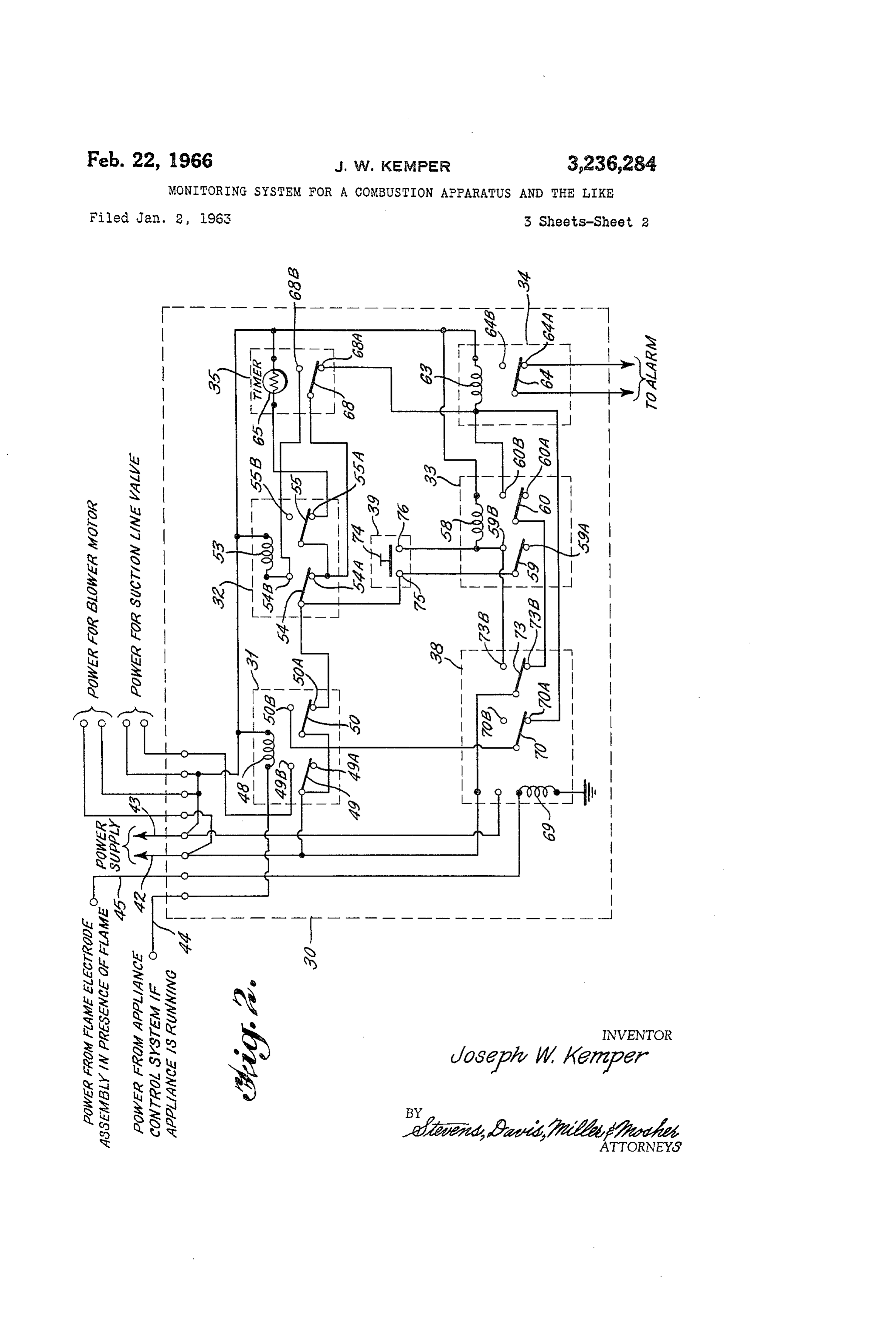
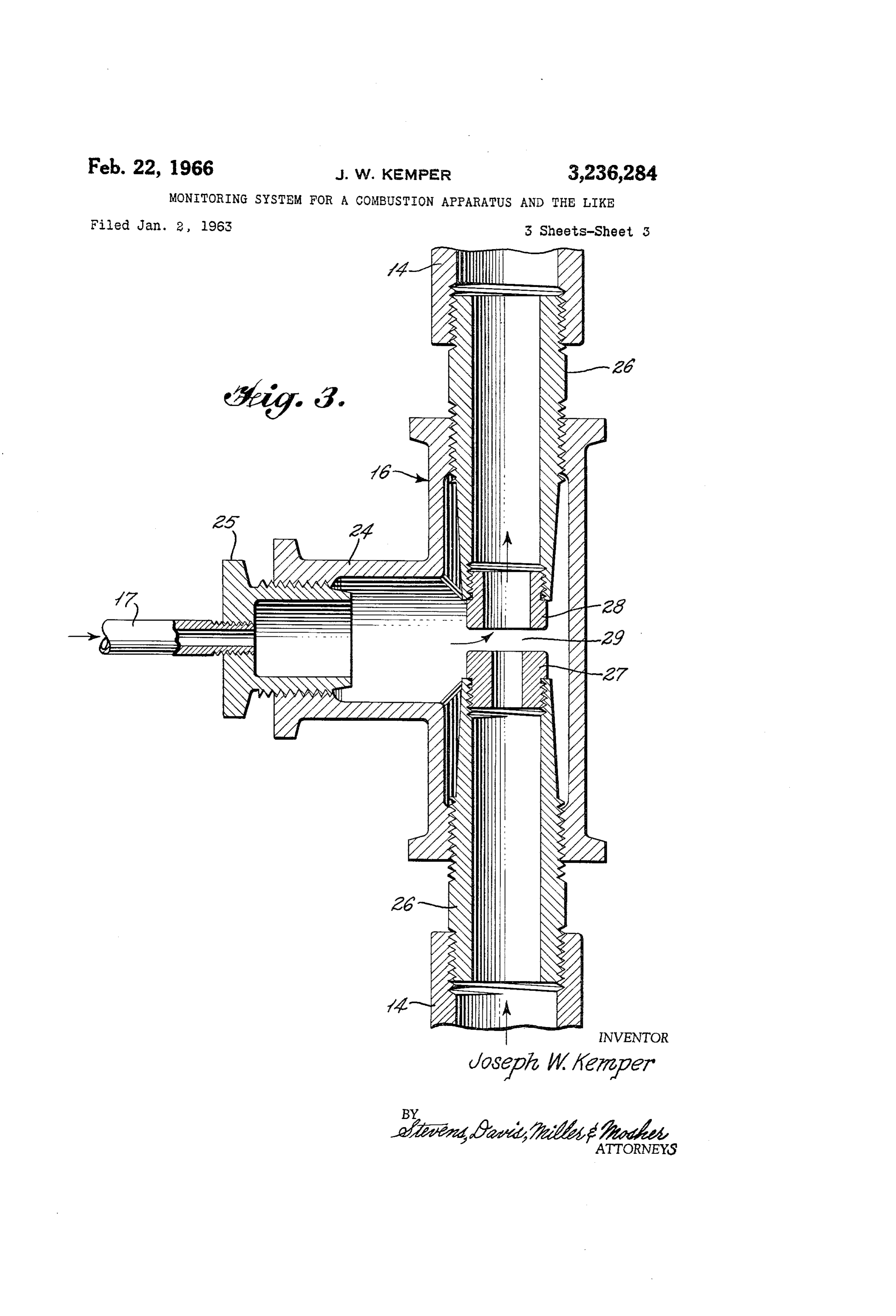
Various other objects and advantages of the present their outer ends connected to line 14 externally threaded invention will be readily apparent from the following while their inner ends disposed within housing 24 are detailed description when considered in connection with internally threaded. The inner ends of bushings 26 are the accompanying drawings forming a part thereof and of a diameter substantially less than the inside diameter in which: of housing 24 and gradually taper inwardly. The spacing FIGURE 1 is a view of the apparatus embodying the between the adjacent ends of bushings 26 can be varied present invention; by threading them inwardly or outwarly of the housing FIGURE 2 is a schematic diagram of the electrical the distance desired.
circuit of the monitor electric panel embodied in the pres An air jet outlet opening or passage is provided by an ent invention; and O air jet orifice or nozzle member 27 having external threads FIGURE 3 is a detailed view of the vacuum or suction on one end secured to the internal end threads of the puller means embodied in the present invention. bushing 26 connected to the air blower side of line 4. Referring to FIGURE 1, the reference numeral 2 gen The cross-section of the air jet passage is constant and erally designates a gas-fired furnace or appliance pro higher pressure air, for example one inch water column, vided with a main gas supply line 3 extending therein for is discharged therethrough into the mixing throat of the supplying combustible gas to fire the furnace. A manual device.
gas shut-off valve 4 and a pressure regulator valve 5 and The mixing throat is provided by a throatbushing mem a main gas supply shut-off valve 6 are disposed in the ber 28 having an axial bore or passage extending there gas line 3. The shut-off valve 6 is a solenoid valve and through and with external threads which are secured to is automatically controlled by the electrical system 23 20 the bushing 26 connected to the pilot side of line 4. As for controlling the appliance operation. The solenoid FIG. 3 clearly shows the cross-sectional area of throat valve 6 is normally open when the gas furnace is fired member 28 is constant and is substantially larger than the so as to supply gas to the burner 7 in response to tempera cross-sectional area of air jet nozzle 27. These two mem ture, pressure or other similar condition. When the fur bers are also designed so that their adjacent ends are nace and the burner 7 are in a stand-by condition, that spaced apart to provide a chamber 29 in communication is, when no heat energy is required by the furnace, the with the interior of the housing. If the cross-sectional electrically cperated solenoid gas valve 6, which stops area of the air jet to the throat cross-sectional area is kept and starts the flow of gas to the gas burner 7, is shut off in a ratio, preferably of 1 to 1.2, and if the total open area or closed. Since this is an automatic system, the appa between the end of the air jet and end of the throat is ratus is generally unattended by operating personnel. One 30 greater than the suction line opening, a vacuum is de of the hazards created by the use of the combustible gas veloped and maintained at a ratio of substantially 1 to 1 for firing the furnace is the possibility that during a relative to the air discharge pressure. stand-by period or a period when the appliance does not Thus, device 16 is a negative producing device, pro call for heat energy, a gas leak may occur in the main vided with a fixed air jet discharging air into an adjacent gas line shut-off valve 6. It is, of course, apparent that slightly larger air throat, producing a negative pressure if the valve 6 is not fully closed or there is leakage thereby or Suction in chamber 24 and the interior of the housing, due to its improperly seating on its valve seat or for any so that as the fan 12 is put into operation, it will cause other reason, the gas will be supplied to the furnace 2 and any gas in the suction line 17 to be pulled therefrom an accumulation of the gas will be hazardous. through connection i6 and into the air line 14 to be sup The system is provided with a constant burning pilot 40 plied to the pilot 8, along with the constant supply of 8 in communication with the main gas line 3 upstream of flow of gas through the line 9 to thereby increase the or on the inlet side of the main shut-off valve 6 through volume of gas being consumed by the burning pilot. the small pipe or line 9. The pipe 9 is provided with a This will cause the pilot flame to expand in size and make manual shut-off valve 10 that is normally in an open contact with the flame electrode 2E which is disposed in position whenever the system is turned on, whether the the electrical System to indicate that gas is present in the main gas valve 6 is in a closed or an opened position. main gas line 3 downstream of the shut-off valve 6 and is This line is also provided with a gas pressure regulator 11 leaking through the valve when it should not be. This to control the flow of gas to the monitoring pilot 8. The malfunction of the main shut-off valve 6 indicating it is pilot 8 can be the furnace pilot and is supplied with a either open or it is not properly seated and that gas is predetermined value or volume of gas whenever the sys 50 passing through the line 3 so as to accumulate in the tem is in operation, for example, at the rate of 1 cubic area of the furnace will be transmitted through the moni foot of gas per hour. for electrical panel 30 to sound an audible alarm 22 or The air to support combustion is provided by a blower close off a back-up safety valve or other safety means in or fan 12, driven by a motor 13, through a pipeline or the system. The reference numeral 23 designates a sepa an air supply line 14 communicating with the fan at one rate control system for controlling the appliance opera end and the pilot 8 at the other. The air supply line 14 tion.
is provided with a T-fitting member 15 that is connected Referring to FIGURE 2, the monitor electrical panel to the constant gas flow line 9 with an orifice therein in 30 is composed of a plurality of switching relays 3A, 32, the portion of 15 connected to the gas line 9. The air 33 and 34, a motor driven timer 35, an electronic flame supply line 14 is also provided with another enlarged T 60 detector relay 38 such as the Minneapolis-Honeywell Type connection or member 6 connected to a suction or nega R7023A, and a starter switch 39. A suitable source of tive pressure or eduction line 17. The suction line 17 is electrical power, not shown, is connected to supply ter connected to the main gas supply line 3 downstream of or minals 42 and 43 of the panel 30. The panel 30 also on the outlet side of the solenoid valve 6 and is provided has a terminal 44 connected to the gas appliance control with a solenoid valve 8 therein. The member i6 is a system 23, and a terminal 45 connected to the flame elec vacuum or suction puller means, as best shown in FIG. 3, trode 2. Electrical current flows between the terminals and consists of an outer tubular casing or housing 24 with 44 and 43 through relay coil 48 when the gas appliance three internally threaded openings for receiving fittings or 2 is being operated. Electrical current flows between ter adapter bushings therein. The opening at the base of the minal 45 and ground through a flame detector relay coil T is connected to suction line 17 by an externally-threaded 69 upon energizing flame detector relay 38. bushing 25 secured therein and provided with a smaller The relay 31 is composed of relay coil 48, an armature threaded opening in its head or flange portion to which contact 49 that is movable for making a connection with the suction line or pipe 7 is threadably secured. one or the other of two terminals 49A and 49B, and an The other two openings have identical elongated sleeve armature contact 50 that is movable for making a con bushings 26 threadably secured therein. Bushings 26 have nection with one or the other of two terminals 50A and
Page 6scan →
50B. The arrnature contacts 49 and 50 are shown in to any of the monitor control panel input terminals 44, their normal positions when the gas appliance 2 is turned 45, 42, and 43. Under these conditions, the armature “off” and relay coil 48 is de-energized. The armature contacts and switches of the control panel all are in the contacts 49 and 50 are spring biased in their normal posi positions shown in FIGURE 2.
tions until the relay coil 48 is energized. They return to Assuming that the appliance is turned “off” and no their normal positions when the coil 48 is de-energized. power is supplied to input terminal 44, assume further that The relay 31 has overlap contacts, i.e., the normally open terminals 42 and 43 are energized by a 120 volt power contacts make before the normally closed contacts break. source, for example, which power source has just been The relay 32 is composed of a relay coil 53, an arma turned “on.” Current flows through the four armature ture contact 54 for making a connection with one or the O contacts 49, 50, 54 and 55 to the timer motor 65. The other of two terminals 54A and 54B, and an arnature armature contact 68 does not move immediately because contact 55 for making a connection with one or the other of the delay introduced by the motor 65, and current of two terminals 55A and 55B. The armatures contacts also flows through the armature contact 68 and the coil 54 and 55 are shown in their normal positions, relay coil 63 of relay 34. Armature contact 64, therefore, moves 53 being de-energized. The armature contacts 54 and 5 from its normal position to its other position, thus open 55 are spring biased in normal positions until the relay ing the contacts 64 and 64A to keep the alarm 22 from coil 53 is energized, and return to normal positions when being actuated.
the coil 53 is de-energized. At the end of the delay produced by timer 35, the The relay 33 is composed of a relay coil 58, an arma armature Switch 68 moves from its normal posoition in ture contact 59 for making a connection with one or the 20 contact with terminal 68A to its other position in contact other of two terminals 59A and 59B, and an armature with terminal 68B, whereby the alarm relay coil 63 is contact 60 for making a connection with one or the other de-energized and the relay coil 53 becomes energized. of two terminals 60A and 60B. The armature contacts The armature contact 64 of relay 34 returns to its nor 59 and 60 are shown in normal positions, relay coil 58 mal position, and the armature contacts 54 and 55 of being de-energized. The armature contacts 59 and 60 25 relay 32 change from their normal positions to their are spring biased in normal positions until the relay coil other positions. A holding circuit is created to the relay 58 is energized, and return to normal positions when coil 53, and the power supply to the timer motor 65 is the coil 58 is de-energized. broken. At this moment the armature contact 68 of The relay 34 is composed of a relay coil 63, and an the timer 35 returns to its normal position, but no power armature contact 64 for making a connection with one 30 is Supplied to the alarm relay coil 63 because the arma or the other of two terminals 64A and 64B. The arma ture contact 54 has been disconnected from terminal 54A. ture contact 64 is shown in its normal position, relay coil By pressing the momentary start button 74, power is 63 being de-energized. The armature contact 64 is spring Supplied to the relay coil 58 of relay 33. The armature biased in its normal position until the relay coil 63 is Switch 59 completes a holding circuit for relay 33, and energized, and returns to its normal position when the the alarm relay coil 63 receives power from the terminals coil 63 is de-energized. 42 and 43 through the armature contacts 60 and 73. The timer 35 is composed of a motor 65, and an arma This opens the armature contacts 64 and 64A and the ture switch 68 for making a connection with one or the alarm 22 is inoperative.
other of two terminals 68A and 68B. The timer is driven The monitor electrical panel 30 is now in the proper by the motor 65, and is adjustable by means, not shown, 40 Sequence for automatic supervision of gas leaks. Gas for moving switch 68 from terminal 68A to the terminal to the constant burning pilot 8 is turned on, and the 68B at the end of a time interval from ten to one hun pilot is lit. With the monitor panel 30 in a stand-by dred eighty seconds, for example. At the moment motor condition and the main gas appliance 2 "off,” the moni 65 is de-energized, the switch 68 is returned to its normal toring System is checking and the relays and components position by a spring return mechanism, not shown. This are in the following positions:
normal position is shown in FIGURE 2. (31) De-energized
The electronic relay 38 includes a flame relay coil 69, (32) Energized (held through its own contacts) an armature contact 70 for making a connection with (35) Motor 65 de-energized one or the other of two terminals 70A and 70B, and an armature contact 73 for making a connection with one or (38) Power on its two power supply terminals the other of two terminals 73A and 73B. In the event (39) In the open position that a flame contacts the flame electrode 21 (shown in (33) Energized (held through its own holding circuit FIGURE 1), a rectified current flows through an elec due to the prior action of (39)) tronic network, not shown. The rectified current is am (34) Energized through the panel source of power by plified in the electronic network, after which it energizes current which passes through armature contact 73 and the flame relay coil 69 for operating the armature contacts armature contact 69 (which is closed and connects 70 and 73. In FIGURE 2, it is assumed that the relay 60B because relay (33) is energized) coil 69 is de-energized and that the armature contacts 70 With relay 34 energized, the alarm contacts 64 and 64A and 73 are spring biased to the normal positions illus are disconnected and the alarm 22 cannot operate. trated.
60 st Next, assume that the main gas appliance 2 is turned
The starter switch 39 is composed of a starter button on” by the system 23 for controlling the appliance 74 which bridges a pair of terminals 75 and 76. A spring operation. Under this condition, power from a 120 volt biasing means, not shown, urges the starter button to a Supply in System 23 appears across the panel input termi normal position, whereby terminals 75 and 76 are dis nals 44 and 43. Current flows through the relay coil 48, connected. and armature contact 49 moves into contact with termi The purpose of the monitor electrical panel 30 is to nal 49B for supplying power to the suction line went actuate the alarm 22 in the event of either a gas leak or a valve 18 for closing this valve. The armature contact failure of components of the monitoring System to oper 50 is disconnected from terminal 50A and is connected ate properly. Through the use of the motor-driven timer with terminal 50B. The relay coils 53 and 58 are de 35 and the interlock relays, after each "on' cycle of the energized. However, the alarm relay coil 63 remains appliance is completed, the control panel causes the alarm 70 energized through armature contact 70 and armature con to indicate whether or not the system is capable of detect tact 50, therefore preventing the alarm 22 from being ing a gas leak. actuated.
The operation of the system is as follows. Initially, After the demand for heat at the appliance 2 is satis the appliance 2 is turned "off,' and no power is supplied fied, the appliance is turned “off” and power ceases to 7 be supplied to terminals 44 and 43 of the monitor panel means and main gas line means on the inlet side of said 30. Relay coil 48 is de-energized, whereby armature shut-off valve means for supplying a constant predeter contacts 49 and 50 return to their normal positions and mined amount of fuel thereto, air supply means communi the Suction line vent valve 18 opens. The contacts 50, cating with said pilot means to supply air to support com 50A and 50B have an overlapping action so that the 5 bustion thereto, gas flow producing means for withdraw alarm relay coil 63 remains energized and the alarm ing gas from said main gas line means on the outlet side contacts 64 and 64A are kept open to prevent the alarm of said shut-off valve and delivering said withdrawn gas 22 from being actuated. to Said pilot means and alarm means coupled to said pilot At the moment the appliance 2 is turned “off” and the burner means and responsive to an increase in gas flow to power Supplied to terminal 44 goes off, current passes IO Said pilot means through said gas suction means above said through armature contacts 49, 50, 54, and 55 to the predetermined amount for indicating a malfunction in the timing motor 65. During the ten to one hundred eighty flow system.
Second adjustable timing of timer 35, the flame electrode 2. A gas-fired appliance including a main gas supply relay coil 69 must be energized momentarily to move pipe with a solenoid shut-off valve therein, a pilot burner armature contact 73 into contact with terminal 73B to with a pilot gas pipe connected thereto and to said main reset the holding relay 33. If this sequence of operation gas pipe on the inlet side of said shut-off valve to con does not take place, then there will be a power interrup tinuously feed a predetermined quantity of gas thereto, tion to the coil 63 of the alarm relay 34 at the moment air supply means communicating with said pilot burner armature contact 68 is disconnected from terminal 68A, to supply air to support combustion, a gas suction pipe thus actuating the alarm. 22. 20 connected to said main gas pipe and said air supply means Momentary energization of the flame electrode relay on the discharge side of said shut-off valve, eduction coil 69 is caused because, during automatic cycling and means in said air supply means disposed to withdraw gas checking of the monitoring system, a small amount of from said gas suction pipe and thereby deliver said with residual gas must be burned immediately after the main drawn gas to said pilot burner, a solenoid suction valve burner "on' cycle, which will flare the constant burning 25 in said suction pipe for controlling the flow of gas there pilot 8 and cause the contacts of the flame detector relay through, and means for opening said solenoid suction 38 to operate as previously described. If a malfunction valve when said shut-off valve is closed and for closing occurs, the operating sequence is incomplete and the said solenoid Suction valve when said shut-off valve is alarm 22 will be actuated. With the complete sequencing opened and monitoring means coupled to said pilot completed, the monitor panel under normal automatic 30 burner and responsive to an increase in gas flow above operating conditions will reset itself to the following: said predetermined quantity to said pilot burner for indi (32) Energized cating a malfuction in said shut-off valve. (33) Energized 3. The appliance of claim 2 wherein said air supply (34) Coil 63 energized means comprises a pipe with a blower fan at one end thereof and said eduction means is a venturi fitting in
In the event that the normally open vent valve 18 does said pipe and said suction pipe is connected to said fitting. not open when the gas appliance 2 is turned "off,' the 4. The appliance of claim 3 wherein said pilot gas flame detector relay 38 will not be able to function, thus pipe communicates with said air supply means on the de-energizing the relay 34 causing the alarm 22 to sound. discharge side of said venturi fitting. If gas continues passing through the suction line valve 40 5. The appliance of claim 2 wherein said monitoring 18 after the maximum timing of the timer 35 is com means includes means to indicate a malfunction in said pleted, the contacts of flame detector relay 38 will not air supply means.
return to their normal positions and the relay coil 63 6. The appliance of claim 2 wherein said monitoring will be de-energized and the alarm 22 will be actuated. means includes means to indicate a malfunction in said During the "off' cycle of the appliance 2, should gas solenoid suction valve.
escape into the main gas line supplying the appliance, 7. A gas-fired appliance including a furnace, burner suction line 7 will pick up a small amount of this gas means for said furnace and a main gas supply pipe con resulting in expansion of the constant pilot F. Flame nected to said burner means with a solenoid shut-off valve contact will be made with the flame detector electrode in said pipe, a pilot burner, an air supply pipe connected 21, causing the flame detector relay to move armature 50 to said pilot burner with a blower fan disposed therein, contacts 70 and 73, de-energizing the coil relay 63 and a pilot gas pipe connected at one end to said main gas actuating the alarm. pipe on the inlet side of said shut-off valve and at the op In the event that the normally open vent valve 18 does posite end to said air pipe to supply continuously a pre not close during a burner "on' cycle, gas will pass into determined quantity of gas to said pilot burner, a venturi the monitoring pilot, again energizing the flame electrode 55 member in said air pipe, a gas suction pipe connected to relay coil 69, thus opening the power supply connection said main gas pipe on the discharge side of said shut-off to the relay coil 63, and the alarm. 22 will be actuated. valve and connected to said venturi member for withdraw Another feature of the system is that constant burning ing gas from said main gas pipe and delivering said with pilot 8 depends on 80% of its combustion air from the drawn gas to said pilot burner, a solenoid valve in said blower unit 12. In the event that the wheel of this unit 60 Suction pipe, means for opening said suction pipe valve becomes loose, power failure occurs, or dirt accumulates and maintaining it open when said shut-off valve is closed on the fan or in the orifices, the constant burning pilot and for closing it when said shut-off valve is open, and will flare searching oxygen and make contact with the monitoring means coupled to said pilot burner and re flame electrode 21, again causing the alarm to be ac sponsive to a malfunction in said shut-off valve, said fan tuated. 65 and said Suction valve to thereby signal a malfunction Since changes could be made in the specific embodi therein.
ment of the invention as shown and described, and since 8. The appliance according to claim 1 wherein said different words of description of the invention might malfunction is a leak in said shut-off valve. have been used, it is understood that the invention is 9. The appliance according to claim 7 wherein said limited solely by the scope of the accompanying claims. 70 monitoring means contains means responsive to an in What is claimed is: crease in gas flow to said pilot burner at any time other 1. A gas-fired apparatus comprising burner means, a than during a check cycle at the end of each burner de main gas Supply line with shut-off valve means therein for mand period.
Supplying fuel to said burner means, constant pilot burner 10. A gas-fired appliance including a furnace, burner means, gas feed means communicating with said pilot 5 means for said furnace and a main gas supply pipe con 8 nected to said burner means with a solenoid shut-off valve creased gas flow to said pilot burner continue beyond a in Said pipe, a pilot burner, an air supply pipe connected predetermined time after a cessation of burner demand. to Said pilot burner with a biower fan disposed therein, 1. The appliance of claim 10 wherein said monitoring a pilot gas pipe connected at one end to said main gas means contains a relay responsive to an increase in gas pipe on the inlet side of said shut-off valve and at the flow to said pilot burner at any time other than the pre opposite end to said air pipe to supply continuously a determined period following a cessation of burner de predetermined quantity of gas to said pilot burner, a mand, and said relay energizing a means for indicating venturi member in said air pipe, a gas suction pipe con component failure.
nected to Said main gas pipe on the discharge side of said shut-off valve and connected to said venturi member for O References Cited by the Examiner withdrawing gas from said main gas pipe and delivering
Said withdrawn gas to said pilot burner, a solenoid valve UNITED STATES PATENTS in said suction pipe, means for opening said suction pipe 2,025,413 12/1935 Hegwein et al. -------- 236-68 valve and maintaining it open when said shut-off valve is 2,454,16 11/1948 Hall --------------- 317-157 closed and for closing it when said shut-off valve is open, 2,532,214 11/1950 Willenborg --------- 158-28 monitoring means coupled to said pilot burner and respon 2,553,062 5/1951 Riehl --------------- 158-28 sive to an increase in gas flow to said pilot burner, a com 2,585,882 2/1952 Weissman et al. 158-122 ponent failure indicator, a gas leak indicator, timing 2,835,886 5/1958 Bogdanowski et al. -- 340-228 means within said monitoring means, said timing means 2,984,770 5/1961 Cox ---------------, 317. 157 activated by a cessation of burner demand whereby said 20 3,086,583 4/1963 Reichow ----------- 158-123 component failure indicator will be energized should there be no change in gas flow to said pilot burner for a pre JAMES W. WESTHAVER, Primary Examiner. determined period after a cessation of burner demand and
Said gas leak indicator will be energized should an in NEL C. READ, Examiner.
Provenance
- Collection
- Patents citing this work
- Pages
- 8
- Method
- pdftotext (the PDF's own text layer) + pdftoppm 300dpi page scans
- Patent office record
- patents.google.com →
- Source
- Google Patents citing-documents table
- Assignee
- Joseph W Kemper
- Published
- 1966-02-22
- Transcribed from
- patentimages.storage.googleapis.com →