

patent · US3264547A
Conductive fluid electric power conversion means
2 August 1966
Text
Page 1bibliographic recordscan →
V. VAVWW who is a V was a was lis
Aug. 2, 1966 W. L. CARLSON, JR 3,264,547
CONDUCTIVE FLUID ELECTRIC POWER CONVERSION MEANS
Filed March 25, 1963 2. Sheets-Sheet
INVENTOR.
WZLIAM Z. 4ezsaw, ca.
Drawings
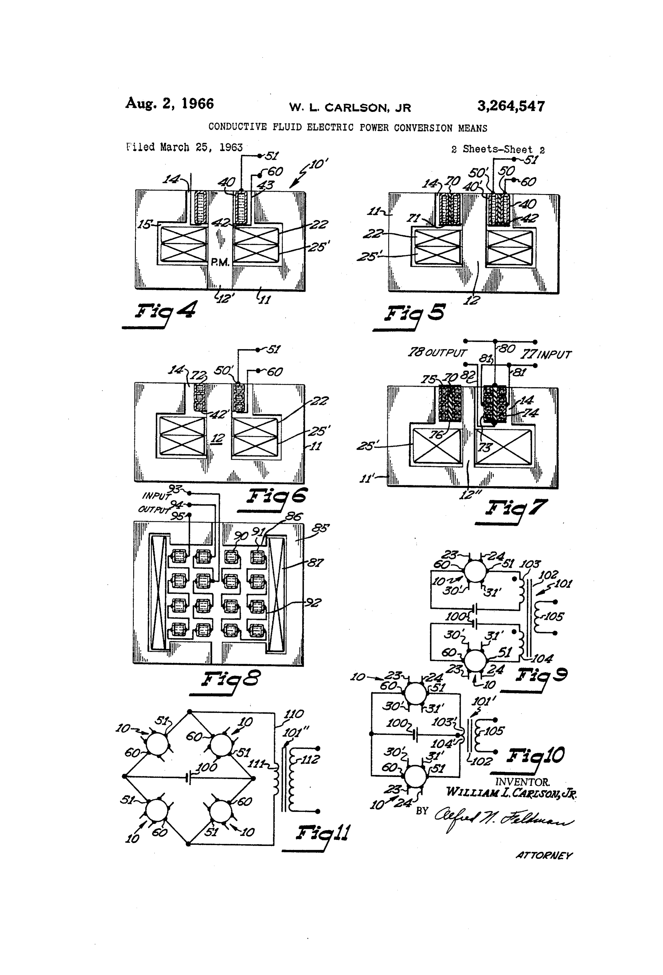
FiGURE 1 is a cross section of a conductive fluid power conversion means utilizing a single annular conductive fluid channel and having a laminated magnetic structure So that the device can be used to convert direct current to alternating current;
FIGURE 3 is an enlarged portion of FIGURE 2 as indi cated by the reference circle in FIGURE 2;
FIGURE 4 is a schematic representation of FIGURE 1. incorporating the addition of a permanent magnet to the magnetic circuit;
FIGURE 5 is a schematic representation of a device similar to that of FIGURE 1, but utilizing two concentric fluid conduits;
FIGURE 6 is a schematic representation of a power con version means utilizing a spiral or helical fluid conduit means;
Page 2drawing sheetscan →
Page 3scan →
Conductive flued electric power
(conversion means
William L. Carlson, Jr., Bloomington, Minn., assignor to 5 Honeywell Inc., a corporation of Delaware
The present invention is primarily directed to a con ductive fluid power conversion means that is capable 10 of converting an exceedingly low voltage, direct current to a more usable level of either direct current or alternat ing current. This invention is an improvement on my Conductive Fluid Power Transformer which is disclosed in Patent No. 3,034,002, which issued May 8, 1962. 5 Considerable work has been done in the field of pow er generation or conversion with conductive fluids, such as the liquid metal known as NaK. NaK is a mixture of sodium and potassium and is one of the more common conductive fluids utilized in present day conductive fluid 20 units. The invention, however, is in no way limited to the use of liquid metal, but may be any type of conductive fluid. The use of electromagnetic flowmeters is one Way of converting power and such meters have been built which develop voltage that is allowed to be dissipated by 25 the return path surrounding the flowmeter walks and in the fluid itself. In some of the more sophisticated de signs, the generated voltage is bucked out and the bucking voltage read as a measure of the flow rate. This type of power convertor has a very limited capacity and is 30 not generally applicable to the problem of converting large currents at low voltage to any more usable form. Conductive fluid pumps discharging into a generating gap of the flowmeter type and returning to the pump have been investigated. A disclosure of this type is in 35 corporated in the above-referenced issued patent. This work has been done by a number of people both in the United States and abroad. The energy level changes and the devices previously considered appear to be quite lim ited and the over-all transfer of work is low enough to 40 result in poor efficiency. One of the main efficiency lim iting factors under certain conditions of load is the en trance and exit eddy current losses. These losses occur even on direct current equipment when the conductive fluid enters or exits from the fields in which the gaps 45 of the device are located. In the pump-generator arrange ment, this occurs four times, once each at each end of the gap. This eddy current loss is actually evident whenever the fluid being circulated experiences a change in flux density with respect to time. This more fundamental 50 limitation imposes the restriction that the fluid velocity and/or the flux density must be such as to maintain a con stant rate of change of flux with respect to time and pref erably this must be equal to zero. Since energy levels can change only when a change occurs from a variation 55 in velocity, flux density, or length of conductor, most of the simple devices previously utilized in this field of en deavor have the combination of eddy current losses that have been described above.
A second major consideration is that of the pumping 60 effect when a generator is connected in a hydraulic loop to a pump. This means that the actual energy conversion is from electrical to hydraulic, and then back again to electrical. Previous work has indicated that the pumping action is less efficient than its generating counterpart, and 65 without careful design, the hydraulic losses in this type of a loop can be excessive.
A third consideration of a conductive fluid armature device that bears a direct influence on the configuration 70 is the interaction of the armature circuit current and the field excitation flux. Work on conductive fluid pumps
Office Patiented August3,264,547 and flowmeters has resulted in the solution to this problem by several means. Regardless of the particular solution utilized, it is normally referred to as "compensation,' and it has become apparent that any configuration of a conductive fluid power converting device must be totally compensated in order to obtain a sufficient efficiency to make a device of this type commercially and economically feasible.
In order to meet the requirements for the most efficient possible power conversion system, the considerations Stated above seem to indicate that the device should have the following characteristics. The fluid as it flowed should experience no change or little change influx density through its entire cycle. The fluid flow should be at the lowest possible velocity commensurate with the re quired conversion requirements of the device. The to tal distance that the fluid travels must be kept to a mini mum. The confining passage must be shaped so as to impose a minimum of hydraulic loss on the unit. The fluid flow passage should be constructed so that there is a minimum of shunting of electric current in the device through the side walls of the unit. With these considera tions in mind, the invention of the present disclosure was developed.
The primary object of the present invention is to dis close a power conversion means utilizing a conductive fluid as the converting medium in which a minimum of loss is provided by having the shortest possible hydraulic route commensurate with the output requirements and one which entails little or no change in magnetic flux through the entire circuit.
A further object of the present invention is to dis close a conductive fluid electric power conversion means that is capable of converting an exceedingly low voltage at a high current into a mere usable form of electrical energy. Yet another object of the present invention is to dis close a power conversion device which is capable of con verting direct current to alternating current, and which utilizes a very minimum amount of alternating current as an operating input.
Another object of the present device is to disclose a conductive fluid power converting device that is capable of converting a direct current potential of an exceedingly low value to a higher level of direct current potential in an efficient way.
Still another object of the present invention is to dis close a power conversion means that is normally energized from a low voltage, high current direct current source and which is capable of isolating the voltage or power to be converted from the output power so as to provide a usable converted electrical energy.
These and other objects will become apparent when the present device is considered along with the drawings, wherein:
FiGURE 1 is a cross section of a conductive fluid power conversion means utilizing a single annular conductive fluid channel and having a laminated magnetic structure So that the device can be used to convert direct current to alternating current;
FGURE 2 is a section of FIGURE 1 taken along line
FIGURE 3 is an enlarged portion of FIGURE 2 as indi cated by the reference circle in FIGURE 2;
FIGURE 4 is a schematic representation of FIGURE 1. incorporating the addition of a permanent magnet to the magnetic circuit;
FIGURE 5 is a schematic representation of a device similar to that of FIGURE 1, but utilizing two concentric fluid conduits;
FIGURE 6 is a schematic representation of a power con version means utilizing a spiral or helical fluid conduit means;
Page 4scan →
S 4.
FIGURE 7 is a schematic representation of a device ously described, an electric coil 22 having leads 23 and utilizing two concentric helical fluid conduits that are elec 24 is placed within recess i5 of the device. A further trically connected for direct current to direct current con group of coils 25, 26, 27, and 28 are also placed in the version; recess 5 and the conductors from coils 25-28 have been FIGURE 8 is a schematic representation of a modifica indicated by the numbers 30-37. Each of the conductors tion of the present invention in which the magnetic circuit 23, 24, and 30–37 are brought out through holes drilled has its air gap located in a different position; and through the laminated structure. In the device actually FIGURES 9, 10, and 11 are three schematic representa constructed and tested, all of the holes were drilled in tions of a conductive fluid electric power conversion sys approximately the same line and all of the conductors were tems utilizing direct current to alternating current power O brought out to an appropriate terminal board, not dis conversion means of the type disclosed in FIGURES 1-6. closed.
The conductive fluid electric power conversion means The cois 25-28 were utilized for convenience and all that is shown in detail in FIGURES 1-3, has been opera of the coils 25–28 could be replaced by a single coil having tionally tested in a push-pull configuration similar to that but a pair of terminals, similar to the coil 22. In the pres disclosed in FIGURE 10. Some of the constructional de ently disclosed device, the coil 22 is connected by conduc tails have been simplified for the present explanation of tors 23 and 24 to a source of alternating current at 60 the design and function of the novel device, and a number cycles (not shown), and the coils 25-28 were energized of various and other configurations of the device have been by their conductors 30-37 from a single source of direct disclosed. current (not shown). With both of the coils 22 and a Since this device can be constructed in many configura group of coils 25-28 energized in this fashion, a magnetic tions and still be within the scope of the present invention, flux was generated in the structure 10 and this flux was the specific unit disclosed in FIGURES 1-3 should be con made up of a first component which is constant due to the sidered as only representative. The device is particularly direct current energization of the coils 25-28, while the adapted for converting exceedingly low potential direct second component was of an alternating nature due to the current into more usable levels. Devices such as fuel 25 energization of coil 22 by alternating current. The effect cells, thermo-electric generators, and solar cells develop an of this energization of the coils 22 and 25-28 was to gen exceedingly low potential that is very difficult to utilize. erate a magnetic flux radially across the air gap 4. This These devices require some conversion system to make the flux can be considered as being of a fixed value which has voltage available more readily adaptable for powering alternations above and below the fixed or reference value. more conventional units. The device disclosed by the 30 In any regard, this magnetic flux can be considered as present invention has been tested at levels as high as 1,900 separable into two distinct components, dependent on the amperes at 0.08 volts direct current input with a nominal mode of creating the flux.
direct current applied to the magnetic field coils for pro Inserted in air gap 14 is an annular conduit 40 that duction of the magnetic field necessary for its operation. is filled with a conductive fluid 41. In this particular The device also utilizes a nominal alternating current that 3 5 case, the fluid was of the type known as NaK, previously would be available from ordinary commercial sources and discussed. The conductive fluid substantially fills the con which provides part of the generated magnetic flux neces duit and the conduit is a closed annular unit. Attached sary to provide the conversion from direct current to alter to the bottom 42 of the conduit 40 is a conductor or nating current. With this background, a full disclosure electrode means 43. In reality, the conductor 43 is a of the structure and operation of FIGURES 1-11 is made. sheet of copper that has been bent into a Z-shape and In FIGURE 1, there is disclosed in cross section a single which has individual segments 44 separated by air spaces conductive fluid power conversion means 10. The conver 45 (FIGURE 2). The separation of the conductor 43 Sion means 10 is made up of two groups of laminated into segments is to prevent eddy current flow in an annular magnetic members 11 and 12. The laminated members 1 fashion through the device and substantially limits any are C-shaped in cross section and are bent to form a curved current flowing in the electrode means 43 to a straight surface. This can be readily seen in FIGURES 2 and 3. line along the Z-shaped cross section of the segment 44. The laminations 2 are a plurality of rectangular members Insulating layers 46 and 47 isolate electrode 45 from that are curved so that they can be stacked together to the air gap 14 and the conduit 40. form an annular magnetic member. When a plurality of Attached to the top 50 of the conduit 40 by any con the laminations 1 are fitted together, they form a corn 50 venient welding or soldering technique is an electrode 5i. pletely circular laminated structure having an air gap 13 The electrode 5 is an annular or washer-like copper and an air gap at 14 with an enlarged recess 15. The member that is in contact with the top 50 of the conduit laminations are assembled in a jig or form and then are means 40, but which is raised from the top of the lami Welded at 16 around the outer periphery to lock the lami nations 2 so as to provide electrical insulation. At nations into a unitary magnetic member. tached to electrode 51 as a further copper electrode 52 A plurality of the laminations 2 are assembled to form that is used for connection of one side of the device to a an annular magnetic core for the device and are placed in high current, low voltage source, and as an output elec the air gap 13 and welded at 17 to lock the laminations 12 trode, as will be seen below. These copper members to the laminations 11 to form the entire magnetic circuit form an electrode means generally for the device. means for the device. With this arrangement, the mag 60 A washer 53, an insulating washer 54, and nuts 55 netic circuit means has the remaining air gap 14 that will along with bolt 56 clamp the device into a unitary struc be described in some detail along with the equipment that ture. The nuts 55 and bolt 56 hold the electrodes 51 is placed in the air gap 14. and 52 in place which, in turn, supports the conductive A central hole 20 is left in the laminations 12 by the fluid conduit 40 in the air gap 14. To complete the elec fashion in which they are assembled and the hole 20 is trical circuit necessary for the device disclosed in FIG lined with an insulating member 21. The insulating mem URE 1, a ring-like electrode 60 is provided around the ber 21 has been shown in an enlarged and exaggerated electrode 51. An air space allows the conductor seg croSS Section. In reality, the insulating member 21 is a ments 44 to be brought up to a recess 6 in the electrode coat of varnish. At the exceedingly low voltages involved 60 where Screws 62 clamp a ring of conductive metal 63 in the present device, certain of the insulating surfaces over the conductor segments 44. The ring 63 is used as that have been shown in exaggerated form as insulating a clamping means to make good electrical contact be members are in fact coats of varnish. It is well known tween the conductor 43 in the form of the segmented that electrical varnish will withstand the nominal voltages members 44 and the electrode 60. In addition to the involved in these areas of the present device. screws utilized for clamping, the device can be soldered During the assembly of the magnetic circuit, as previ or welded to complete the electrical joint.
Page 5scan →
In considering the structure to this point, it should be through the load resistance is also of the same form but noted that an electrical path is provided between the elec is magnified or amplified in its voltage level. The present trode 52 and the electrode 51 where an electrical con device operates in somewhat the same fashion by using nection is made at surface 50 to the conduit 40. The the two components of magnetic flux and the single mag conduit 40 is made of a high resistance metal but allows netic circuit. One flux is used as a main generating flux, good conductivity of the electricity from electrode 51 while the second flux is used as a signal flux to be am across the thin surface 50 into the conductive fluid 4. plified in the device. The output is then taken off through Since the conduit 40 has thin walls, the long or vertical a load device which, in turn, has two components avail sections of the wall form a high resistance path to elec able to it, one being a fixed component supplied by the trical flow as compared to the conductive fluid 41, and the O main power supply, while the other component across bulk of the current flows through the conductive fluid the load is an amplified version of the input signal. If 41 to the lower side 42 of the conduit 40. At 42, the the presently disclosed device is considered as an ampli conductor 43 is connected to conduit 40 thereby complet fier in the same sense that the triode amplifier of the ing an electrical path for current flow from the electrode vacuum tube type is considered, some understanding of 52. The current is then brought out on the conductor 5 the amplification of the current to be converted can be segment members 44 to the electrode 60. It is thus appreciated.
obvious that any current flowing from electrode 52 passes The principle developed in connection with FIGURES into the magnetic structure in the gap 14 through the 1-3 can be applied to many physical configurations. In expedient of the conductive fluid 41 and then passes back order to clarify a number of these possible configurations, out through that same gap by the expedient of the con 20 the device has been shown in schematic form in FIG ductor 43 and the segments 44. This arrangement is to URES 4-8 with variations that can be readily accom provide a full compensation of the magnetic effects created plished within the scope of the present invention. In by the current flow through the conductive fluid. This FIGURE 4, a schematic representation of the device dis expedient is well known in the art and is one of the many closed in FIGURES 1-3 is provided, with slight modifica possible means of compensating a conductive fluid device. 25 tion. Similar numbering will be used so that a corres As previously described, the magnetic structure has pondence will be apparent. In FIGURE 4, a conductive both an alternating current coil and direct current coil fluid power conversion means 16' is provided having lami means to provide a generated magnetic flux. When a high nates 11 in the outer structure, and a center leg 12' which current flows between electrode 52 and electrode 60 of a is in this case a permanent magnet. The permanent direct current nature, the direct current passing through 30 magnet of course could be replaced by laminations of the the conductive fluid 41 reacts with the continuous or type disclosed in FIGURE 1 if an identical configuration direct magnetic flux component to create a conductive to FIGURE 1 is desired. Provided within an air gap 14 fluid pump. This conductive fluid pump then circulates is a coil 22 and a coil 25' which corresponds to the coils the conductive fluid 41 endlessly around the annular con 25-28 of FIGURE 1. A conductive fluid filled channel duit 40. This spinning fluid has a peculiar characteristic. 40 is provided in the annular air gap 4 and is connected This fluid never leaves the magnetic flux field to which it to electrodes 51 and 60. Electrode 60 again has a proper is subjected. Further, the construction is the shortest conductive means 43, which connects the electrode 60 to possible route, being a circle around an annular or circular the bottom 42 of the conductive fluid filled channel 40. device. These requirements meet two of the essential The device disclosed in FIGURE 4 operates in an iden requirements of a conductive fluid electric power conver 40 tical fashion to that disclosed in FIGURE 1, except that sion means that has an efficient output. a permanent magnet is Supplied to supplement the perma If the conductive fluid 41 is considered as spinning, nent magnetic flux generated by the coil 25'. In some due to the influence of the mutually right-angled electric cases the coil 25' might be left out of the device entirely current from the direct current source to be converted and the permanent magnet 2' utilized as the sole flux and the constant magnetic field from the direct current component of a constant nature which is used to generate energized coil, it should be noted that the spinning con the circulating motion in the conductive fluid filled chan ductive fluid 41 is also being cut by an alternating mag nel 40.
netic field established by the coil 22 which has been In FIGURE 5, the disclosed conductive fluid electric connected to an alternating current source. As such, the power conversion means has laminates 1 in the magnetic spinning conductive fluid 41 is cut by an alternating 50 structure with center laminations 12 and coils 22 and magnetic field and thereby generates an alternating elec 25. Again the air gap 14 is provided along with the tric current. This alternating electric current is different electrodes 51 and 60 which, in this case, are connected in form from the current to be converted and is available to two concentric conductive fluid filed conduits 40 and between the electrode 52 and the electrode 60. If some 40'. The conduits 40 and 40' are concentric with one means is provided for filtering this combination of direct 55 another and are separated by an insulating member 70, current and alternating current available on the electrodes again an insulating varnish. The conduits 40 and 40' 52 and 60, it is possible to convert from a high current, are connected at their bottom edges by an electrical con low potential direct current into an alternating current nection means 71 so that electrical current flowing from form. The means of obtaining this isolation is discussed electrode 51 passes into the top 50 of the conduit 40 subsequently in the present specification. 60 and passes to the electrical connection means 75. The The theory of operation of the device disclosed in electrical connection means then connects the current FIGURES 1-3 can possibly be better understood if an flow to the bottom 42 of the conduit 46, where the cur analogy is drawn between the device disclosed in FG rent passes back through the conductive fluid in conduit URES 1-3 and simple vacuum tube triode amplifier. In 40 to the top 50 of the conduit to in turn flow to the elec a simple vacuum tube triode amplifier, a fixed potential 65 trode 6). The difference between the device disclosed is applied by a bias device between the control grid and in FIGURE 5 and that in FIGURE 1 is that the conduc the cathode. The control grid is then supplied with some tor 43 which returns the current adjacent the conduit 40 form of alternating current signal. This alternating cur has been replaced by a second concentric conduit 40'. rent signal turns the triode on and off and allows current This provides for the full compensation of the magnetic flow to pass between the cathode and plate of the ampli 70 fields generated by the current flow between electrodes fier. The voltage between the cathode and the plate is 51 and 60 as they pass into and out of the air gap 14. normally supplied by some fixed voltage source and the With this arrangement, two concentric fluid filled con current flow is normally through some type of load device, duits provide rotating fluid which in turn is cutting the such as a resistor. If the signal supplied to the grid of magnetic field generated by the alternating current flux the amplifier is of an alternating form, the flow of current 75 that has been set up from the coil 22. Again, this pro 6 vides for the conversion and differs from FIGURE 1 nel to the opposite side of the spiral channel. Again, a only in that the compensation means has been replaced complete spiral arrangement has been provided for fluid by a conductive fluid filled channel rather than the mere flow with one spiral 90 within the second spiral 91 and copper conductors. the two interconnected as a series conduit. This pro In FIGURE 6, there is disclosed a conductive fluid vides a rather long fluid flow path that never leaves the electric power conversion means in which the laminations magnetic circuit.
1i and 12 provide the air gap 14 which has placed within The input to the device of FIGURE 8 is supplied be it a closed spiral conduit 72 having three turns. The tween electrodes 93 and 94 which are in turn connected spiral conduit 72 again has electrodes 5 and 60 con to two points on the inside spiral conduit 90. This pro nected respectively to the top 50' and bottom 42 so that O vides for a current flow between the electrodes 93 and 94 the electric current applied between the electrodes 5 and which passes through the conduit 90 at right angles to the 60 passes through the convolutions of the spiral conduit magnetic flux generated by coil 87 across the air gap 86. 72. Coils 22 and 25' are again provided to generate the This forces the fluid to circulate in the continuous spiral necessary components of the magnetic flux across the air fashion and an output potential is derived between the gap 14. The spiral conductive fluid filled conduit 72 is 15 electrode 94 and an electrode 95 that is connected to a closed back on itself to form an endless helical path for point on the conduit 91.
the conductive fluid to circulate within. Since the con It becomes apparent from the discussion of the FIG ductive fluid path in this arrangement is substantially URES 4-8 that many variations of the present invention longer than the previously utilized paths, the voltage can be accomplished. There are endless configurations transformation ratio of the device is changed. This 20 of Spiral or helical types of conduit configurations that change in length of the conduit 72 alters the hydraulic could be placed in the device and which will perform losses of the device, but subjects the flowing fluid to a the power conversion function that is disclosed in the different fraction of the generated magnetic flux on each simple channel of the device disclosed in FIGURES 1-3. turn, thereby accomplishing a change in transformation In order to utilize the power from the conductive fluid ratio. 25 power conversion means, it is necessary to separate the In FIGURE 7, there is disclosed a device which is util alternating and direct current sources from one another. ized for converting direct current to direct current of a Means for accomplishing this are disclosed in FIGURES different level. In this device, a single coil 25' is utilized 9-11. Only the simplest form will be described for ease in a laminated or solid magnetic structure 11’ and 2'. and it is understood that the same structure could be used This structure also could incorporate the permanent mag 30 With the various configurations disclosed without departing net 12 of FIGURE 4 as the center leg. Again an air gap from the present invention.
14 is provided across which a magnetic flux passes. In In FIGURE 9, a simple bucking arrangement is dis corporated in the air gap 14 is a pair of concentric spiral closed. A conductive fluid power conversion means is gaps 73 and 74 which are joined electrically across their Schematically shown at 10 and has alternating current tops at 75 and across their bottoms at 76. These spiral 35 inputs 23 and 24 disclosed at the top while the conduc conduits are separated by insulator 70 into two concentric tors 30' and 31' represent a direct current input to the spiral conduits through which the conductive fluid can coils 25-28 of FIGURE 1. The output of the power flow. By joining the conduits 73 and 74 together at their conversion means is on a pair of conductors marked as top 75 and bottom 76 by electrical conductive devices, 40 electrodes 51 and 60. Each of the power conversion two parallel current paths are provided. The input to means is connected to a source of high current, low volt this device is disclosed at 77, while the output is disclosed age direct current marked as 100. Each of these sources at 78. The input 77 is from any direct current source 100 could be a fuel cell or similar type device that is to be converted and allows the current to flow on conduc capable of generating an exceedingly large current at low tor 80 to the top 75 of the conduits 73 and 74. The potential. A stationary transformer means 101 is dis current splits and flows equally down to an intermediate closed having magnetic core means 102 and a pair of point where it is collected on conductor 81 to return to the input circuit means 103 and 104. The transformer input source. With this arrangement, part of the spiral further has an output circuit means 105. In considering conduits 73 and 74 are utilized to create the movement the operation of the device of FIGURE 9, it will be ap of the enclosed conductive fluid. This movement, since preciated that the current flow between electrodes 51 it is in a pair of spiral gaps, moves the conductive fluid 50 and 60 contains both an alternating current component through the entire gap structure. The movement of the and a direct current component. In transformer means conductive fluid in the air gap 4 causes the generation 10, the current flowing in the input circuit means 103 of an electric potential between the conductor 80 and the and 104 will generate a pair of equal and opposite con bottom 76 of the spiral conduits. The output 78 avail Stant magnetic fields in the core means 102 so that the able between conductor 80 and a conductor 82 is there core means does not become saturated. The input cir fore substantially different than the input to the present cuit means 103 and 104 have been selected and polarized device. As a result, a transformation ratio exists, de So that the flux generated in each of these is opposite to pendent on how far along in the spiral the conductors One another, thereby cancelling each other. The only 81 join into the walls of the spiral configuration. component that passes from the input circuit means 103 In FIGURE 8, an entirely different magnetic structure 60 and 104 to the output circuit means 105 is the alternating has been shown. The showing is distorted to make the current that is available from the device. The arrange presentation simple. In this particular device, a magnetic ment of FIGURE 9 best discloses a simple means of ob circuit 85, having an air gap 86 and energizing coil 87, has taining the alternating current from the conductive fluid been provided. The air gap 86 in this particular case is electric power conversion system wherein two power con in the vertical dimension of the magnetic structure 85 and 65 WerSlon means are used.
a flux can be provided vertically across the air gap 86. In FIGURE 10, a pair of power conversion means 10 Placed in the air gap 86 is a single, spiral conduit with are again disclosed with a battery or direct current 100 two concentric portions 90 and 91 that are electrically and the necessary alternating current and direct current connected by conductors 92 that interconnect the sides of connections which are identical to that of FIGURE 9. the turns of the spiral at mutual right angles to the direc 70 In this arrangement, the devices are connected to a Sta tion of the flux generated in the device. Insulated lami tionary transformer means 10' that has a tapped input nated members (not shown for the sake of clarity) sepa circuit means 103 and 104". The operation of this device rate the turns of the channel to complete the magnetic is normally referred to as a push-pull type unit and structure. This flux flows across the air gap 86 with the Operates on the principle of alternately causing current to conductors 92 connected from one side of the spiral chan 75 flow in the two input circuit means 103 and 104. Since 7 the input circuits 103' and 184' are arranged with a center of said magnetic flux causing said conductive fluid to tap, it is possible to have alternate current flow through circulate through said conduit means in an endless the two halves of the device, thereby causing a cancella fashion; and said moving fluid and a second component tion of any constant magnetic field in core 102 that might of said magnetic flux generating an electric current out be generated and thereby the transformation of only the put between said electrode means to provide an electric alternating current available is provided. current different from that of said electric current to be In FIGURE 11, a bridge configuration of units has converted.
been disclosed in simplified form. The power conver 3. A conductive fluid electric power conversion means sion means 10 have had their output electrodes designated including: magnetic circuit means having an annular as 51 and 60. The power conversion means 16 have been 0. air gap; magnetic flux generating means including a pair hooked in a conventional bridge configuration with a of electric coil means associated with said magnetic direct current power source 100 to be converted across circuit means to generate a magnetic flux radially across one leg of the bridge and the transformer means iO, said air gap; a first of said coil means connected to a connected across the other leg of the bridge. In this direct current source and a second of said coil means configuration, there is no need to buck out the constant 5 connected to an alternating current source to thereby magnetic field that would be generated by the direct cur generate said magnetic flux; closed fluid conduit means rent flow, as the bridge arrangement inherently causes filled with a conductive fluid and located in said air gap; the direct current to flow only in the center leg where electrode means connected to said conduit means to con the battery 100 is located. The alternating current flows duct a direct current to be converted through said con in conductor A10 and passes from the input circuit means 20 ductive fluid at mutually right angles to said magnetic 111 to the output circuit means 12 thereby providing a flux generated by said first coil means and a fluid flow usable alternating current as the devices output. direction of said fluid conduit means; said direct current The disclosure of FIGURES 9, 10, and 11 are of three and said magnetic flux generated by said first coil means possible arrangements to utilize the power conversion causing said conductive fluid to circulate through said means in a power conversion system thereby eliminating 25 conduit means in an endless fashion; and said moving the direct current that normally would flow in the output fluid and said magnetic flux generated by said second of the device. These configurations are representative coil means generating an alternating current output be only of three possible ways and others would become tween said electrode means to provide an electric current apparent to one skilled in the art. different in form from that of said direct current to be The applicant has disclosed a very basic concept for 30 converted.
utilizing electric power that is otherwise of a level that 4. A conductive fluid electric power conversion means, could not be readily utilized. The power conversion including: magnetic circuit means including a permanent means themselves disclosed in FIGURES 1-8 are typical magnet portion and said circuit means having an an of various configurations that are possible, but in no nular air gap; magnetic flux generating means including way are limitations of the many other possible configura 35 electric coil means associated with said permanent mag tions that would be obvious to one skilled in the art. net in said magnetic circuit means to generate a magnetic The conversion systems of FIGURES 9-11 also are flux across said air gap; closed fluid conduit means filled merely representative of preferred embodiments and are with a conductive fluid and located in said air gap; elec by no means meant to be limitations on the ways of utiliz trode means connected to said conduit means to conduct ing the output of the power conversion means in systems. 40 an electric current to be converted through said con The disclosures, having been made of the preferred em ductive fluid at mutually right angles to said permanent bodiments, constitute no limitation on the scope of the magnet magnetic flux and a fluid flow direction of said present invention, and this scope is defined only in the fluid conduit means; said current and a first component scope of the appended claims. of said magnetic flux including said permanent magnet I claim as my invention: 45 flux causing said conductive fluid to circulate through 1. A conductive fluid electric power conversion means, said conduit means in an endless fashion; and said mov including: magnetic circuit means having an annular ing fluid and a second component of said magnetic flux air gap; non-rotating magnetic flux generating means generating an electric current output between said elec associated with said magnetic circuit means to generate trode means to provide an electric current different from a magnetic flux that is stationary in space across said air 50 that of said electric current to be converted. gap; closed fluid conduit means filled with a conductive 5. A conductive fluid electric power conversion means, fluid and located in said air gap; electrode means con including: laminated magnetic circuit means having an nected to said conduit means to conduct an electric cur annular air gap: electric coil means associated with said rent to be converted through said conductive fluid at magnetic circuit means to generate magnetic flux across mutually right angles to said magnetic flux and a fluid flow said air gap; closed fluid conduit means filled with a direction of said fluid conduit means; said current and a conductive fluid and located in said air gap; electrode first component of said magnetic flux causing said con means connected to opposite sides of said conduit means ductive fluid to circulate through said conduit means in to conduct a direct current to be converted through said an endless fashion; and said moving fluid and a second conductive fluid at mutually right angles to said generated component of said magnetic flux generating an electric 60 magnetic flux and the circumference of said fluid conduit; current output between said electrode means to provide Said direct current and a first component of constant flux an electric current different from that of said electric of said magnetic flux causing said conductive fluid to current to be converted. circulate around said conduit in an endless fashion; and 2. A conductive fluid electric power conversion means, Said moving fluid and a second component of said mag including: magnetic circuit means having an annular 65 netic flux generating an electric current between said elec air gap; non-rotating magnetic flux generating means in trode means to provide an electric current different from cluding electric coil means associated with said magnetic that of said direct current to be converted. circuit means to generate a magnetic flux that is stationary 6. A conductive fluid electric power conversion means, in space across said air gap; closed fluid conduit means including: a laminated magnetic circuit having an annu filled with a conductive fluid and located in said air gap; 70 lar air gap; magnetic flux generating means including a electrode means connected to said conduit means to con pair of electric coil means associated with said magnetic duct an electric current to be converted through said circuit to generate a magnetic flux radially across said conductive fluid at mutually right angles to said gen air gap; a first of said coil means connected to a direct erated magnetic flux and a fluid flow direction of Said 75 current source and a second of said coil means connected fluid conduit means; said current and a first component to an alternating current source to thereby generate said 8 magnetic flux; an annular fluid conduit filled with a con air gap; magnetic flux generating means including a pair ductive fluid substantially filling said air gap; a pair of of electric coil means associated with said magnetic cir electrodes connected to opposite sides of said conduit to cuit means to generate a magnetic flux radially across conduct a direct current to be converted through said said air gap; a first of said coil means connected to a conductive fluid at mutually right angles to said magnetic direct current source and a second of said coil means flux generated by said first coil means and a circumfer connected to an alternating current source to thereby ential fluid flow direction of said fluid conduit; said di generate said magnetic flux; closed fluid conduit means rect current and said magnetic flux generated by said filled with a conductive fluid and located in said air gap; first coil means causing said conductive fluid to circulate said conduit means being helical in form and substantial through said conduit in an endless fashion; and said mov O ly filling said air gap; electrode means connected to said ing fluid and said magnetic flux generated by said Second helical conduit means to conduct a direct current to be coil means generating an alternating current output be converted across the turns of said helix with said conduc tween said pair of electrodes to provide an electric cur tive fluid at mutually right angles to said magnetic flux rent different in form from that of said direct current to generated by said first coil means and a fluid flow direc be converted. tion of said fluid conduit means; said direct current and 7. A conductive fluid electric power conversion means, said magnetic flux generated by said first coil means caus including: a laminated magnetic circuit having an an ing said conductive fluid to circulate through said con nular air gap; magnetic flux generating means including duit means in an endless spiral fashion; and said moving a pair of electric coil means associated with said mag fiuid and said magnetic flux generated by said second coil netic circuit to generate a magnetic flux radially across 20 means generating an alternating current output between said air gap; a first of said coil means connected to a di said electrode means to provide an electric current dif rect current source to be converted and a second of Said ferent in form from that of said direct current to be coil means connected to an alternating current Source to converted.
thereby generate said magnetic flux; an insulated annu 50. A conductive fluid electric power conversion lar fluid conduit filled with a conductive fluid substan 25 means, including: magnetic circuit means having an an tially filling said air gap; a pair of electrodes connected nular air gap; magnetic flux generating means including to opposite sides of said conduit to conduct said direct electric coil means associated with said magnetic circuit current to be converted through said conductive fluid at means to generate a magnetic flux radially across said mutually right angles to said magnetic flux generated by air gap; said coil means connected to a direct current said first coil means and a circumferential fluid flow di source to thereby generate said magnetic flux; closed fluid rection of said fluid conduit; one of said electrodes pass conduit means filled with a conductive fluid and substan ing through said air gap adjacent said conduit to mag tially filling said air gap; said conduit means being helical netically compensate said magnetic circuit; said direct in form with two concentric helical portions; electrical current and said magnetic flux generated by said first coil 3 connection means joining said portions at their inner and means causing said conductive fluid to circulate through outer edges to form two parallel electrical paths; elec said conduit in an endless fashion; and said moving fluid trode means connected to said conduit means to conduct and said magnetic flux generated by said second coil a direct current to be converted through at least a por means generating an alternating current output between tion of said conductive fluid at mutually right angles to said pair of electrodes to provide an electric current dif said magnetic flux generated by said coil means and a ferent in form from that of said direct current to be 40 fluid flow direction of said helical fluid conduit means; converted. said direct current and said magnetic flux generated by 8. A conductive fluid electric power conversion means, said coil means causing said conductive fluid to circulate including: magnetic circuit means having an annular air through said conduit means in an endless spiral fashion; gap; electric coil means associated with said magnetic cir and said moving fluid and said magnetic flux generated cuit means to generate magnetic flux radially across said by said coil means generating an electrical output be air gap; a pair of electrically insulated concentric fluid tween said electrode means to provide an electric cur conduits filled with a conductive fluid and located in saidrent different in form from that of said direct current air gap; electrical connection means joining said con to be converted.
duits at an inner edge, electrode means connected to 50 outer sides of said conduits to conduct an electric cur References Cited by the Examiner rent to be converted through said conductive fluid of UNITED STATES PATENTS both conduits at right angle to said generated magnetic 2,113,393 4/1938 Bierwirth --------- 330-195X flux and the circumferences of said fluid conduits; said current and a first component of said magnetic flux caus 55 2,710,312 6/1955 Hafler et al. ------ 330-195 X ing said conductive fluid to circulate around said con 3,034,002 5/1962 Carlson ------------- 310-11 duits in an endless fashion; and said moving fluid and a second component of said magnetic flux generating an JOHN F. COUCH, Primary Examiner.
electric current between said electrode means to provide an electric current different from that of said electric LLOYD MCCOLLUM, Examiner.
current to be converted. 60 9. A conductive fluid electric power conversion means, W. H. BEHA, Assistant Examiner. including: magnetic circuit means having an annular
Provenance
- Collection
- Patents citing this work
- Pages
- 8
- Method
- pdftotext (the PDF's own text layer) + pdftoppm 300dpi page scans
- Patent office record
- patents.google.com →
- Source
- Google Patents citing-documents table
- Assignee
- Honeywell Inc
- Published
- 1966-08-02
- Transcribed from
- patentimages.storage.googleapis.com →