

patent · US3341726A
Rotating bearing contacts for electrical commutators
12 September 1967
Text
Drawings
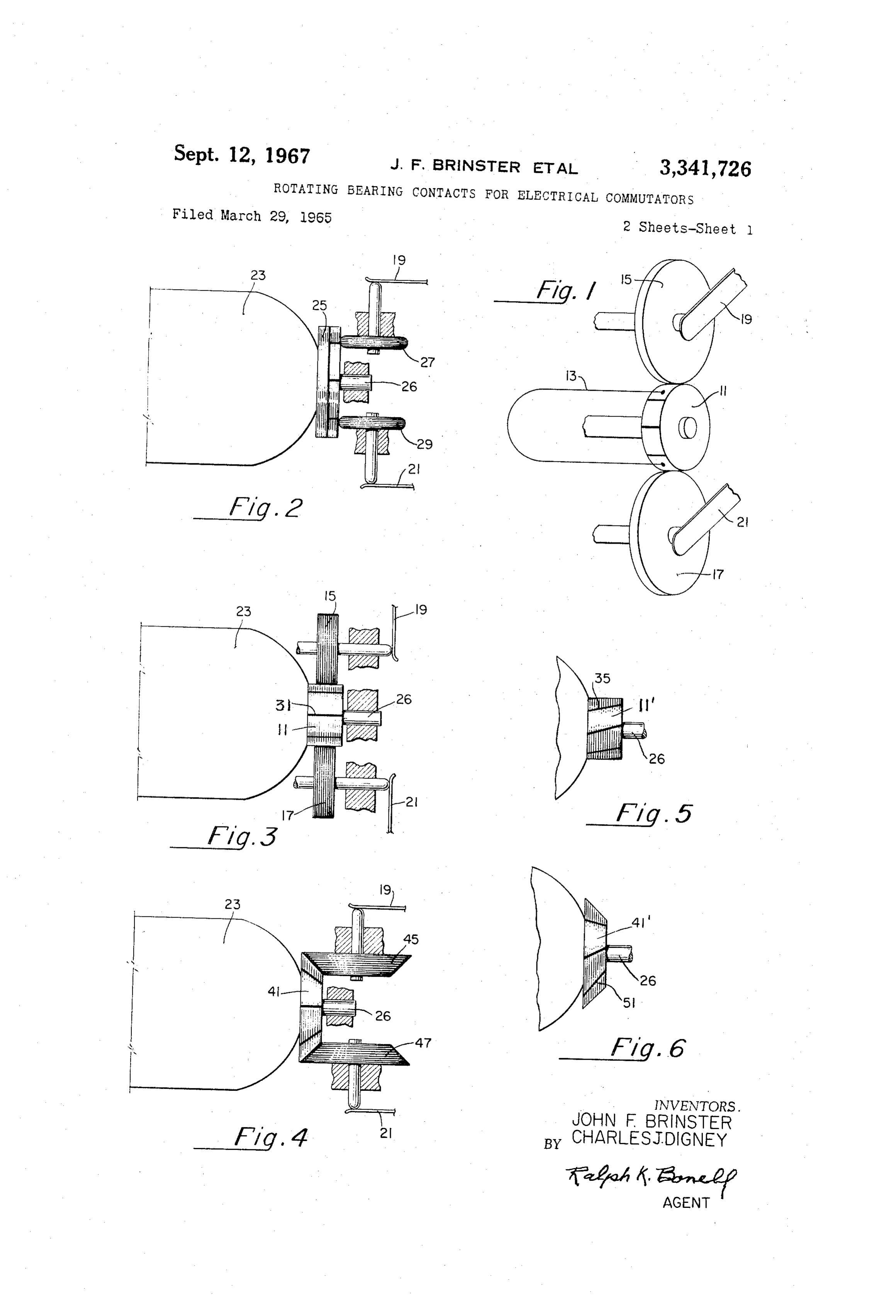
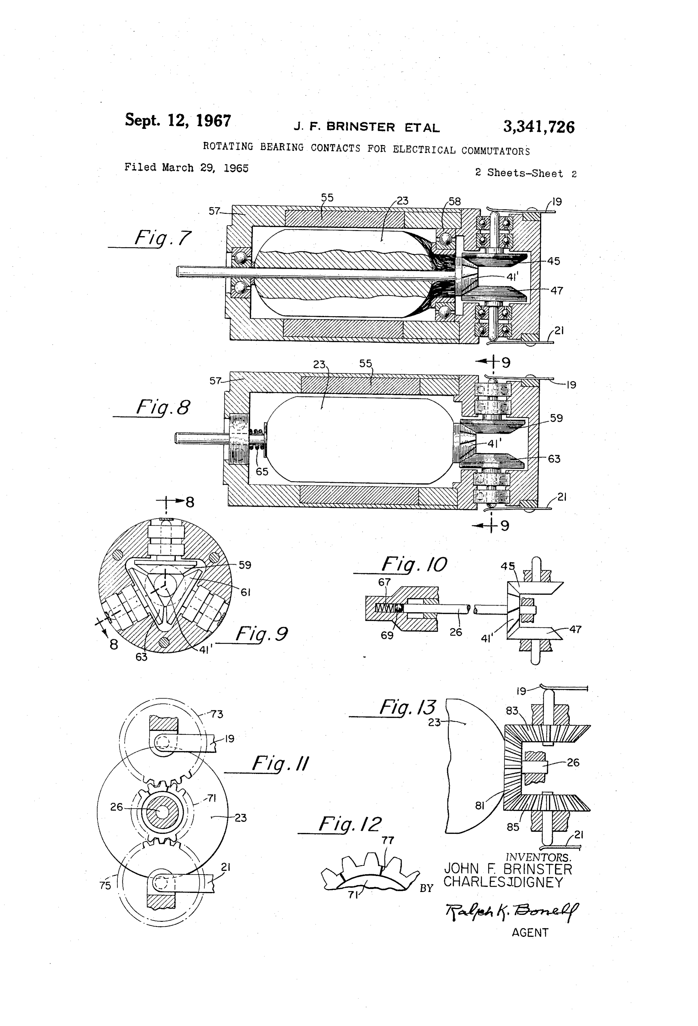
FIG. 10 is a view of a motor or generator armature 35 4 are Surfaces of revolution with respect to their axes of shaft mounting a conical commutator resiliently biased rotation.
Page 1drawing sheetscan →
Page 2drawing sheetscan →
Page 3scan →
United States Patent Office Patented Sept.3,341,726
3,341,726 brushes, results in an increase in the rate of change of
ROTATING BEARNG CONTACTS FOR Spring pressure as this more rapid wear occurs. Another ELECTRICAL COMMUTATORS undesirable effect of strong spring pressure where very John F. Brinster, Princeton, and Charles J. Digney, Small motors are concerned, for example motors designed Kenda: Park, N.J. to deliver less than an ounce-inch of torque, is the loss in Filed Mar. 29, 1965, Ser. No. 443,572 torque it causes over and above the unavoidable loss 2 Claims. (C. 310-90) due to the use of brushes under even light spring pressure. This loss, moreover, is a variable quantity.
The present invention by making use of an electrically
ABSTRACT OF THE DISCLOSURE 10 conductive rotating member or members, or of members There are described various arrangements of rotatable having an electrically conductive surface, in substantially members in rolling contact with a commutator, for ex pure rolling contact with the surface of a commutator ample the commutator of a motor or generator, as sub as a means for conducting current to or from a rotating stitutes for brushes in rubbing contact therewith. In one armature avoids the cited and other disadvantages of arrangement a plurality of rotatable members in rolling 5 sliding brush contacts. The invention is disclosed herein contact with a commutator in addition to providing an as variants of two principal design modifications, these electrical connection or connections constitutes a bearing modifications involving, respectively, the rolling of smooth which replaces a shaft bearing. surfaces of revolution on one another and the rolling action, without sliding, that occurs between meshed gear 20 teeth of suitable contour, the teeth in this case being
This invention relates primarily to means for supplying formed respectively, in the surfaces of the commutator current to the rotating armature of an electric motor or and the rotatable contact member or members. receiving current from the rotating armature of an electric In contrast to the conduction of current between mem generator by way of a segmented commutator, but is bers in pure rolling contact, as disclosed herein, devices not limited to use in connection with such machines. In 25 are known in which the transmission of rotary motion particular it refers to the use of rotatable electrically con inherently also involves sliding action. This is due to the ductive members in rolling contact with the surface of a fact that during rotation portions of the surface of one Emutator in place of brushes in sliding contact there engaged member (commutator or rotatable contact) have with. a linear velocity different than that of the engaged por The conventional arrangement in a motor, for example, 30 tions of the surface of the other member, as a result of brushes spring-biased to sliding contact with a commu of the form and mounting of the members. This inherent tator has a number of known disadvantages. Some of sliding makes these devices subject to the disadvantages these are especially prominent in the operation of motors that have been enumerated in connection with sliding of Small size which are required to supply only a slight brushes.
driving torque but which must operate satisfactorily in It is, then, an object of the invention to provide means the presence of shock or vibration. Motors driving air for conducting electrical current between a stationary borne telemetry equipment are in this category. member and a rotating segmented commutator by way An unavoidable consequence of the use of brushes in of a rotatable conductive member in continuous electrical sliding contact with a commutator is brush wear. In 40 contact with and rotated by the commutator, Substantially small motors which are inaccessible for inspection or through rolling action, only.
maintenance this may be a factor of considerable impor Another object is to provide means for conducting cur tance. Brush wear appears to be a result not only of the rent between a stationary member and a rotating con mechanical rubbing involved but also of the current carry mutator which avoids the use of a member in total ing function of the brush and is accelerated by arcing at 45 or partial sliding contact with the commutator. the commutator. One harmful feature of brush wear is Another object is to provide in an electric motor or that the abraded brush particles tend to adhere to the generator means for supplying current to or receiving commutator. Particularly when metal brushes are used, current from a rotating armature which comprises a seg these particles may form short circuits between adjacent mented commutator and a rotatable electrically conduc commutator segments. With metal brushes another possi 50 tive member in continuous substantially pure rolling con bility under some conditions is welding between the brush tact with the surface thereof. and commutator. In the case of graphite brushes a bad Another object is to provide means of the foregoing feature, for certain applications, is the fact that brush character in which the rolling surfaces of the commutator wear (and the chance of complete brush disintegration) is and cooperative rotatable contact member are smooth markedly increased during operation under low atmos 55 surfaces of revolution.
pheric pressure, as at high altitudes. Another object is to provide means of the foregoing In addition to wear, an aspect of conventional brush character in which the surfaces of the commutator and arrangements that becomes of importance when a motor, cooperative rotatable contact member each comprises a for example, is subject to shock or vibration is the fact toothed portion, said toothed portions being in mesh with that the combination of a displaceable brush and a biasing one another and adapted to transmit motion from the spring therefor constitutes an oscillatory system. There is 60 commutator to the rotatable member with Substantially thus a tendency, due to the inertia of the brush, for pure rolling contact therebetween.
relative vibration to occur between the brush and com Another object is to provide in an electric motor or mutator. The result is a variable contact resistance be generator means for supplying current to or receiving tween these two members that is reflected as a variation 65 current from a rotating armature and commutator which in the voltage applied to the motor armature, which, in comprises a rotatable electrically conductive member in turn, gives rise to a variation in the speed of the motor. continuous substantially pure rolling contact with the Under severe mechanical excitation of the motor a brush commutator and biased at a substantially constant pres may, momentarily, completely leave the commutator. Sure, thereagainst.
A partial remedy for brush vibration is the use of a 70 A further object of the invention is to provide a bear strong spring pressure. This, however, not only increases ing for a rotatable armature and commutator of an elec brush wear but, particularly in the case of graphite tric motor or generator constituted by rotatable conduc 4 tive members in rolling contact with the commutator As an equivalent means, caged rotatable balls (not illus which have the added function of conducting current to trated) may replace the contact wheels. or from the commutator and armature. FIG. 3, in which the members shown correspond gen These and other objects and advantages of the inven erally, in form and arrangement to those in the schematic tion will be more clearly apparent from consideration of of FIG. 1, particularly illustrates the use of cylinders to the following specification describing preferred forms Secure line, instead of point, contact between the com which the invention may take, and from consideration of mutator and contact wheels, while maintaining pure roll the appended drawings in which: ing action. The engaged surfaces of cylindrical commu FIG. 1 is a schematic drawing showing a commutator tator 11 and conductive cylindrical contact wheels 15 for a motor or generator with an armature coil connected 0 and 17 are smooth surfaces. The segmentation of com thereto and with contact wheels in rolling contact there mutator 11 is by means of insulation-filled slots, as slot with, in accordance with the principles of the invention; 31, extending in the direction of the axis of armature FIG. 2 is a partial view of a motor or generator com shaft 26. Certain advantages relative to this arrangement prising a flat-surface commutator with contact wheels in are obtained by skewing the slots, as illustrated in FIG. 5 rolling contact therewith; by slot 35 in commutator 11'. For one thing, this avoids FIG. 3 is a similar view of a motor or generator com driving irregularities as the slots pass beneath the con prising a cylindrical commutator with cylindrical con tact wheels. Moreover, with skewed slots a contact wheel tact wheels in rolling contact therewith; short circuits adjacent commutator segments over a small FIG. 4 is a similar view of a motor or generator com angle of commutator rotation. This is the effect obtained prising a conical commutator with conical contact wheels 20 in a conventional designs by making the bearing surface of brush wider than the slot width.
in rolling contact therewith; Instead of employing rolling cylinders, line contact be FIG. 5 is a partial view of a rotatable armature and tween Smooth surfaces can be attained through the use a cylindrical commutator therefor comprising skewed in of rolling cones. This design, as applied to the present sulating slots between the commutator segments;
FIG. 6 is a partial view of an armature and a conical 25 invention, is illustrated in FIG. 4. Here conical com commutator having skewed slots; mutator 41 has bearing on it, and frictionally drives, FIG. 7 is a view, partly in section, of a complete conical contact wheels 46 and 47. The commutator motor assembly comprising a conical commutator and slots may either extend along elements of generation of conical contact wheels in rolling contact therewith; the cone of which the commutator is a frustum, as seen FIG. 8 is a sectional view of a motor, taken as indicated 30 in FIG. 4, or be skewed in relation thereto as seen in by line 8-8 of FIG. 9, in which conical contact wheels FIG. 6 for slot 51 of commutator 41'. For pure rolling form a bearing for the commutator; action the axes of the conical contacts must intersect the FIG. 9 is a sectional view taken as indicated by line axisBoth of the commutator, the cylinders of FIG. 3 and the cones of FIG.
FIG. 10 is a view of a motor or generator armature 35 4 are Surfaces of revolution with respect to their axes of shaft mounting a conical commutator resiliently biased rotation.
against conical contact wheels in rolling contact there FIG. 7 is a more complete showing of a motor utilizing with; the described arrangement of rolling cones for delivering FIG. 11 is a partial end view of a motor or generator electrical power from a stationary source to the arma armature and a shaft therefor bearing a cylindrical toothed 40 ture. In this desgin 55 is a permanent magnet field while surface commutator, together with cylindrical toothed sur numeral 57 designates the non-ferrous frame of the ma face contact wheels meshed therewith; chine. Commutator 41' has the skewed slots of FIG. 6. FIG. 12 is a detail of FIG. 11, to an enlarged scale; The motor design shown in FIGS. 8 and 9 incorporates and minor changes in the design of FIG. 7 but ones which FIG. 13 is a partial view of a motor or generator com 45 have distinct advantages in certain applications. One such prising a conical toothed surface commutator and conical variation is that instead of two conical contact wheels toothed surface contact wheels meshed therewith. three are used, equally spaced about the commutator. Referring, now, to the figures, FIG. 1 is a schematic These wheels, 59, 61 and 63, thus are adapted, in addi drawing generally illustrating the principal concept of the tion to any current carrying function they may have, to invention. There is shown a rotatable commutator 11 hav 50 constitute a rotative Support or bearing for commutator ing a surface comprising spaced electrically conductive 4of armatureand associated armature 23 which takes the place shaft bearing 58 of FIG. 7. The three-mem segments to which the armature coils of a motor or gen ber bearing arrangement furnishes restraint against rotor erator are connected, as coil 13. Commutator 11 is in contact with and rotatably drives contact wheels or discs or armature acceleration in all directions normal or per 15 and 17 which have uninterrupted or continuously elec 55 pendicular to the rotational axis. Then, too, FIG. 8 shows a loading Spring 65, which maintains a pre-selected pres trically conductive contact surfaces. Contact springs 19 Sure between commutator 41' and wheels 59, 61 and 63. and 21, respectively in electrical connection with these surfaces, provide connections to stationary means, as, in This use of a loading spring exerting a force along the the case of a motor, to a power source. axis of the armature shaft is not limited, however, to the FIGS. 2-4 illustrate the invention in more practical 60 case where the contact wheels form a bearing for the form, particularly that principal modification thereof armature.example,
In the fragmented showing of FIG. 10, for the force exerted by spring 67 on armature which involves the rolling of one smooth surface of revo lution on another. In FIG. 2, motor or generator armature shaft 26 by Way of ball 69 also maintains a selected bias ing pressure between the conical commutator 41' and the 23 has electrical connections to flat surface commutator 25. Electrically conductive contact wheels 27 and 29 rotat 65 two conical contact wheels 45 and 47, these co-acting members being in the relationship seen in FIG. 7.
able about axes perpendicular to that of the armature shaft bear on and are rotatably driven by the commu One design consideration that is pertinent to all the tator. To avoid sliding action due to differences in the arrangements of FIGS. 2-9 is the choice, for the driving linear velocities of the engaged surfaces, the wheels bear commutator and the driven contact wheels, of materials on the commutator at one distance, only, from the axis 70 that have a suitable coefficient of friction, relative to one of rotation of the commutator. This is accomplished by another, to ensure substantially pure rolling action in rounding or beveling their contact surfaces. Hence, only their operation. With a copper alloy commutator the use point contact is made between the two contacting mem of a graphite composition material (available with the bers, which limits their current carrying capacity. The required properties) for the contact wheels affords a advantages of this design are its simplicity and low cost. 75 satisfactory combination when used under suitable COIl 5 ditions. The slight (and otherwise unobjectionable) gra What is claimed is:
phitic coating that the commutator acquired therefrom is 1. In an electric motor the combination of an arma an added advantage in that it serves as a protection from ture and a commutator in electrical connection with the the effects of a corrosive atmosphere. windings thereof, a shaft mounting said two members for Besides the described contact arrangements making 5 rotation about the axis thereof, said shaft having a bear use of the rolling of one smooth surface on another, a ing in direct contact therewith only at the end thereof second principal modification of the invention makes use remote from said commutator, said commutator being of the rolling on one another of meshed gear teeth formed of conical form in coaxial relation with said shaft and in the surfaces of those members by way of which an having a peripheral surface comprising spaced electri electrical connection is maintained. Rolling of one tooth 10 cally conductive segments, a plurality of conical mem surface on another is inherent in the driving engagement bers greater than two rotatable about the axes thereof of suitably meshed gears having teeth of involute form, and respectively positioned for rolling contact between for example. Here, again there is line contact between the the peripheral surfaces thereof and said commutator sur engaged surfaces to supply current carrying capacity and face at equally spaced angular locations about the latter in this case a positive drive without reliance on friction 5 surface, thereby to form a rotative bearing for the com to avoid slippage. mutator and armature in lieu of a second shaft bearing, FIG. 11 shows, as an end view, a cylindrical com the said peripheral surface of at least one of said contact mutator 71 in the surface of which gear teeth are formed, members being continuously electrically conductive, and together with toothed contact wheels 73 and 75 meshed means for conducting electric current from a stationary therewith. The commutator slots in this design prefer 20 source to said last-named surface of the further conduc ably occur in portions of the commutator surface that do tion thereof to the commutator and armature windings. not take part in the engagement of the teeth. As an ex 2. The combination defined in claim 1 wherein the ample, in the enlarged view of FIG. 12 slot 77 is located number of said plural conical members is three and in the trough between two adjacent teeth. The engaged wherein the axes of rotation of all such members inter teeth may have any pitch and may be cut in accordance 25 sects the axis of the conical commutators. with any suitable type of gearing. Thus, they may be straight teeth, that is teeth extending in the direction of References Cited the axis of rotation of the member in which they are cut UNITED STATES PATENTS or, for smoother operation, they may have a helical ex 120,057 10/1871 Gramme et al. 310-219 XR tent. 30
Analagous to the rolling cones of FIG. 7 and pos 399,329 3/1889 Heywood ---------- 310-219 sessing certain of the advantages thereof, bevel or miter 520,152 5/1894 Welch ------- 310-219 XR gearing provides still another means for securing rolling 832,353 10/1906. White ------------- 310-219 action with line contact between contact wheel or wheels 1,375,161 4/1921 Landers ----------- 310-219 and commutator. This is illustrated by FIG. 13. In simi 35 1999,303 4/1935 Sarbey ------- 310-219 XR lar manner to the skewing of the commutator slots in 2,275,827 3/1942. Plensler - 310-219 XR FIG. 6, the teeth of commutator 81 and contact wheels FOREIGN PATENTS 83 and 85 instead of extending along elements of genera tion of the conical surfaces of these members, as shown 207 1870 Great Britain. in FIG. 13, may be skewed relative thereto, with the 40 1,065,579 5/1954 France.
commutator slots similarly skewed.
The disclosure herein of various forms which the in MILTON O. HIRSHFIELD, Primary Examiner. vention may take is not intended to limit the scope of D. F. DUGAN, Assistant Examiner.
the invention, which is fully set forth in the following claims.
Provenance
- Collection
- Patents citing this work
- Pages
- 5
- Method
- pdftotext (the PDF's own text layer) + pdftoppm 300dpi page scans
- Patent office record
- patents.google.com →
- Source
- Google Patents citing-documents table
- Assignee
- John F Brinster
- Published
- 1967-09-12
- Transcribed from
- patentimages.storage.googleapis.com →