

patent · US3403965A
Gas-fired infrared burner
1 October 1968
Text
Drawings
Page 1drawing sheetscan →
Page 2drawing sheetscan →
Page 3scan →
United States Patent Office 2
Patented Oct. 1, 1968
In order to avoid the production of the toxic gases.
3,403,965 mentioned above, attempts have been made to design in
Gas-fired infrareed burner
Adam A. Dreisziger, Lakewood, Ohio, assignor to Bett. frared heaters wherein a direct flame impingement is cher Manufacturing Corporation, Cleveland, Ohio 5 avoided. However, these designs are usually plagued by an undesirable loss of radiant efficiency. This is generally
Filed May 25, 1966, Ser. No. 552,922 due to the cooling of the gases and of the flames before 4 Claims. (Cl. 431-347) proper heat transfer can be made to the radiant element which results in most cases from the use of secondary
ABSTRACT OF THE DISCLOSURE air introduced directly into the combustion chamber to A gas-fired infrared generator is provided for use in 10 achieve fined for complete combustion. Secondary air will be de present purposes as air supplemental to that air connection with space heating installations. The generator in the fuel-air combustion mixture which is introduced is adapted for use without need for ventilating equipment into the combustion chamber when the fuel-air mixture to exhaust the products of combustion. Greater heating is below a combining ratio in order to achieve a more efficiency is afforded by utilizing a wedge-shaped internal 5 complete combustion. Due to the difficulty in mixing sec deflector which is heated to incandescence and which di ondary air in which the gaseous fuel-air mixture, an rects the gaseous products of combustion laterally out amount of air which exceeds the combining ratio is usually Wardly through a perforate incandescent mantle. required. This results in a cooling of the flames and in usa.crip some cases a premature extinguishing of the flames be- . The present invention relates to infrared space heat 20 fore they have reached an optimum combustion condi ing and more particularly to infrared radiantheaters of tion. Accordingly, the use of secondary air is generally undesirable where an optimum radiant efficiency is de metallic construction utilizing the combustion of fuel gas sired.
as their source of thermal energy. Another factor which reduces radiant efficiency in in The use of radiant energy for space heating affords many unique advantages and is particularly useful for 25 stances wherein a direct flame impingement is avoided is the thermal loss due to convection and conduction many applications where other more conventional heat which prevent a sufficient portion of the thermal energy ing methods are not suitable. Large industrial work areas from being transferred from the radiant element. having high ceilings are a particular example as are work Accordingly it is desirable to minimize ventilation and areas where the presence of dust and other deleterious materials makes the use of forced air systems impractical. 30 to dilution of the gaseous products of combustion in order utilize the thermal energy therein in the heating of the
The thermal energy genearted by these radiant heating radiant
Systems is in the form of infrared radiation emitted by a secondaryelement. It is also desirable to avoid the use of high temperature element which is generally formed of combustionairchamber by introducing a fuel-air mixture into the which is as close to a combining metal or a ceramic material and which is heated to a suit 35 ratio as possible, the fuel and air being sufficiently mixed able temperature by an internal heat generator such as to achieve complete combustion electrical heating elements or a fuel gas burner. The pres gas remains. The flame layer in so that no unburned fuel the combustion chamber ent invention relates only to those types of infrared should be spaced sufficiently from heaters which utilize a fuel gas burner to generate the re and other metal parts being heatedtheso radiantthat elements the "flames
Aparticular problem inherent in the use of fuel gas 40 do not impinge directly upon any metallic parts. Addi tionally to generate energy for heating enclosed spaces is the that thermal the heater should be so designed and insulated production of gaseous combustion products some of be kept to alosses due to convection and conduction will minimum.
which under certain conditions may be toxic and endanger Prior gas fired heaters of all-metallic construction have persons in the enclosed heated space if they are not elimi been unable to accomplish these goals and have, in fact, nated. In the case of incomplete combustion caused by an 45 required either the use of secondary air to achieve com insufficient supply of oxygen in the combustion chamber, plete combustion or have used a flue to vent the gaseous carbon monoxide and unburned fuel gas are particular combustion products out of the enclosed heated space. examples and where they are produced in significant con The heater construction of the present invention, how centrations, precautions must be taken to insure that all the gaseous combustion products are forced out of the 50 ever, satisfies the above objections and also provides unique and unexpected advantages heretofore not obtain enclosed space. This ventilation results in the escape of able.
a substantial portion of the available heat energy and also According to my invention there is provided an infra necessitates the installation of expensive fans and ven red generator having a mixer tube for introducing a gase tilating equipment. ous fuel-air mixture into a plenum at an optimum com Even where a more complete combustion is achieved, d bining toxic concentrations of carbon monoxide can be produced coveredratio, by a the plenum having an upwardly facing outlet horizontal burner screen. The port area of if the flames in the combustion chamber impinge directly the burner screen is so designed relative to the throat area on the metallic Surfaces such as those of the radiant ele of the venturi that a port loading is achieved which re ments to be heated to incandescence. Since most con ventional metallic heater designs require a direct flame 6 sults in a flame layer spaced upwardly above the burner screen a sufficient height that there is no direct flame im impingement upon radiant elements in order to achieve pingement sufficient heat transfer to raise the temperature of the ele candescence.andThe the screen is not heated to the point of in flame layer is located within an enclos ments to the point of incandescence, the existence of ure the walls of which constitute incandescent elements, toxic concentrations of carbon monoxide is not uncom the walls being spaced sufficiently from the flame layer to Another dangerous gaseous combustion product that is avoid any direct flame impingement.
produced whenever a direct flame impingement exists is metallicThe incandescent element is in the form of a perforated mantel which extends upwardly above the plen nitrogen dioxide, a gas which is highly toxic even in ex um. A Wedge-shaped tremely small concentrations. It has been found, how 70 formed formed of a highmetallic deflector which is also ever, that this gas is not normally produced unless there above the flame layer andtemperature material is located serves to deflect the gaseous is a direct flame impingement in the combustion cham combustion products laterally through the perforations ber.
Page 4scan →
in the mantle so that the heat energy in the gases is uti the form of a tubular sleeve formed at the end of the lized in the heating of the mantle and so that the com burner housing 10. Additional air is drawn into the ven bustion products escape from the combustion chamber turi throat 17 to provide a fuel air mixture introduced into the enclosed heated space. Both the mantle and de into the plenum at an optimum combining ratio. FIG flector are heated to incandescense by the heat generated 5 URE 3 shows a modified form of mixer tube assembly in the combustion chamber and provide a solid incandes wherein the orifice 16 is located off-center relative to the cent front in directions normal to the mantle so that the second venturi throat 17. This arrangement has been radiation from the incandescent deflector is utilized in the found to afford an unexpected improvement in mixing of heating of the Surrounding space. the gases and in ignition.
As an additional aspect of the invention, the mixer tube 0. The housing 10 is of generally rectangular form and has includes a double venturi arrangement including a first a sloping floor 18 adapted to deflect the fuel-air mixture orifice which directs a jet of fuel gas into a venturi throat from the second venturi throat 17 upwardly through a through which air is drawn into the mixer tube along with rectangular opening 19. The opening 19 at the top of the the fuel gas. This mixture is then discharged through a urner housing 10 is covered by a burner screen 20 which second orifice into a second venturi throat wherein addi is preferably formed of woven metal wire having a mesh tional air is drawn in a sufficient quantity to raise the oxy size which provides screen ports to achieve the desired gen level in the fuel-air mixture to a proper combining port loading. In the case of the present design, it has been ratio.
This construction provides a gas-fired infra-red heater found that a port loading of about 2350-4350 B.t.u.h./in. which does not incorporate means for directly venting is preferred to provide the proper entrainment charact the combustion products, which does not require secon istics. A screen with ports having an area about .0019 to dary air to achieve complete combustion and which has a .0031 in.? is particualrly suitable. This serves to quench high radiant efficiency. Since there is no direct flame im the flame and eliminate flash back and also provides an pingement involved in the transfer of heat energy to the open area from 50-60% of the total area to provide radiant element which is heated to incandescence, the proper aeration. A preferred material for the screen is formation of carbon monoxide is held to a minimum, if .015-.018' nickel chromium alloy wire which provides not entirely avoided. In a specific case where a burner the desired strength and oxidation resistance. In any event, embodying the invention was operated at half the normal the ratio of the mixer tube area to burner screen port area is such that the flame layer resulting from ignition test pressure, the carbon monoxide concentration in the of the fuel-air mixture above the burner screen never gaseous combustion products was only about 25 parts per 30 comes into sufficiently intimate contact with the screen million on an air-free basis.
It is among the objects of the invention to provide a to raise its temperature to a critical or incandescent level. new and improved gas-fired infrared space heater of me Bolted to a perimetric flange 25 on the housing 10 is tallic construction having a high radiant efficiency, and a ant mantleretainer a mantle assembly 26, which supports the radi adapted to be heated to incandescence by low concentration of toxic components in the gaseous :3 5 the combustion of the fuel-air mixture above the burner combustion products.
Another object of the invention is to provide a gas walls 28 on two sides thereofassembly
Screen 20. The mantle retainer 26 has low side fired infrared heater construction which eliminates any ciently from the flame layer to avoid any spaced which are suffi direct flame direct flame impingement upon metallic parts.
A further object of the invention is to provide an infra 40 impingement. The two end walls 28 of the mantle re red Space heater utilizing a fuel gas as its energy source the radiant mantle2627exetnd tainer assembly and upwardly the full height of have inwardly bent side flanges wheren the fuel gas is mixed with sufficient air prior to introduction into the combustion chamber to provide a which serve to retain the ends of the mantle. The mantle 27 is perforated throughout its surface complete combining ratio and eliminate the need for area and is formed of a material adapted to operating Secondary air in the combustion chamber. conditions at the temperature provided by the combus Other objects, uses and advantages of the invention will become apparent upon a reading of the following de tion. In the preferred form, the mantle is fabricated from .018' nickel-chromium alloy sheet and is perforated tailed description and drawings which illustrate a preferred with 324 holes of .033’ diameter per square inch so that embodiment of the invention and wherein:
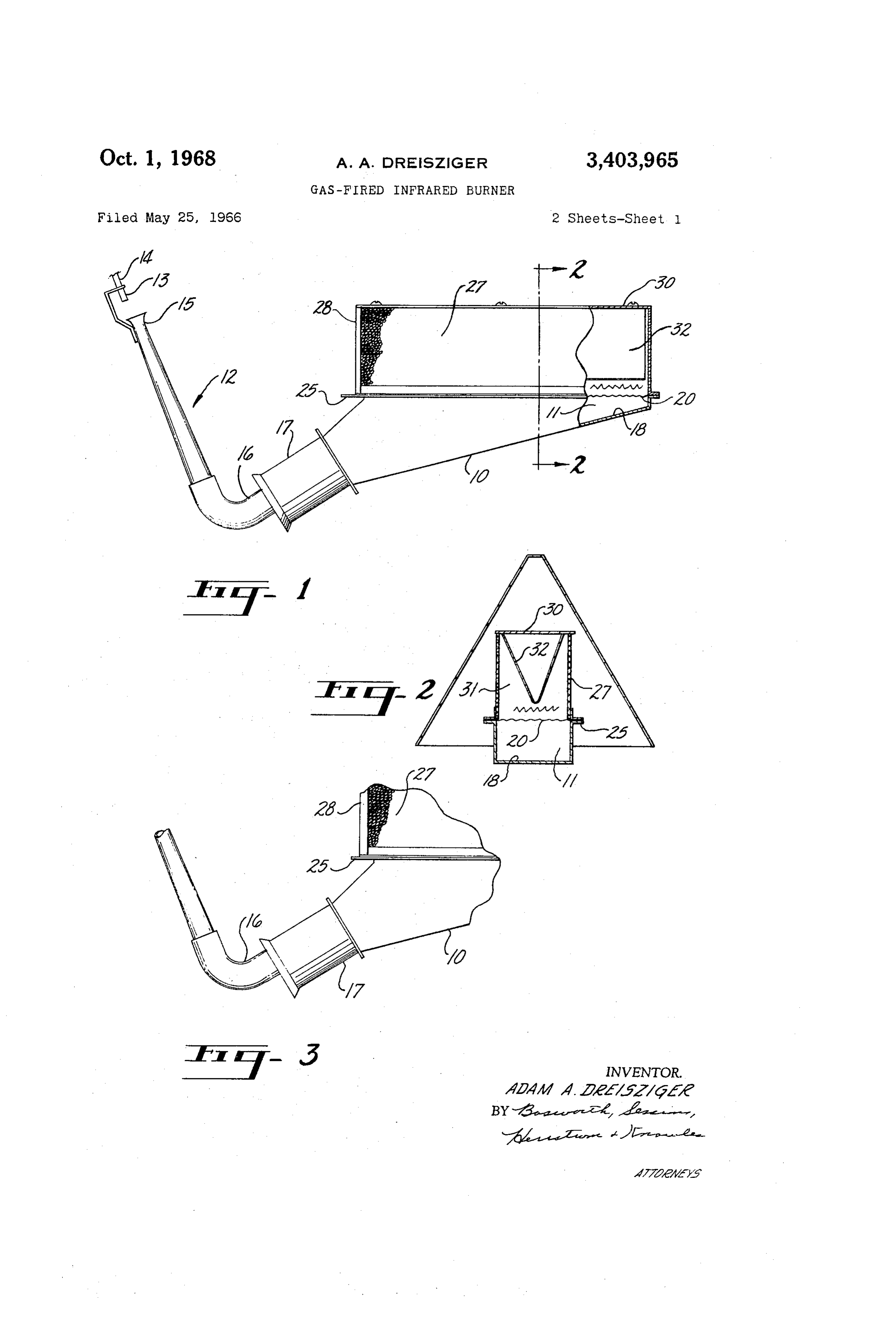
FIGURE 1 is an elevational view of an infrared space 50 stance theopen the total area amounts to about 29%. In this in mantle attains incandescence during operation heater embodying the invention with parts broken away and maintains a temperature of about 1500 F. and shown in section; Located above the mantle 27 is a divider assembly 30 FIGURE 2 is a transverse sectional view taken on the which defines with the mantle 27 and mantle retainer line 2-2 of FIGURE 1; assembly 26 an enclosed combustion chamber 31. Formed FIGURE 3 is a fragmentary side elevational view show 5 5 at the bottom of the divider assembly 30 is a V-shaped ing a modified form of the invention; and or wedge-shaped divider 32. The walls of the divider 32
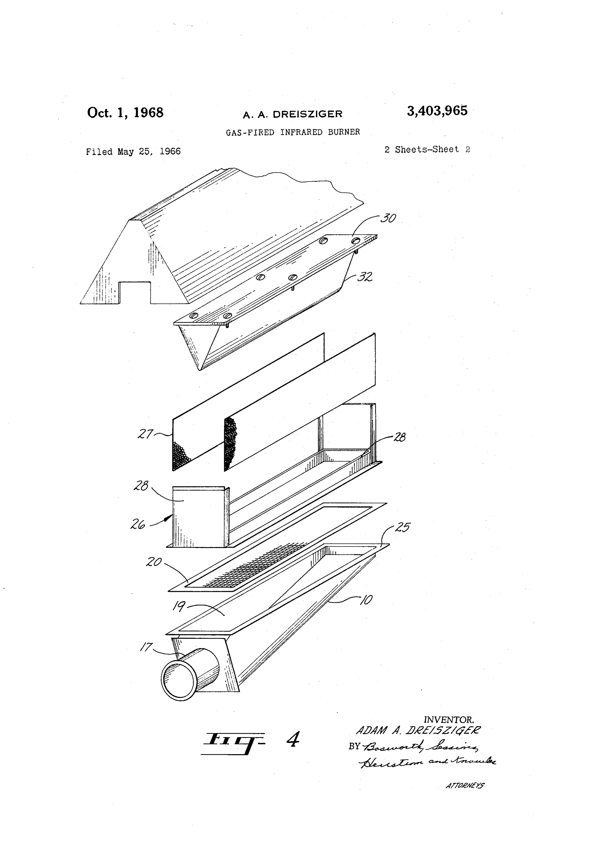
Figure
of FIGURE 1.
4 is an exploded perspective view of the heater are also formed of a high-temperature alloy which may Referring more particularly to the drawings, there is be the same as that used for the mantle 27. The sloping shown a gas fired infrared space heater embodying the 60 walls direct the gaseous combustion products laterally outward through the perforations in the mantle 27 so invention and utilizing a low pressure fuel gas as the that the heat energy carried by the gases is largely trans energy source.
The heater comprises a burner housing 10 which defines ferred to the mantle and assists in the heating of the a plenum 11 for a fuel-air mixture. mantle to incandescence.
The fuel-air mixture is introduced into the plenum in It will be noted that the apex of the wedge-shaped a combining ratio by means of a mixer tube assembly 12. divider 32 is spaced sufficiently above the flame layer so The mixer tube assembly includes a double venturi ar that there is no direct flame impingement thereon. rangement including an orifice fitting 13 communicating It will also be noted that the radiant mantle 27 and the with the fuel gas supply line 14. The orifice fitting 13 adjacent wall of the V-shaped divider 32 present in a di rection normal to mantle a solid incandescent front for directs a jet of fuel gas axially through a venturi throat () radiating 15 at the end of the mixer tube assembly 12 and thus heat in the form of infra-red energy. aspirates into the mixer tube assembly a volume of air OPERATION which mixes with the fuel gas. The resulting mixture is Under normal operating conditions the fuel gas to be directed through an orifice 16 at the opposite end of the burned in the combustion chamber 31 is directed from mixer tube assembly 12 to a second venturi throat 17 in the orifice fitting 13 to the first venturi throat 15 where
Page 5scan →
5 ergy released during combustion of said gaseous mixture it is mixed with air and channeled through a mixer tube whereby each side wall and said deflector provide a to a second orifice 16 where it is directed to a second ven solid incandescent front as viewed in a direction normal turi throat 17. At the second venturi throat 7 additional air is mixed in with the gaseous mixture to provide a re to said side wall.
sulting fuel-air mixture at approximately the combining 2. An infrared generator as defined in claim 1 wherein ratio. The mixture entering the plenum is deflected up said mixer. tube assembly includes means defining a first orifice communicating with a fuel gas supply line, means wardly by the floor of the burner housing in a uniform defining a first venturi throat, said first orifice adapted pattern through the burner screen. 20. At this stage suffi cient mixing of the fuel gas and air has been achieved to direct a fuel gas into said first venturi throat wherein air is drawn in and mixed with said fuel gas, means de to provide optimum combustion. After the gases pass 10 fining a second orifice communicating with said first ven through the burner screen 20 they are ignited and the re turi throat, means defining a second venturi throat com sulting combustion provides a flame layer in the combus municating with said plenum and having its axis parallel tion chamber 31 spaced above the burner Screen 20. to and spaced from the axis of said second orifice, said It will be noted that none of the flames impinge di second orifice being adapted to direct a gaseous fuel-air rectly upon any metallic parts of the heater A So that 5 mixture into said second venturi throat wherein addi the combustion is as complete as possible. The heat gen tional air is drawn in, mixed with said gaseous mixture erated in the combustion chamber serves to heat the walls of the perforated radiant mantle 27 and also the V and3.supplied to said plenum.
An infrared generator as defined in claim 1 wherein shaped divider 32 so that the elements become incan descent and radiate infra-red energy to the surrounding 20 said deflector is in the form of an elongated metallic member of V-shaped lateral cross-section, said member
Space.
The hot gaseous combustion products are directed by having its apex centrally located in said combustion cham ber approximately midway between said vertical side the V-shaped divider 32 through the perforations in the walls of said mantle.
radiant mantle 27 so that heat energy carried by the gases 4. In an infrared generator including means defining is partially transferred to the mantle. The escaped gases 25 a combustion chamber and means for burning a gaseous then mix with the air in the heated space, the concentra fuel-air mixture in said chamber, the improvement which tions of carbon monoxide and other undesirable gases being so small as to have no effect upon the comfort of comprises: a perforate mantle defining at least two oppo site side walls of said combustion chamber, said side persons occupying the enclosed heated space.
While the invention has been described with respect 30 walls being adapted to be heated to incandescence by the combustion of Said fuel-air mixture and being spaced to a specific embodiment thereof, it will be understood from said flame layer sufficiently to avoid any direct that this is for the purpose of illustration rather than flame impingement, and an imperforate wedge-shaped limitation and that other variations and modifications deflector projecting downwardly into said combustion will occur to those skilled in the art upon a reading of the chamber specification and drawings, all within the intended spirit .35 extendingalongitudinally major portion of the depth of said mantle and and scope of the invention as defined in the appended tially the length thereof,between said side walls substan said deflector adapted to be claims. heated to incandescence by the combustion of said fuel I claim: air mixture and to divert the gaseous products of combus 1. An infrared generator comprising a housing de 40 tion laterally outwardly through said perforations in said fining a plenum with an upwardly facing outlet, a mixer mantle, each of said opposite side walls and said de tube assembly for introducing a gaseous fuel-air mixture flector being adapted to project a solid incandescent front at substantially a combining ratio into said plenum, a as viewed in a direction normal to said side wall. burner screen located in horizontal relation over said plenum outlet and adapted to provide ports for the up References Cited ward passage of said gaseous mixture, the port loading of said screen being sufficient to maintain a flame layer UNITED STATES PATENTS spaced above said screen, means defining a combustion 669,302 3/1901 Franklin -------- 158-18X chamber above said burner screen, and including a perfo 1,074,312 9/1913 Collins ------------- 126-85 rate mantle having opposed side walls spaced from said 50 1,346,935 7/1920 Brigel ------------ 158-18 flame layer sufficiently to avoid any direct flame im 1,700,918 2/1929 Baker --------- 158-118 X pingement, an imperforate wedge-shaped deflector pro 2,386,978 10/1945 Ruhl -------------- 158-118 jecting downwardly into said combustion chamber a 2,985,137 5/1961 Horne -------- 126-92 X major portion of the depth of said mantle and extending 1,216,848 2/1917 Schmidt ------------ 126-86 longitudinally between said side walls substantially the 1,817,420 8/1931 Packer ------------ 126-92 length thereof, said deflector being adapted to divert the gaseous products of combustion laterally outwardly FREDERICK L. MATTESON, JR., Primary Examiner. through said perforations in said side walls and said de flector adapted to be heated to incandescence by the en H. B. RAMEY, Assistant Examiner.
Provenance
- Collection
- Patents citing this work
- Pages
- 5
- Method
- pdftotext (the PDF's own text layer) + pdftoppm 300dpi page scans
- Patent office record
- patents.google.com →
- Source
- Google Patents citing-documents table
- Assignee
- Bettcher Mfg Corp
- Published
- 1968-10-01
- Transcribed from
- patentimages.storage.googleapis.com →