

patent · US3413069A
Method and apparatus for eliminating furnace pulsations
26 November 1968
Text
Drawings
Page 1drawing sheetscan →
Page 2drawing sheetscan →
Page 3scan →
United States Patent Office 3,413,069 Patented Nov. 23, 1968
3,413,069 the disadvantage that the air taken into the combustion METHOD AND APPARATUS FOR ELMINATING chamber is not mixed with the air/oil mixture expelled FURNACE PULSATIONS from the burner. The inclusion of this ambient air direct Bruce R. Walsh, Wiikeasiurg, Pa., assignor to Grif Re ly into the combustion chamber has several detrimental Search & Development Company, Pittsburgh, Pa., a effects of combustion. These include a “chilling” effect corporation of Delaware on the flame, which results in poor combustion, resulting Filed Feb. 28, 1967, Ser. No. 619,215 in poor economy of use of fuel, increased smoke, and 10 Claims. (CI. 43-4) other harmful factors well known to those skilled in this art. Another disadvantage of this prior method of elimi nating pulsation is that the tube or opening constitutes a
ABSTRACT OF THE DISCLOSURE direct, open connection between the room and the com An air tube for gun type oil burners to eliminate pulsa bustion chamber. In the event of an abnormally high pres tion which includes means to mix both combustion gases Sure condition in the combustion chamber, such as is and room air into the main air stream upstream from 5 caused by Start-up or a downdraft in the smoke stack, a So-called "puff-back,' combustion gases, smoke, and soot the combustion chamber.
could be expelled into the room, causing health and
Hampresent safety hazards.
This invention pertains to oil burners of the so-called I have found that the inclusion of both a flow of com gun' type, which are widely used to burn fuel oil in bustion gases from the combustion chamber and a flow of ambient room air, into the stream of pressurized air flow domestic and commercial heating installations. These 20 ing burners include a self-contained air blower and means to through the blast tube to the combustion chamber re force the oil under pressure through an oil supply tube sults in the total elimination of or at least a very marked within the air tube. The blower, oil supply, and associated decrease in pulsations, and overcomes the above hazards. apparat LIS are usually in spaced relation to the combus The inclusion of combustion gases has the desirable tion chamber of the furnace in which the burner is being effect to preheating the air in the blast tube before it used, and the cylindrical air or blast tube interconnects mixes with the oil mist in the combustion chamber. The the combustion chamber of the furnace with the rest of inclusion of the ambient room air is thought to act as a the burner apparatus. The furnace may be associated with pressure leveler in that the combustion will always draw any type of heat distributing system, i.e., forced air, hot 30 in some room air through the apparatus of the invention, and depending upon the occurrence of abnormal pressure
Water, Or Steam.
A problem which sometimes arises in such heating in conditions in the combustion chamber may draw more stallations is pulsation. Pulsation is a vibrating of the or less than the normal amount of room air to alleviate flame, the combustion chamber, any loose parts, and even the abnormal pressure conditions to thereby prevent pulsa the entire furnace under extreme conditions, or any com tions.
bination of these elements, and can occur at start-up, dur The invention comprises a method and apparatus com ing running, and/or at stopping of combustion. Pulsation prising a blower or blast tube assembly which comprises is an undesirable phenomena in that it can extinguish the a pair of nested tubes with space between them at both flame, create noise, create noxious odors, wear the equip ends, the outer one of which is a cylindrical tube and the ment prematurely, cause smoke and soot to enter the 40 inner one of which comprises a pair of truncated cones furnace roon, and generally create unpleasant and un with their small ends face to face to form a venturi throat Safe situations. mediately the ends of the double tube assembly. A row of The reasons for the occurrence of pulsations generally openings are provided at the venturi throat in the inner are not fully understood, but certain things are strongly tube, and inlet ports are provided at both ends of the as Suspected causative agents. Certain combinations of the embly so that the passage of the pressurized air through physical configurations of the combustion chamber and 45 the inner tube and past the venturi throat will draw the burner resulting in poor air/oil mixing are thought to in both combustion gases from the front end of the blast be one cause of pulsation. Rough burning of the fuel oil tube assembly and room air from the rear end of the will cause pulsation, such rough burning being caused by blast tube assembly, and separately mix them into the interruptions in the smooth flow of air from the blower, flow of pressurized air from the blower at the venturi interruptions in the smooth flow of oil from the nozzle, throat.
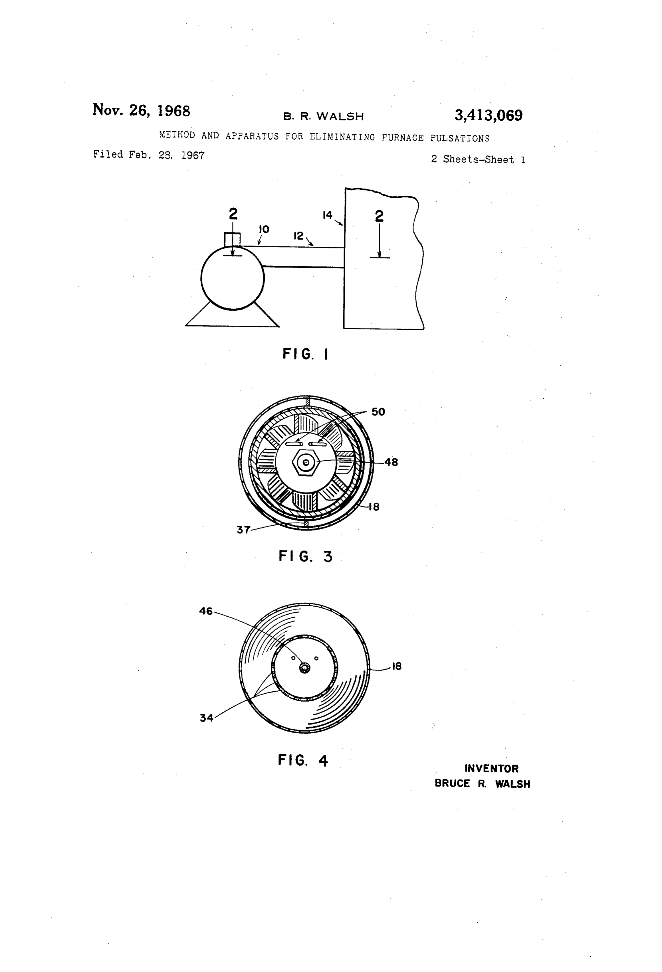
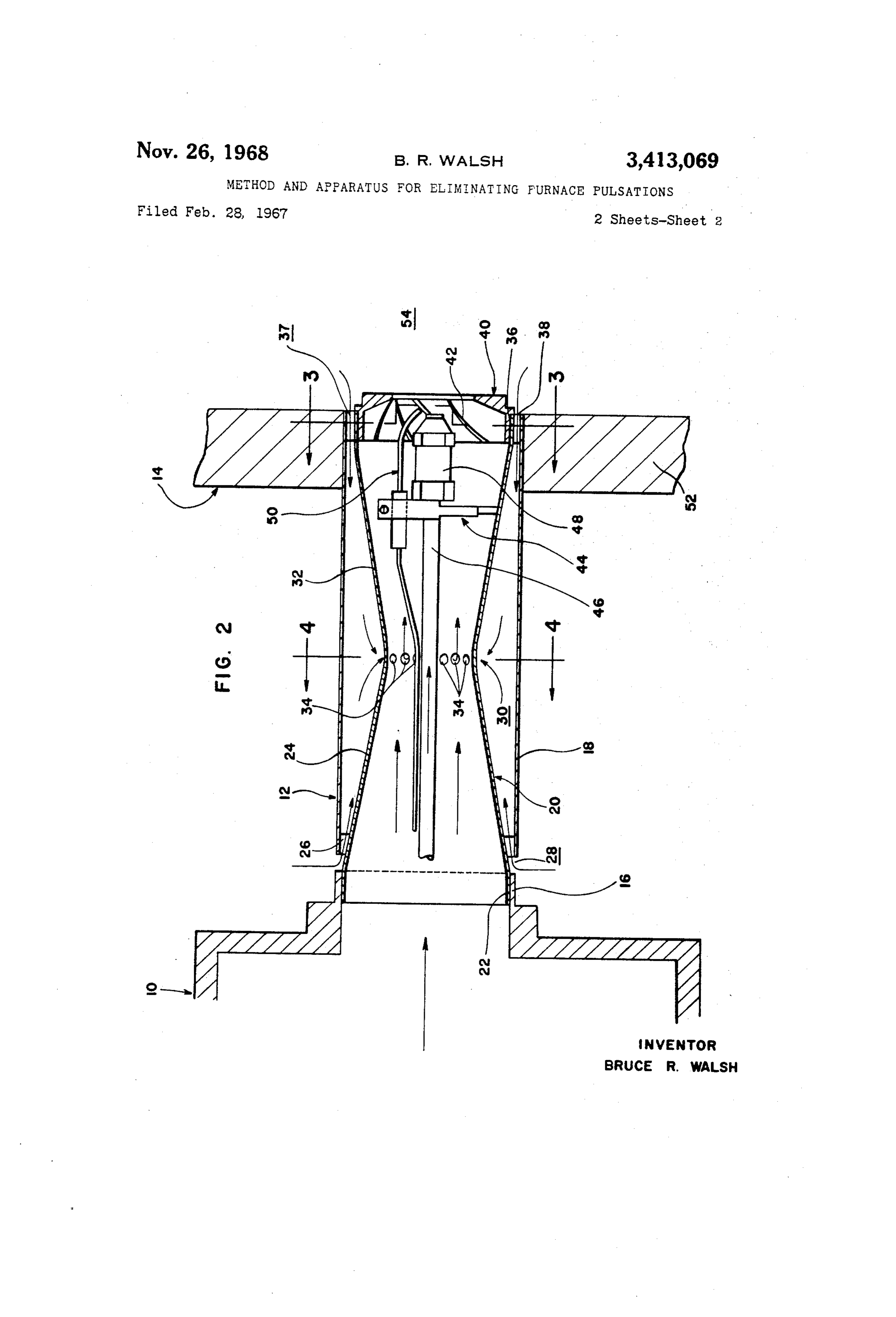
random recirculations, uneven drafts in the combustion Referring now to the accompanying drawing forming chamber, and abnormal pressure conditions in the blast a part of this disclosure: FIG. 1 is a partial side eleva tube and/or the combustion chamber. These abnormal tional view of a heating installation embodying the in pressure conditions can be caused by the above factors, 55 vention; FIG. 2 is a cross-sectional view taken on line 2-2 of FIG. 1 showing the blast tube assembly embody and it is thought that it is primarily abnormal pressure conditions which cause all pulsations, and that the other ing the invention; and FIGS. 3 and 4 are cross-sectional factors are not primary causes of pulsation, but only op views taken on lines 3-3 and 4-4 of FIG. 2 respec erate to cause pulsations because they operate to create tively.
abnormal pressure conditions. Referring now in detail to the drawing, 10 designates Starting pulsations are often caused by a slow start of 60 an oil burner which includes a blast tube assembly 12 the draft up the chimney. Running pulsations can be embodying the invention shown being used in a furnace caused by a poor draft or chimney, and is often rhythmic. 14. Blast tube assembly 12 is an integal one-piece struc Puisations during stopping could be caused by a low pres ture, and may be fabricated as a weldment, or in other Sure condition in the combustion chamber. The present suitable manner.
invention eliminates or at least very markedly reduces all As will be readily apparent to those skilled in this art, types of pulsation. the blast tube assembly 12 of the invention can be used One prior method of overcoming pulsation comprises in new installations, or can be easily substituted for the the provision of an opening, usually in the form of a short air tube in existing installations by merely removing the length of pipe, underneath the burner communicating the existing air tube, and Substituting assembly 12. In most combustion chamber with ambient room air. While this 70 cases, since the burners have standard size air outlet open method is effective in preventing pulsations, it suffers from ings, this Silbstitution can be accomplished by simply re 4 moving the adapting means at the burner and at the ing stopping of combustion, then the high suction in the furnace and reaffixing the same adapting means to the combustion chamber will draw room air into port 28 air tube of the invention. straight through annular chamber 30 and port 36 into the Burner 10, FIG. 2, comprises an outlet opening 16 combustion chamber to alleviate the abnormal condition through which air under pressure is passed by the blower, and prevent pulsation. If the opposite condition should not shown. Integral blast tube assembly 12 is formed occur, that is, an abnormally high pressure condition in from an outer cylindrical tube 18, and an inner member the combustion chamber 54, such as might be caused by 20. Member 20 comprises a rear cylindrical end portion start-up or running pulsations, then the combustion gases 22 that fits within outlet 6 of burner 10 and is Secured will not be able to flow out to atmosphere through annu therein by any suitable means, not shown. Forwardly of 0. there lar port 37, annular space 30 and annular port 28, because rear cylindrical end portion 22, member 20 is formed into is always some suction at the venturi throat. The a rear truncated cone portion 24. A set of rear Support combustion gases would be drawn into openings 34 and struts 26 connect the rear end of tube 18 with cone por recirculated. Thus, blast tube assembly 12 is provided tion 24 adjacent cylindrical portion 22. Thus, an annular with integral and automatic safety features to prevent inlet port 28 is provided between the rear end of tube 18 15 be combustion gases from entering the room should there and cone portion 24 to permit entry of room air into the some extraordinary happening within the combustion annular space 30 between tube 18 and inner member 20. chamber or stack such as "puff-back,' downdraft, or the The smaller end of a front truncated cone portion 32 is like.
joined to the smaller end of rear cone portion 24, and a The provision of end cone member 40 at the exit end venturi throat is formed at the plane of juncture. Inner 20 of impartingof the blast tube assembly 12 provides the advantage member 20 is formed with a row of openings 34 at the swirl to the flaming air-oil mist at substan venturi throat to admit gases therethrough from annular tially the plane of inlet ports 37. Further, end cone mem space 30 into the inside of inner member 20. The front ber 40 confines the fame and insures that the fame will large end of front cone portion 32 is formed into a be located spaced considerably inwardly of said inlet ports cylindrical portion 36 which is smaller than the diameter 25 of 37. Swirling the air at the exit and the confining feature of tube 18 and which is joined thereto by a plurality of the end cone, provides the advantage of insuring that front support struts 38 similar to rear struts 26. Thus, the back pressure or suction force always present behind an annular inlet port 37 is formed. between cylindrical the flame is spaced relatively far away from annular inlet portion 36 and tube 18 for admission of combustion gases ports 37. This insures that this suction force will not suck into annular space 30. 30 any gases out of said inlet ports, to further insure that Mounted on the inside of front cylindrical portion 36 the suction created at the row of openings 34 at the ven by any suitable means is a swirl end cone member 40, turi throat will suck combustion gases into annular space provided with swirl vanes 42, to cause the air and oil mix 30.
ture to Swirl to aid combustion, in the usual manner. The mixing of the room air and the combustion gases Spaced rearwardly of member 40 are support means 44 found separately into the main stream of pressurized air has been of any suitable type, which support an oil supply pipe 46 to entirely eliminate or at least very substantially which carriees an oil spray nozzle 48 of any type having reduce all pulsations.
its front end positioned substantially in the plane of end While the invention has been described in detail above, cone member 40. Support means 44 also carry electrical it is to be understood that this detailed description is by ignitors 50 to ignite the oil mist, or any other suitable 40 way of example only, and the protection granted is to be ignition means. The rear end of oil supply pipe 46 is at scope ofonly limited within the spirit of the invention and the the following claims.
tached to a suitable means to supply oil under pressure I claim:
in the burner 10, not shown. 1. A method of reducing pulsations in a heating instal The front end of blast tube assembly 12 is supported in lation which includes an oil burner having a blast tube; a fire wall 52 of furnace 4 by any suitable means not comprising the steps of substantially separately admixing shown, with the front ends of end cone member 40 and both ambient room air and combustion gases into the tube 12 positioned in the combustion chamber 54 of the main stream of pressurized air passing through said blast furnace 14.
Operation tube at said main stream upstream from the oil spray nozzle within said blast tube.
Air under pressure is supplied through outlet 16 of 2. The method of claim 1, constricting the flow stream the oil burner 10 and passes only through inner member of said pressurized air mediately the ends of said blast tube 20. Oil under pressure is supplied through supply pipe to create a region of reduced pressure at said constriction, 46 and nozzle 48 and is ignited by the igniting means 50. and causing said region of low pressure at said constric A region of low pressure will be created inside of member tion to draw in both said ambient room air and said com 20 at the vicinity of the openings 34 because of the action bustion gases into said main stream of pressurized air. of the venturi throat. As shown by the arrows on FIG. 2, 3. The method of claim 2, wherein said room air is air will be drawn through both annular ports 28 and 37 drawn in from the rear end of said blast tube to said con into annular space 30 and through the row of openings 34 stricted region and said combustion gases are drawn in to mix with the main stream of the pressurized air passing from the front end of said blast tube to said constricted through the inner member. 60 region.
As will be apparent from the symmetry of the structure 4. A blast tube assembly for a gun type oil burner com shown in FIG. 2, the suction at the row of openings 34 prising an inner member and an outer member, means to will draw gases into annular space 30 from annular port mount said inner member within said outer member, said 28 and annular port 37 with approximately equal force. mounting means comprising means to permit passage of Under normal conditions, the suction at the openings 65 fluids from the front and rear ends of said assembly be 34 will be considerably greater than the normal draft oc tween said inner and outer members to a space between curring in combustion chamber 54. A very slight draft on said members, said inner member being formed with a the order of .02 to .06 inch of water is present in the com constricted portion mediately the ends thereof, said con bustion chamber to permit the combustion gases to be stricted portion being formed with a plurality of openings, drawn up the stack or chimney. A conisderably larger 70 an oil spray nozzle, means to mount said nozzle within suction force, on the order of 5 or 6 inches of water, is said inner member adjacent one end thereof in position present at the row of openings 34 under normal opera to direct the spray from said nozzle outwardly of said tion. If, due to some extraordinary condition causing the blast tube assembly, whereby a flow of pressurized air suction in the combustion chamber to become greater through said inner member will create a Zone of reduced than the suction at openings 34, such as might occur dur pressure at Said constricted portion to draw gases through 5 said passage means at both the front and rear ends of said 8. A unitary, one-piece fluid handling article comprising tube assembly, through said space between said inner and an elongated inner member and an elongated outer mem outer members, and through said openings into the main ber, means to mount said inner member substantially co stream of the pressurized air passing through said inner extensively within said outer member, said inner member member. being formed with an inwardly constricted portion medi 5. The blast tube assembly of claim 4, said one end of ately the ends of said outer member, said constricted por said inner member terminating in a common traverse tion being formed with a row of openings communicating plane with the corresponding one end of said outer mem the space within said inner member with the space be ber, whereby said mounting means form an annular fluid tween said inner and outer members, said mounting means passage at said one end of said assembly; the other end 10 comprising front and rear sets of mounting struts in the of said inner member extending outwardly from said con space between and joining said inner and outer member stricted portion beyond the corresponding other end of together at the ends thereof to form front and rear ports said outer member, said mounting means connecting said at the front and rear ends of said article, whereby a flow other end of said outer member with a portion of said of fluid axially through said inner member will create inner member being spaced inwardly from the outer end a zone of reduced pressure at said constricted portion, thereof, said other end of said inner member being formed and whereby said Zone of reduced pressure will draw fluids into a cylindrical portion, said cylindrical portion being from outside the article into said space between said inner adapted to mount said inner member in fluid flow com and outer members from said front and rear ports and munication with the air outlet opening of an oil burner. through said openings into said flow of fluid through said 6. The blast tube assembly of claim 4, a swirl end cone inner member.
member, said end cone member comprising means to 20 9. The article of claim 8, and means at the rear end of swirl the flaming air oil mist issuing from said one end said inner member adapted to mount said inner member of said blast tube assembly, and means to mount said end in fluid flow communication with a Source of pressurized cone member within said inner member at said one end fluid.
thereof. 10. The article of claim 8, said outer member compris 7. The blast tube assembly of claim 4, said outer mem ing an elongated, straight length of plain cylindrical tub ber comprising a straight length of plain cylindrical tub ing, and said inner member comprising two truncated cone ing, said inner member comprising a pair of truncated portions having their Small ends joined together to form cone portions with their small ends joined to form said said inwardly constricted portion. constricted portion and with their outer ends adjacent 30 the ends of said outer member, said mounting means com References Cited prising front and rear sets of mounting struts in the space between and joining said inner and outer members to UNITED STATES PATENTS gether at the ends thereof, and the other end of said inner 1,629,253 5/1927 Breese --------------- 158 member extending outwardly beyond the corresponding 35 2,701,608 2/1955 Johnson -------------- 158-1 other end of said outer member, said outwardly extending 2,918, 117 12/1959 Griffin --------------- 158-1 end of said inner member comprising mounting means to mount said inner member of said blast tube assembly in FREDERICK L. MATTESON, JR., Primary Examiner. fluid flow communication with the air outlet opening of an oil burner, 40 E. G. FAVORS, Assistant Examiner.
Provenance
- Collection
- Patents citing this work
- Pages
- 5
- Method
- pdftotext (the PDF's own text layer) + pdftoppm 300dpi page scans
- Patent office record
- patents.google.com →
- Source
- Google Patents citing-documents table
- Assignee
- Gulf Research Development Co
- Published
- 1968-11-26
- Transcribed from
- patentimages.storage.googleapis.com →