

patent · US3471106A
Valveless microrocket systems
7 October 1969
Text
Drawings
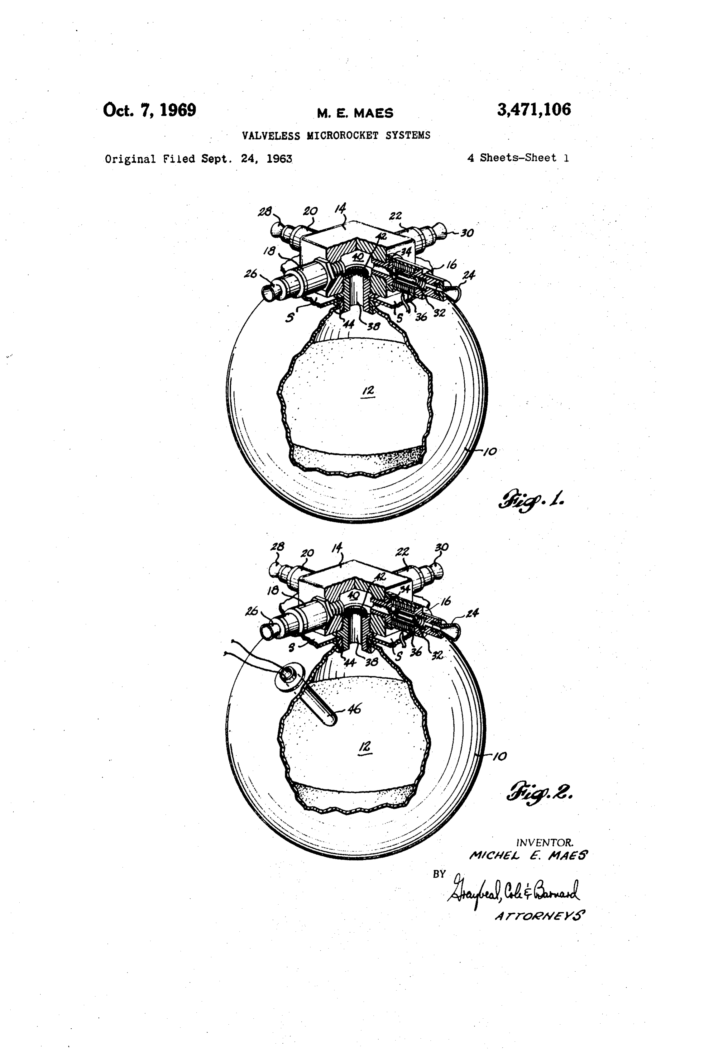
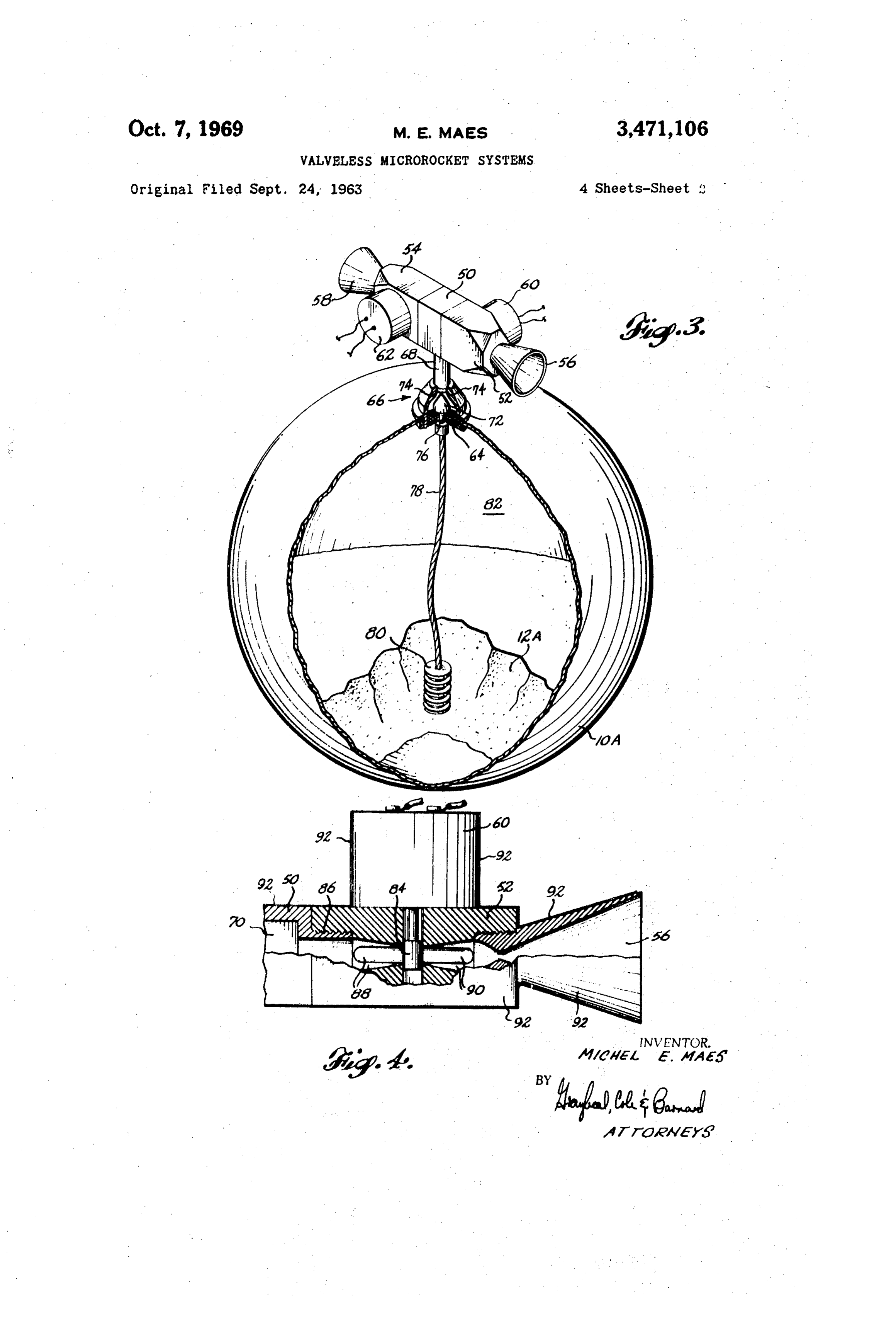
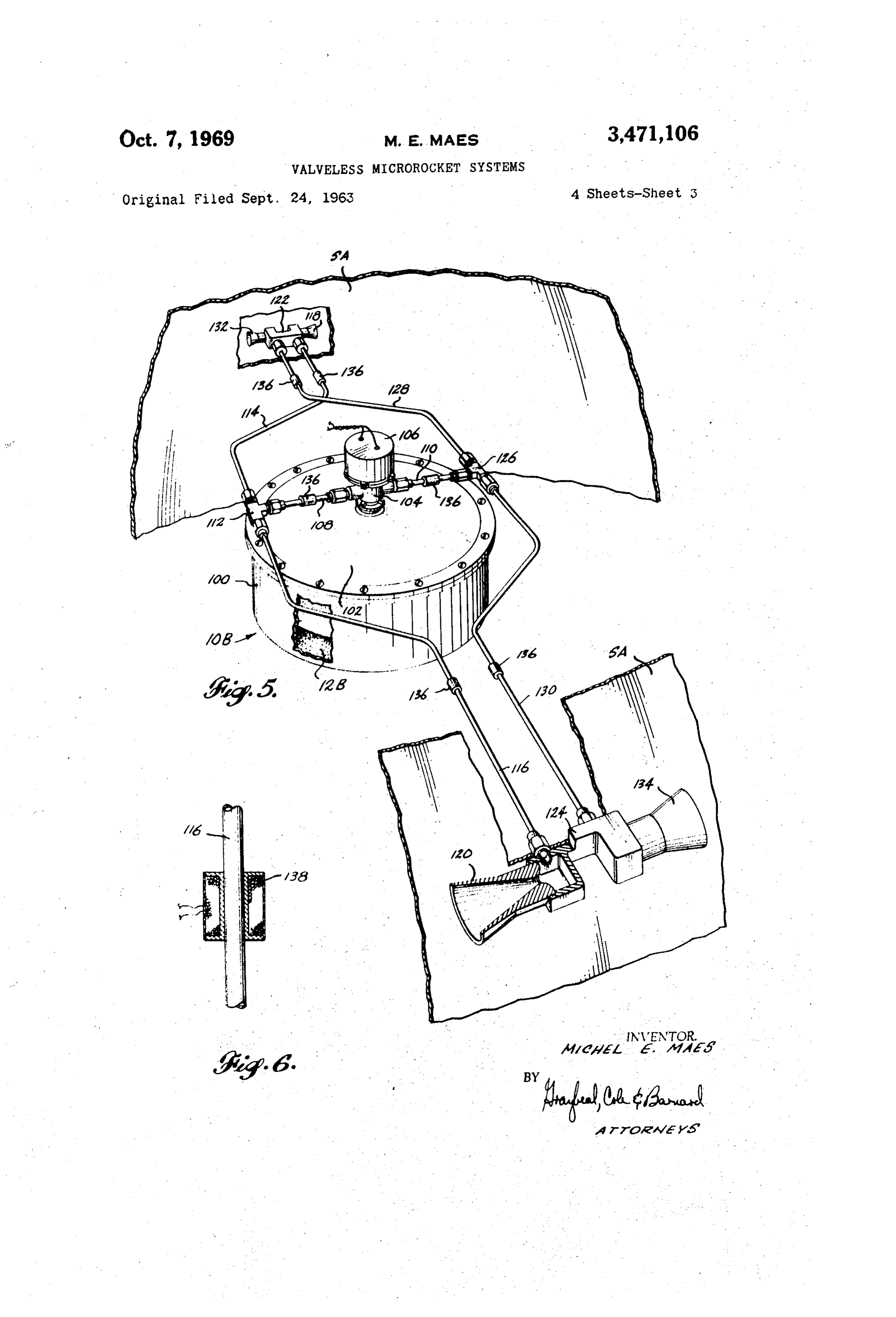
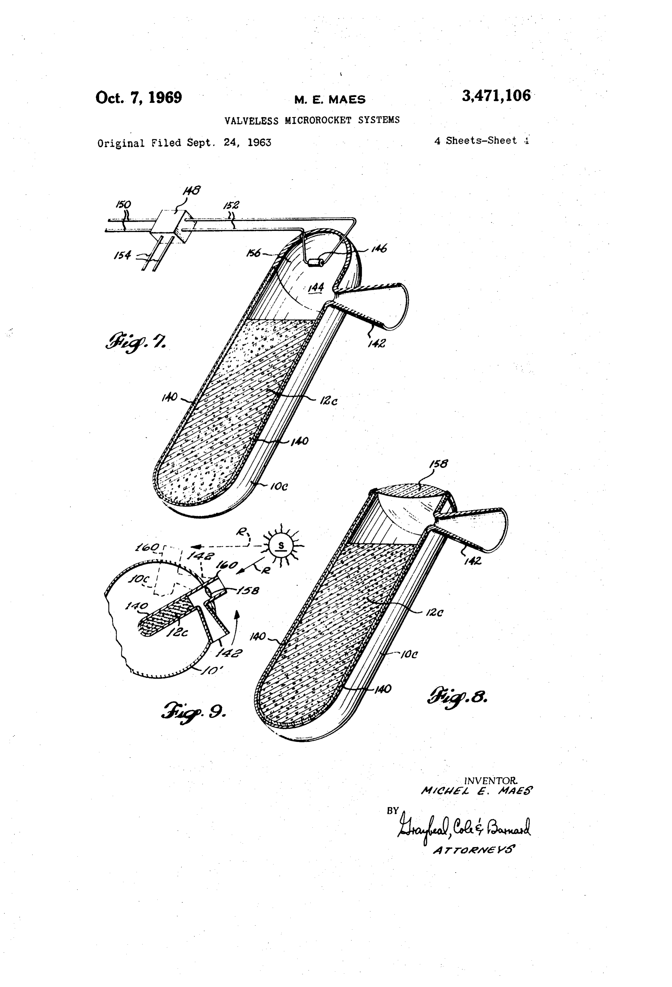
FIG. 3 is a further isometric cutaway view similar to FIGS. 1 and 2, showing a further modified form of sub liming solid microrocket, incorporating two oppositely directed nozzles and a thermally controlled variable ori fice functioning to maintain a substantially constant pro pellant mass flow during variation in propellant temper ature;
FIG. 6 is a fragmentary view of one of the propellant conduits of the rocket system shown in FIG. 5, illustrat ing a further modified form of flow path heating means therefor;
FIG. 7 is an isometric cutaway view of yet another form of sublimining solid microrocket characterizing the invention, with valveless control of propellant flow by means of selective radiant heating of the propellant sur face;
FIG. 8 is an isometric cutaway view of another form of valveless subliming solid microrocket wherein propel lant flow through the nozzle is controlled by heating of the propellant surface through the admission of solar energy, providing a completely passive control system; and
FIG. 9 is a fragmentary, cross-section view, in semi diagrammatic form, illustrating a manner of satellite at titude control utilized in the form of valveless subliming solid microrocket shown at FIG. 8.
Page 1drawing sheetscan →
Page 2drawing sheetscan →
Page 3drawing sheetscan →
Page 4drawing sheetscan →
Page 5scan →
Walveless microrocketsystems
Michel E. Maes, Beilevue, Wash., assignor to Rocket Research Corp., Seattle, Wash., a corporation of Washington
Original application Sept. 24, 1963, Ser. No. 311,054. Divided and this application May 28, 1965, Ser.
U.S. C. 244-1 15 Claims O
Abstract of the disclosure
The present invention relates to small, noncombustion type reaction jet systems, and more particularly to low thrust rocket systems utilizing a self-feeding, subliming Solid propellant to produce reaction propulsion. Specific aspects of the invention pertain to various of the factors involved as to selection of the subliming solid propellant, 20 as to design of system components and as to perform ance characteristics of rocket systems of this type. smusema
This application is a division of copending application Ser. No. 311,054, now abandoned, entitled Microrocket Systems Utilizing Subliming Solid Propellants, filed Sept.
Satellite mission studies and control system analyses have shown that only very little thrust is required to con 30 trol satellite attitude, orbital position, or spin rate. In general, attitude control for orbital space vehicles is best performed with a maximum of propellant economy through use of what may be termed microrockets, i.e. a rocket producing thrust on the order of about 10 to 10-6 pounds thrust.
Presently, the only type of operationally available pro pellant system for very low thrust applications utilizes cold nitrogen gas as the propellant. The major disadvan tages of the cold nitrogen gas system are that it requires a 40 relatively high system weight due to the low density of the propellant and requires a high pressure in the pro pellant storage tank (typically about 3,000 p.s.i.a. initial ly), coupled with the additional weight of the necessary pressure regulator mean and control valves. Character istically, a cold nitrogen gas reaction jet system requires that the weight of the propellant storage tank at least equal the initial weight of the propellant. Another major disadvantage of the cold gas system is the fact that the system contains a multiplicity of moving parts, operat ing under high pressure, often giving rise to considerable leakage and a low reliability with regard to satisfactory operation over extended periods.
It is a primary feature and advantage of the subliming solid microrocket system of the present invention that it offers better performance, higher reliability, and marked ly lower equipment weight than comparable cold nitro gen gas reaction jet systems, the subliming solid rocket system usually requiring a propellant tank weight which is only one-tenth or less of the initial weight of the pro 60 pellant. Further, the subliming solid microrocket is com pact, involves simple system components, is capable of providing higher specific impulse than a cold nitrogen gas system, has a greater propellant density, a generally much lower operating pressure (the exhaust pressure of the subliming solid system in most cases being 15 p.s.i.a. 65 or lower), is stable under storage, and has a longer op erating life capability. In addition, in contrast to com bustion type bi-propellant reaction jet systems, the sub limining solid microrockets of the present invention obvi 70 ates any need for either ignition or combustion. Further, the subliming solid microrocket of the present invention is self-feeding and is particularly suited to the intermit tent pulsing mode of operation characteristic of satellite attitude control.
These and other objects, features, advantages and char acteristics of microrockets with subliming solid propel lants will be apparent from the following discussion of various suitable subliming solid propellants, component designs, and system characteristics, taken together with the accompanying drawings illustrating certain typical and therefore non-limitive embodiments of the system, where in like letters and numerals refer to like parts, and wherein:
FIG. 1 is an isometric view, with various portions broken away to show interior detail, of a subliming solid control rocket involving four orthogonally related noz zles with control of propellant delivery to each of the nozzles being by separately actuatable valves; FIG. 2 is an isometric, cutaway view similar to the view of FIG. 1 showing a modified form of subliming solid microrocket system incorporating an auxiliary heat ing element within the propellant tank;
FIG. 3 is a further isometric cutaway view similar to FIGS. 1 and 2, showing a further modified form of sub liming solid microrocket, incorporating two oppositely directed nozzles and a thermally controlled variable ori fice functioning to maintain a substantially constant pro pellant mass flow during variation in propellant temper ature;
FIG. 4 is an enlarged detail view partially in cross section and partially in elevation, showing further sole noid valve and nozzle detail of the nozzle assembly in corporated in the subliming solid microrocket shown in FIG. 3, and further illustrating a suitable technique for maintaining the valve and nozzle at somewhat higher tem perature than the propellant to inhibit propellant recon densation;
FIG. 5 is an isometric view, with portions broken away to show interior detail, of a further modified form of subliming solid microrocket system according to the pres ent invention, specially adapted for spin control of a satellite, with oppositely related nozzles fed from a com mon bidirectional control valve, the system shown in FIG. 5 also incorporating a modified form of flow path heating means;
FIG. 6 is a fragmentary view of one of the propellant conduits of the rocket system shown in FIG. 5, illustrat ing a further modified form of flow path heating means therefor;
FIG. 7 is an isometric cutaway view of yet another form of sublimining solid microrocket characterizing the invention, with valveless control of propellant flow by means of selective radiant heating of the propellant sur face;
FIG. 8 is an isometric cutaway view of another form of valveless subliming solid microrocket wherein propel lant flow through the nozzle is controlled by heating of the propellant surface through the admission of solar energy, providing a completely passive control system; and
FIG. 9 is a fragmentary, cross-section view, in semi diagrammatic form, illustrating a manner of satellite at titude control utilized in the form of valveless subliming solid microrocket shown at FIG. 8.
The form of subliming solid microrocket shown in FIG. 1 comprises a propellant tank 10 of spherical con figuration and constructed of a suitable lightweight ma terial such as aluminum or glass fiber reinforced resin, for example. The subliming solid propellant, in the micro rocket shown at FIG. 1, is a compressed powder cake 12 which, as will be readily understood, initially occupies substantially all of the tank 10 and gradually reduces in size by surface sublimation, the propellant cake 12 shown in FIG. 1 being in a partially depleted state. Mounted at 6 the top of the propellant tank 10 is a thrustor block 14 propellant 12A. The temperature sensing expansion ele in which are threadedly mounted four valve and nozzle ment 80 and the thermally controlled variable orifice as assemblies comprising respective solenoid valves 16, 18, sembly 66 constitute a commercially available unit, con 20, 22, each in communication with respective nozzles 24, ventional per se, and the operation thereof is such that 26, 28, 30. Each of the valves 16, 18, 20, is a solenoid with an increase in temperature at the sensing element actuated coaxial type valve, conventional per se, com 80, element 80 moves push rod 76 which in turn moves prising (as shown in the cutaway view of valve 16) a pintle 72 to relatively reduce the orifice area between spring-loaded plunger 32 actuated away from the valve the pintle 72 and the contoured wall 74, with the result seat 34 by energization of solenoid coil 36. Each of the that on the occasion of propellant flow the flow rate of nozzles 24, 26, 28, 30 is perse of the conventional conical 10 propellant vapor through the orifice and into the thrustor type. As will be apparent in FIG. 1, the flow of propellant block 50 is maintained substantially constant in spite of vapor from the tank 10 into the thrustor block 14 is the change in vapor pressure of the propellant caused by through threaded fitting 38 into the interior chamber 40 change in temperature.
of the thrustor block 14, thence out whichever valve and As an operational refinement of microrockets accord nozzle assembly is open. In order to prevent any solid 5 ing to the invention, such as that shown at FIG. 3, particle movement from the propellant tank 10 into the nitrogen gas can be initially placed in the space 82 in valve and nozzle assemblies, a filter screen 42 is seated tank 10A not occupied by solid propellant 12A, at in the fitting 38. Fitting 38 on which the thrustor block moderate pressure (about 150 p.s.i.a., for example), in 14 is mounted is in turn attached to the tank 10 by order to extend the initial pulse duration of the system threaded engagement with outlet port 44 welded to the 20 without regard to providing heat of sublimation, such tank 10, and a convenient manner of mounting the micro as often required during initial acquisition of desired rocket to the satellite which it controls is to clamp the satellite attitude immediately after reaching orbital veloc skin or casing of the satellite between the tank outlet ity. In this manner, a single attitude control system can port 44 and the fitting 38, a fragment of the satellite cas be made to optimally perform both the functions of ing being shown so assembled, at S. 25 initial attitude acquisition and of long term attitude con In order to be compatible with the propellant vapor, trol.
the various flow path means for the vapor are constructed FIG. 4 presents an enlarged detail view of a portion of a material not subject to chemical attack by the vapor, of the thrustor block 50 and the valve 52, nozzle 56 Such as aluminum or stainless steel. assembly shown in FIG. 3. As shown, the valve 52 is FIG. 2 illustrates a modified form of the subliming 30 of the shear seal type, opened upon energization of solid control rocket shown in FIG. 1, incorporating all Solenoid 60, movement of the shear seal block 84 up of the components discussed above and further including wardly (as viewed) permitting propellant vapor flow from a selectively energized electric heating element 46 thread chamber 70 of the thrustor block 50 through thrustor edly mounted in the propellant tank 10 and extending into block passage 86 and valve passages 88, 90 into the the tank 10 So as to radiantly heat the propellant cake 12 35 reaction nozzle 56, in the event operating conditions are such that auxiliary One of the operational considerations with respect heating of the propellant is desirable or required to main to a subliming solid propellant system is that all flow tain operating vapor pressure. One of the operating char paths for the propellant vapor are in many cases to acteristics of a subliming solid microrocket is that heat be maintained at a temperature which inhibits recon is required to cause the propellant to sublime, i.e. the densation of the propellant vapor. One simple way to propellant has a certain heat of sublimation requirement. do this is to maintain the flow paths at a slightly higher In general, the necessary heat of sublimation is attained temperature than the recondensation temperature of the by the propellant through the propellant tank by thermal propellant vapor, and as illustrated in FIG. 4 with re conduction and radiation from the surroundings. How spect to the block 50, valve 52 and nozzle 56, for exam ever, in those cases where adequate heat cannot be drawn ple, is to provide the flow path exterior surfaces, or at from the surroundings to maintain the propellant at de least portions thereof, with a surface coating having a sired operating temperature, the auxiliary heating element coefficient of thermal absorptivity causing preferential 46 prevents the temperature of the propellant cake 12 heating of the flow path elements. For this purpose, the from falling below the desired operating level. Heating valve and nozzle assembly shown in FIG. 4 includes a element 46 thus serves to in effect extend the maximum thermally absorptive coating, typically a flat black paint, time during tinuously.
which the microrocket can be operated con 50 as indicated at 92.
Another way in which the propellant vapor flow path
FIG. 3 illustrates further typical variations in sublim means can be conveniently heated, particularly under ing solid microrocket component arrangements. In the conditions where the flow path means are exposed to a form of rocket shown in FIG. 3, the generally spherical low temperature environment compared to the tempera propellant tank 10A is partially filled with subliming solid 55 ture within the propellant tank, is to provide the neces propellant 12A, in this case in loose powder form, and sary heat by means of a small continuous current pass the control valve nozzle assemblage comprises thrustor ing through the solenoid coils of the flow path valve block 50 and respective oppositely related valves 52, 54 means at a level below that required for solenoid actu and nozzles 56, 58. The said valves 52, 54 are of the shear ation. A power input on the order of a few tenths of Seal type, conventional per se, selectively controlled by 60 a Watt, applied in this manner, is sufficient to maintain respective solenoids 60, 62, the specific construction there the valve and associated components at appropriate tem of being shown in more detail in FIG. 4 and discussed perature even when the flow path components are ex below. Nozzles 56, 58 are of a conical type, conventional posed to the black background of deep space. Thus, a per se. Flow of propellant vapor from the tank 10A to the Small heating current through the coils of solenoids 60, thrustor block 50 is through a filter screen 64 and through 65 62 in the system illustrated at FIG. 3, or through the a thermally controlled variable orifice assembly 66, Solenoids of valves 16, 18, 20, 22 in the systems illus then through mounting tube 68 into the manifold cham trated at FIGS. 1 and 2 can also serve to provide the ber 70 (see FIG. 4) of the thrustor block 50. The ther flow path temperature condition desired to inhibit pro mally controlled variable orifice assembly 66 is threadedly pellant recondensation. As will be apparent, this tech mounted to the top of tank 10A and the functional por 70 nique can be applied in conjunction with other forms of tions of this assembly comprise a pintle 72 facing the flow path heating means, such as the temperature ab contoured internal wall 74 of the orifice chamber sur Sorptive coating illustrated in FIG. 4, for example. rounding the pintle 72. Said pintle 72 is linked by a flexi FIG. 5 is an isometric view, with certain portions ble push rod 76 in flexible sheath 78 leading to a tem broken away to show interior detail, of another typical perature Sensing expansion element 80 within the solid 75 component arrangement for subliming solid microrocket 7 system characteristic of the invention, specifically con in direct and open communication with the chamber 144 figured to provide pure-couple spin control. In this sys above the propellant cake 12C. Selective heating of the tem, the propellant tank, generally indicated at 10B, com exposed surface of propellant cake 12C is by means of prises cylinder 100 with a closed bottom and a dished electric heating element 146, suitably energized on com cover 102 bolted in place thereon to provide a pressure mand, as by means of solid state power switch 148, of a enclosure for a packed powder cake 12B of subliming type conventional per se, applying a power input from solid propellant. Exhaust or propellant vapor from the conductors 150 to the heating element 146 through con propellant tank 10B is controlled by means of a three ductors 152 at such time as the normally open power position shear seal valve 104 controlled bidirectionally by switch 148 receives energization from a control input an electrically energized torque motor 106. The said valve O applied to conductors 154. A generally hemispherical 104 having three control positions, delivering propellant reflector 156 is preferably employed, to direct the radiant vapor to either outlet conduit 108 or outlet conduit energy from heating element 146 onto the surface of the 110 depending upon the polarity of energization of the propellant cake 12C. In a case where the propellant cake torque motor 106, with a center control position pre 12C is relatively light in color, a small amount of finely venting propellant flow to either outlet conduit when no divided particles which are darker in color, such as car energization of the torque motor 106 is provided. The bon black, can be dispersed in the propellant cake 12C in three-way valve 104 and torque motor 106 shown in order to improve the heat absorption characteristics of FIG. 5 is a commercially available unit, conventional the propellant cake surface.
per se, and accordingly need not be further described The mode of operation of a valveless form of sub for an understanding of the operation thereof. 20 liming solid microrocket such as shown at FIG. 7 is as The flow path arrangement for propellant vapor de follows. Assuming that the propellant cake 12C is at an livered to conduit 108 comprises a T-fitting 112 and initially ambient temperature, an initial vaporization of conduits 114, 116, respectively in communication with propellant occurs until by the loss of heat of sublimation oppositely directed conical nozzles 118, 120 through the the thermally insulated propellant cake is refrigerated to passageways provided in respective thrustor blocks 122, 25 the point where the vapor pressure of the propellant is 124, each identical with the other, the nozzle 120 and so low that substantially no propellant flow exists. This its associated passageway in thrustor block 124 being cut condition continues to exist as long as there is no heat away in FIG. 5 to show some of the interior detail input to the propellant cake. Since there is substantially thereof. Similarly, propellant vapor delivered to conduit no propellant flow and no thrust is being produced, this 110 flows through T-fitting 126 and respective conduits 30 condition can be referred to as a nonoperative or “off” 128, 130 to the thrustor blocks 122, 124 and nozzles condition. At such time as an operating “pulse' is desired, 132, 134. the heating element 46 is energized and the heat input Mounting of the microrocket system shown in FIG. to the surface of the self-refrigerated propellant cake 12C 5 in the satellite which it controls can be by suitable causes localized heating of the surface thereof, producing attachment of the thrustor blocks 122, 124 externally 35 propellant vapor by surface Sublimation and vapor flow of the satellite casing, indicated fragmentarily at SA, out of the open nozzle 142. This thrust producing flow of the microrocket system components internally of the propellant vapor out the nozzle 142 can be referred to as satellite being supported by suitable structure means, not the operating or “on” condition, which condition will shown. continue substantially only as long as the heating element The microrocket system shown in FIG. 5 is further 146 remains energized. Thus, the valveless microrocket characterized by utilization of a different form of pro shown in FiG. 7 can be "pulsed' for any desired period pellant vapor flow path heating means than that shown simply by selective energization of the heating element in FIG. 4. Specifically, by way of further example, with 146. A primary feature and advantage of the valveless respect to such flow path heating means, the various microrocket according to the present invention is that conduits 108, 110, 114, 116, 128, 130 are each pro pulses of thrust are produced on command without the vided with a sleeve 136 or the like containing radioactive 45 use of moving parts to control propellant flow. The ab material such as Pm 147 or Pu238. Fission of the radio sence of any moving parts in the system has the capability active material provides a degree of thermal heating of of providing extremely high unit reliability. It will be the various conduits and associated components in therm apparent that, in a valveless microrocket such as shown ally conductive association therewith. As will be ap at FIG. 7, any type of means for selectively producing parent, the radioactive material to accomplish this pur 50 energy other than electric heating element 146 can be used pose can be present in various forms other than the sleeves to selectively generate propellant flow. By way of further 136 shown, such as by being applied as internal or ex examples, the selectively controllable radiant energy pro ternal films or coatings in or on the conduits or por ducing means can be: (a) a chemical reaction type heat tions thereof, or as by being placed within suitable com Source, such as a small oxy-hydrocarbon burner, pref partmentation in the valve 104 and/or the thrustor blocks 55 erably with the heat produced products of combustion 122, 124, simply by way of further example. being separately exhausted without introduction to the FIG. 6 is a fragmentary isometric view showing a propellant tank; (b) a dielectric heating means, such as further form of flow path heater means which can be used spaced dielectric plates arranged within the solid pro in lieu of the radioactive sleeves 136. In this heating ar pellant or at spaced points on the insulative wall 140; rangement an electric sleeve heater, Suitably energized, 60 (c) electroconductive heating means, such as electrodes thermally heats each conduit, such as shown in FIG. 6 immersed in and passing electrical current directly through at 138 with respect to conduit 116. the solid propellant mass; or (d) a laser type device, FIG. 7 typically illustrates what may be termed a such as a silicon carbide crystal laser controlled by the subliming solid microrocket of the valveless type. In this quantity of electrical current flow through the crystal. form of rocket system characteristic of the invention, the 65 Yet another technique for selectively heating the sur control of propellant vapor flow is solely by means of face of a valveless subliming solid microrocket to pro selective heating of the propellant. More specifically, in duce thrust on demand is to heat the surface with solar the rocket shown in FIG. 7, a generally cylindrical, round energy. An example of a valveless microrocket embodying ended propellant tank 10C is partially filled with a com this principle is presented at FIG. 8, and a somewhat dia pacted cake 12C of subliming solid propellant, with an grammatic illustration of a manner of use of such micro insulating sheath 140 being provided between the tank rocket is illustrated at FIG. 9. In FIGS. 8 and 9, the tank and propellant to prevent heat transfer to the propellant 10C, propellant cake A2C, insulative liner 140 and nozzle cake 12C through the wall of tank 10C. A conical reaction arrangement 42 are arranged in the same manner as in nozzle 142 is attached to the tank 10C at a point thereof the valveless rocket illustrated at FIG. 7, and correspond above the propellant cake 12c the said nozzle 142 being 75 8 ingly so designated. To provide selective heating of the be at least about 0.5 p.s.i.a. and preferably not over about exposed surface of propellant cake 12C, the end of tank 15 p.s.i.a. except when the desired thrust level requires a 10C facing the propellant surface is provided with a light higher vapor pressure (such as the 330 p.s.i.a. vapor pres transmitting window such as quartz lens 158. FIG. 9 Sure for a thrust level of 10 pounds, using PHCl as the shows an application of this type of microrocket for propellant, for example).
Satellite attitude control as shown by broken lines in FIG. With respect to the temperature or the subliming solid 9, microrocket can be oriented on the satellite 10' in propellant at which substantial propellant vapor flow Such a manner that, when correct satellite attitude is ob through the reaction nozzle occurs, such temperature can tained, no incident sunlight rays R from solar sources S not be too low, otherwise the propellant will sublime strike the quartz lens 158 and no thrust is produced by 10 under unexpected environmental conditions resulting in the microrocket. However, should the satellite 10' move higher than design temperatures. The propellant should out of correct attitude, the quartz lens 158 receives in be specifically selected for each application to insure cident sunlight rays R from solar source S and the solar compatibility between the propellant sublimation tempera energy transmitted through the quartz lens 58 onto the ture and the expected satellite environmental conditions. Surface of the propellant cake 12C causes surface sub 5 In general, the sublimation temperature should be sub limation of the propellant and the microrocket produces stantially above 65 F. and preferably should be at least thrust by propellant flow through nozzle 142, returning above about 120 F.
the Satellite to correct attitude, at which time the sun With respect to molecular weight of the propellant light rays R no longer strike the propellant and the thrust vapor, it is necessary to have a reasonably good specific is interrupted. It is to be noted that in this form of valve 20 impulse (Is), i.e. at least about 40 and preferably at less microrocket, the control of thrust generation is en least about 75 lbf./Ibm./sec., in order to obtain good per tirely passive, i.e. requires no control energy producing formance from a subliming solid propellant system. As means and no active control elements on board the is known, the primary physical quantity which effects satellite. the specific impulse (pounds of thrust produced per unit As will be evident, a suitable shield and optical sys 25 weight flow of propellant per second) is the molecular tem can be used in conjunction with the light transmit weight of the exhaust gases. It is desirable to have ting quartz lens 158 to bring incident solar energy onto the molecular weight of the exhaust gases as low as pos the solid propellant only when attitude correction is de sible. In this respect it is to be emphasized that most sired. For example, angle of incidence of solar energ substances which have an appropriate vapor pressure are operable to produce attitude corrective thrust can be nar 30 impractical because of the fact that the molecular weight rowed and can have sharp angular demarkation, as by of the substance in vapor phase is undesirably high; this use of a light shielding tube around the lens 158, with a is often particularly true in the case of volatile organic slotted or like aperture (not shown) at the tube end materials such as naphthalene. It is thus an important opposite from the lens if desired. characteristic of most subliming solid propellants suit While the term “valveless' has been used to decribe 35 able for purposes of the present invention, as listed in the type of subliming solid rocket such as shown at the table below, that they reversibly decompose upon FIGS. 7 and 8 where thrust generation is controlled solely sublimation from the solid phase to form a gas phase by control of the energy input to the subliming solid mixture of lighter compounds. Thus, for example, am propellant, it will be understood that use of a simple 40 monium hydrosulfide reversibly becomes ammonia and spring-loaded over pressure relief valve or the like in the hydrogen sulfide in gas phase, and ammonium bicarbo propellant vapor flow path between the chamber 144 and nate reversibly becomes ammonia, water vapor, and CO the reaction nozzle 142, to permit exhaust of propellant in gas phase, with these respective gas phases having vapor only when the vapor pressure is above a certain molecular weights of 25.6 and 26.4, for example. In gen level (e.g. 0.5 p.s.i.a.), is not inconsistent with the essen eral the molecular weight of the subliming propellant tial "valveless' mode of propulsion control character vapor should be not more than about 108, preferably istic of this type of rocket and is to be considered within should be less than about 60, and optimally should be the scope of the present invention. less than about 30.
Having considered the component makeup of various As to the density of the subliming solid propellant, subliming solid reaction jet systems characteristic of the it is desirable that it be as dense as possible in order to invention, consideration will next be given to the matter reduce the weight of the propellant tank for a given of subliming solid propellant selection, including an in amount of propellant. In general, the density of the sub dication of the basic properties of suitable propellants liming solid propellant should be at least about 0.05 and the chemical constituency thereof. pounds mass per cubic inch.
As to the criteria for propellant selection, the important :5 5 The heat of vaporization of the propellant should be properties to be considered are vapor pressure, melting as low as possible, since this directly determines the al point, molecular weight of the propellant vapor, density, Iowable pulse length and maximum duty cycle as a func heat of sublimation, specific impulse, and chemical sta tion of the thrust level and amount of propellant in the bility. With regard to vapor pressure, the subliming solid tank. As will be eivedent, if the heat of vaporization is propellant must possess a significant vapor pressure at 60 excessively large, then the self-cooling effect during the operating temperature and the operating vapor pressure pulse becomes more pronounced. In general, the heat should fall within certain limits to obtain optimum per of vaporization of the subliming solid propellant should formance, which limits depend to a considerable extent not exceed about 1000 B.t.u./Ib. upon the thrust level under consideration. For example, It is also important that the propellant material ex if the vapor pressure of a propellant is too high, rela hibit chemical stability under operating and storage con tive to the thrust level, the throat area of the exhaust ditions and should not have corrosive, toxic, or other un nozzle is unduly small and might tend to be obstructed desirable characteristics unless such can be tolerated in should operating conditions vary considerably from those the environment of use.
for which the system was designed. If the vapor pressure 70 The following is a tabulation of certain suitable sub is too low, on the other hand, the nozzle throat area liming solid propellants for use in microrocket systems becomes excessively large, leading to undue weight of according to the present invention, such as those shown in the nozzles, flow path conduits and valves. By way of the accompanying illustrations, together with an indication practical limits with respect to nozzle throat diameters of the various above-discussed physical and chemical prop and vapor pressures, the propellant vapor pressure should 75 erties of the propellants.
Page 9scan →
Table-properties of subliming solid propellants
Vapor Molecular Approx. r . . .. .
pressure Sublimation weight Heat of theo. a Chemical at 65° F. point of gas Density sublimation specific if stability
Subliming solid propellant Formula (lbf.fin.) (o F.) phase (lbm.fin.3) (B.t.uflib.) impuise (I) (at 65° F.) Ammonium bicarbonate---------- NHHCO 0, 62. Above 150 26, 4 0.0572 929 84 Stable. Ammonium carbonate--- -- (NH4)2COs 0.6 Above 150 24.0 Above 0.05 960 86 Do. Ammonium carbamate.-- NH4CONH 1.16 Above 150 26.0 Above 0.05 877 84 Do. Ammonium hydrosulfide NHHS 6.37 Above 150 25.6 0.05 782 85 Do. Ammonium sulfide------ (NH4)2S 7.0 Above 150 22.8 Above 0.05 -...----------- 87 Do. Ammonium cyanide----- - NEICN 7.55 97 22.0 Above 0.05 825 87 Do. Cyanogen bromide---------------- CNBr. 1.55 124 105.9 0.073 120 42 Do. Phosphonium chloride--- -- PHC 330 82 35.2 Above 0.05 -------------- 72 Do, Phosphonium bromide- -- PBT 4.2 Above 150 57.4. Above 0.05 -------------- 57 Do. Phosphoninim iodide-- PHI i. 1 143 81.0 0.103 -------------- 47 Do. Sulfur trioxide.-------- SO3 0.87 44 80.0 0.07 366 48 DO. Nitrogen pentaoxide-------------- NOs 4.8 86 108.0 0.059 -------------- 41 Do.
Since sublimation of each of the propellants listed stood that any other form of suitable energy source can in the table is essentially a physical phenomenon, it will be employed, such as the energy producing means above be understood that any chemically non-reactive mixtures discussed in connection with the form of rocket shown of subliming solid propellants can also be employed if at FIG. 7. Yet another specific example in this respect, desired. applicable where a continuous (i.e. non-controlled) heat The following specific examples typify some of the de 20 ing of the subliming solid propellant is desired to main sign considerations involved in designing subliming solid tain a relatively high level propellant vapor pressure, is microrockets for particular applications at various thrust the utilization of a radioactive material containing loose levels. For a subliming solid microrocket to operate at apellet or the like placed in the propellant tank along with thrust level of 10-6 lb. at a temperature of 65. F., one a propellant. - good subliming solid propellant is ammonium carbonate, 25 These and other variations in component design and having a vapor pressure of 0.6 lbf/in. at the assigned modes of operation of subliming solid microrocket sys operating temperature. At this operating pressure and tems embodying the invention will be apparent, within thrust level, a suitable nozzle throat diameter is 0.002 theWhat scope of the following claims.
is claimed is:
inch and a suitable nozzle area ratio is 100. A microrocket system designed according to these specifications has a 30 1. Reaction thrust producing mechanism comprising a continuous duty cycle capability. container, a Subliming solid propellant in said con For a subliming solid microrocket specifically designed tainer, means thermally insulating said propellant from for operation as a valveless rocket such as shown in FIG. said container, a reaction nozzle in open flow com munication with the propellant in said container, and con 7 or FIG. 8, with a thrust level of 104 lb., a suitable trol means for selectively producing substantial propellant subliming solid propellant is ammonium bicarbonate, 35 providing an operating pressure of 10 p.s.i.a. with oper vapor flow through said nozzle or for stopping such pro ating temperatures of -50 F. (off condition) and pellant flow, said control means comprising solid propel lant heating means spaced from the surface of said solid --130° F (on condition). In this system, a suitable noz propellant and operable to radiantly heat such surface, zle throat diameter is 0.003 inch, with a nozzle area ratio 40 the said propellant being characterized by loss of heat of of 100. A microrocket so designed has a continuous duty cycle capability. sublimation incident to vaporization of propellant so that For a subliming solid microrocket to operate at a the propellant surface is self-refrigerated to the point thrust level of 10-2 lb., a suitable propellant is ammonium where the vapor pressure of the propellant is so low that hydrosulfide, providing operating pressure of 6.37 p.S.i.a. Substantially no propellant vapor flow occurs through at 65° F., a suitable nozzle throat diameter in this case said2. reaction nozzle in the absence of applied heat. Mechanism according to claim 1, wherein the said being 0.033 inch, with a nozzle area ratio of 100. The duty Solid propellant heating means comprises a selectively cycle capability of this microrocket system is 10%.
To illustrate a subliming solid microrocket capable of controllable radiant energy heat source, arranged within operation at a relatively high microthrust level, specifi said container and spaced from said propellant to cause Surface Sublimation thereof by radiantly heating such cally at a thrust level of 10 pounds, a suitable propellent 50 Surface.
is phosphonium chloride, providing an operating pres 3. Mechanism according to claim 2, wherein said ra sure of 330 p.s.i.a. at 65° F. In this case, a suitable noz diant energy heat source comprises an electrical heating zle throat diameter is 0.15 inch, with a nozzle area ratio of 100. This microrocket has a duty cycle capability of element.
0.01%. 55 4. Mechanism according to claim 2, wherein said ra From the foregoing considerations, it will be evident tainer diant energy heat source is positioned within said con that other variations, modifications and adaptations of the surface and the interior surface of said container above subliming solid propellant reaction jet systems can be energy reflection of said propellant at least partially comprises made. Thus, by way of further typical example, the Sub 60 5. Mechanismmeans. according to claim 1, wherein the said liming solid propellant in the form occupying the pro Solid propellant heating means comprises a light trans pellant tank 10 can in certain cases be crystalline or amor mitting phous rather than particulate or powdered, and can be ated to means forming a part of said container and situ transmit incident sunlight to the surface of said configured to present other than a flat exposed surface.
Also, consistent with the controlling physical and chem 65 propellant, the solar energy thereby transmitted to the Solid propellant radiantly heating the surface of the pro ical properties, it will be understood that other solid sub pellant and causing substantial sublimation from the sur liming propellants are possible, besides those listed in the table. As to those microrocket systems employing valve face6. thereof. Mechanism according to claim 5, comprising tubular type control for propellant vapor flow, other forms of shielding means arranged in conjunction with said light valves can be employed, other than the specific solenoid 70 transmitting means to shield said light transmitting means actuated coaxial and shear type valves disclosed. As will from receiving also be apparent, any desired reaction nozzle configura light source is inincident sunlight except when the sun substantial axial alignment with said tion can be employed other than the conical form of tubular shielding means.
nozzle disclosed, such as the well-known "bell” type 7. Reaction thrust producing mechanism comprising reaction nozzle. As to the manner of heating the Solid propellant in the propellant tank, it will also be under a container, a Subliming solid propellant in said container, 10 means thermally insulating said propellant from said con Surface of said solid propellant comprises energy in the tainer, a reaction nozzle in open flow communication with visible light spectrum.
the propellant in said container, and heating means for 13. The method of reaction thrust generation accord selectively heating the surface of said propellant, with ing to claim 9, comprising radiating the surface of said substantial propellant vapor evolving from the Surface of solid propellant with solar energy. the propellant and flowing through said reaction nozzle 14. The method of space vehicle attitude control com upon energization of said heating means, and with propel prising: Orienting a microrocket containing sublimable lant vapor flow substantially ceasing after de-energiza Solid propellant on the vehicle with a light transmitting tion of said heating means through energy loss by reason window in the propellant container arranged to be of the heat of sublimation requirement of the Subliming O shielded from incident solar energy when the vehicle is in propellant vapor, the consequent loss of heat by the desired attitutede with respect to a solar energy source, the propellant operating to cool the propellant Surface to the Said solid propellant being essentially thermally insulated point where substantially no propellant vapor flow occurs from the ambient environment and in the absence of ap through said reaction nozzle. plied energy being characterized by a loss of heat of sub 8. Mechanism according to claim 7, wherein Said 5 limation incident to vaporization of propellant so that the propellant has a molecular weight in vapor phase of not propellant surface is self-refrigerated to the point where more than about 108 and a substantial vapor pressure at the vapor pressure of the propellant is so low that sub 65 F. Stantially no propellant vapor flow occurs through the 9. The method of reaction thrust generation by gas reaction nozzle of the microrocket; and generating at flow through a reaction nozzle, said method comprising: titude correcting thrust by propellant vapor flow through arranging a confined, thermally insulated Subliming Solid Such reaction nozzle when said space vehicle is out of propellant in open flow communication with said nozzle desired attitude by radiating at least part of the surface and allowing the subliming solid to self-refrigerate by of said sublimable solid propellant with incident solar reason of the heat of sublimation requirement of the energy transmitted through the said light transmitting subliming propellant vapor, such self-refrigerating oc window.
curring until substantially no further flow of propellant 15. The method of claim 14, wherein said light trans vapor occurs; and producing a thrust pulse by applying mitting window is a quartz lens. thermal energy to the surface of said Solid propellant to References Cited cause substantial sublimation of the propellant Surface 30 and flow of propellant sublimed vapor through Said reac UNITED STATES PATENTS tion nozzle. 2,816,419 12/1957 Mueller ----------- 60-37 10. The method of reaction thrust generation accord 3,064,418 11/1962 Sanders ------------ 60-35.5 ing to claim 9 comprising applying thermal energy to the 3,135,703 6/1964 Sill ---------------- 60-35.5 Subliming solid propellant by selectively controlling ra 3,159,967 12/1964 Webb ------------- 60-35.5 diant energy producing means to radiate the Surface of 3,177,651 4/1965 Lawrence -------- 60-35.6 said solid propellant. 3,210,930 10/1965 Leeper et al. -- 60-35.6 1. The method of reaction thrust generation accord ing to claim 10, comprising electrically energizing said ra CARLTON R. CROYLE, Primary Examiner diant energy producing means. 40
12. The method of reaction thrust generation accord 60-200, 204, 229 ing to claim 9, wherein the radiant energy radiating the
Provenance
- Collection
- Patents citing this work
- Pages
- 10
- Method
- pdftotext (the PDF's own text layer) + pdftoppm 300dpi page scans
- Patent office record
- patents.google.com →
- Source
- Google Patents citing-documents table
- Assignee
- Rocket Research Corp
- Published
- 1969-10-07
- Transcribed from
- patentimages.storage.googleapis.com →