

patent · US3504541A
Detector heads
7 April 1970
Text
Drawings
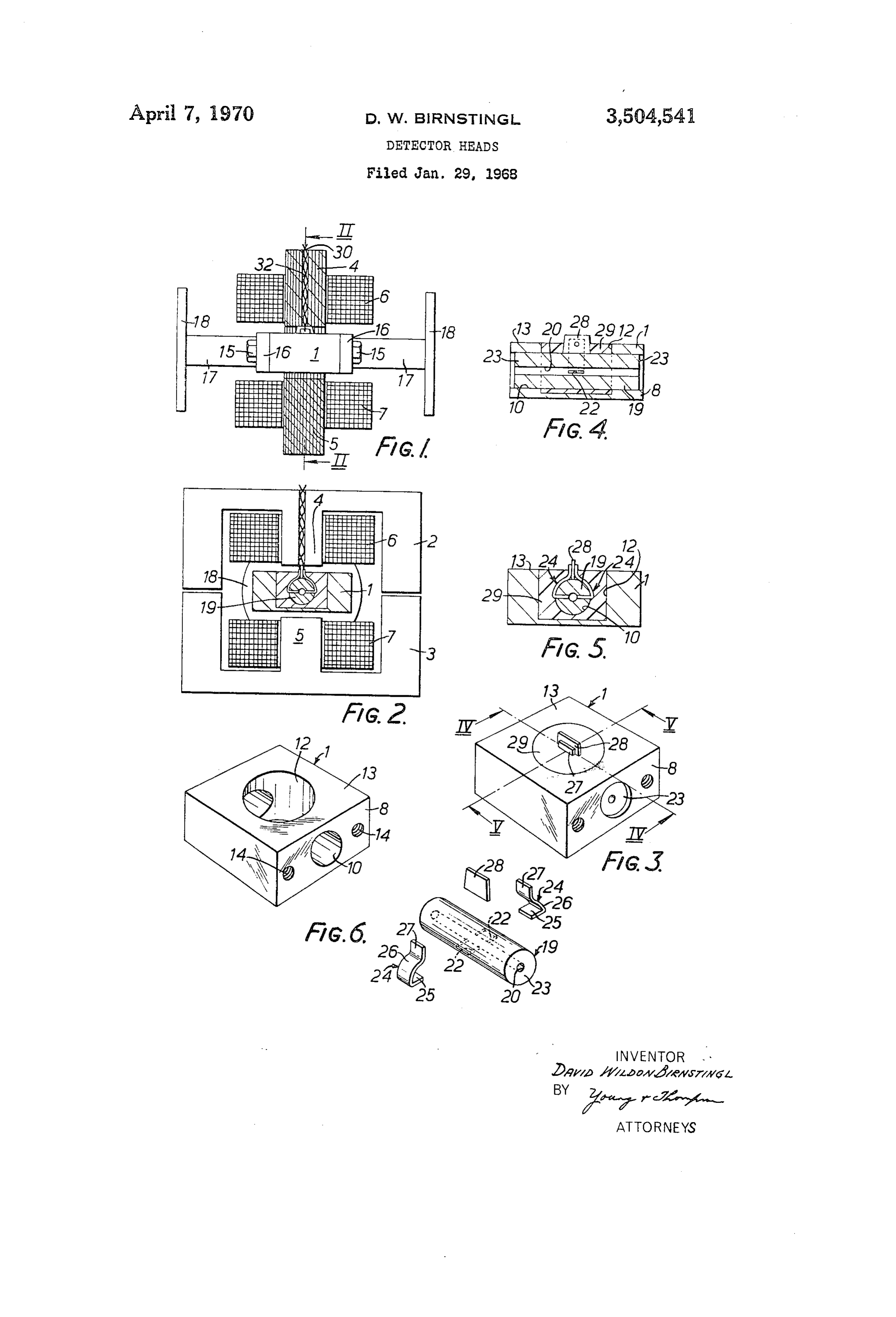
FIGURE 2 is a sectional view on the line II II of
FIGURE 3 is a perspective view of a sub-assembly of the head,
FIGURE 6 is a perspective “exploded” view of the sub assembly.
Page 1drawing sheetscan →
Page 2scan →
Detector heads
David Wildon Birnsting, Stroud, England, assignor to Mawdsley's Limited, Dursley, England
Claims priority, application Great Britain, Feb. 4, 1967,
Abstract of the disclosure
An electromagnetic flowmeter head comprises a bored out non-magnetic metal block within which is secured, by an insulating material moulded in situ, a tube for con 5 taining the liquid flow and two opposed electrodes pre formed from metal strip and presenting opposed elongated contact surfaces the longitudinal axes of which are paral lel to the longitudinal axis of the tube.
This invention relates to detector heads of the type embodying at least one electrode for electrical contact with a flowing liquid. It is of particular application to Such heads of small bore, for example of less than 4 25 inch diameter, and is of special but by no means exclu sive application to the detector head of an electromag netic flowmeter employing the usual arrangement of two diametrically opposed electrodes.
Detector heads of the type concerned normally em 30 ploy electrodes having a circular contact area, and with Small bores there is a tendency for gas bubbles to form on the electrode surface. This is particularly so at zero flow conditions, and once a small bubble forms it tends to provide a nucleus at which further gas entrained in the liquid is released so that the bubble increases in size and may completely cover and insulate the electrode. One of the objects of the invention is to overcome or at least materially reduce the problem of bubble formation: an other object is to improve the electrical characteristics 40 as will be made clear hereinafter.
According to one aspect of the invention a detector head has a through bore for the liquid flow and an elec trode mounted in the wall of the bore with a contact sur 45 face which is elongated with a longitudinal axis which extends generally parallel to the longitudinal axis of the through bore. It has been found that the use of elec trodes elongated in this manner, particularly with very Small bores, materially reduces bubble formation; even 50 if small bubbles form they break away and leave the electrode before reaching a sufficient size to cover the Surface.
AS applied to an electromagnetic flowmeter the head will employ two diametrically opposed electrodes of the described elongated form and each electrode is con veniently fabricated from metal strip and positioned in a corresponding one of two longitudinally extending slots in the Wall of the bore so that one edge of the strip is ex posed within the bore for electrical contact with a liquid 60 passing through the bore. In a preferred construction the bore is provided by a tube of an insulating material and the tube, together with the electrodes in position, is re tained in a bored-out non-magnetic metallic block by means of an insulating material which is moulded in 65 situ So as to locate and secure both the electrodes and the tube with respect to the block. Each strip conveniently extends externally of the tube so that an outer end thereof projects through the moulded-in insulating material and is accessible for electrical connection. 70 A suitable insulating material for casting or moulding is an epoxy resin, and the block may have a through
Patented Apr. 7, 1970 bore for accommodating the tube and an intersecting blind bore which extends from one side of the block and in which the insulating material is moulded.
Alternatively, the electrodes may be cast or moulded in position in a block of insulating material the bore of which is subsequently cleaned out to size, for example by reaming, with the sizing operation exposing the final elongated electrode contact area.
According to another aspect of the invention an elec tromagnetic flowmeter head comprises a bored-out non magnetic metal block within which is secured, by an in sulating material moulded in situ, a tube for containing the liquid flow and at least one electrode extending through an aperture in the tube wall for electrical contact with the liquid flow. As before, the electrode is prefer ably one of two such opposed electrodes elongated axi ally of the tube.
The increased contact area of the electrodes provides the improved electrical characteristics previously referred to, and this results from the lowered electrode to earth and inter-electrode impedances which are obtained. These impedances can be considered as forming limbs of po tential dividers from which stray pick-up voltages and the electrode signal voltage are respectively fed to the asso ciated measuring circuit, and lowering the impedances results in an increased effective signal voltage and a de creased effective pick-up voltage.
The invention will now be further described with ref erence to the accompanying drawings which show, by way of example, a small bore electromagnetic flowmeter head embodying the invention. In the drawings: FIGURE 1 is a side view of the head, with parts shown in longitudinal axial sectional view,
FIGURE 2 is a sectional view on the line II II of
Figure 1,
FIGURE 3 is a perspective view of a sub-assembly of the head,
FIGURES 4 and 5 are respectively sectional views on the lines IV-IV and V V of FIGURE 3, and
FIGURE 6 is a perspective “exploded” view of the sub assembly.
The head comprises a non-magnetic metallic block 1 surrounded by two laminated metal yoke members 2 and 3 which have central limbs 4 and 5 around which are wound energising coils 6 and 7 respectively. When the coils are energised, magnetic flux passes through the block 1 and between the central limbs 4 and 5, the E-shaped yoke members 2 and 3 providing return magnetic paths for the flux. In FIGURE 2 air gaps are shown between the two members 2 and 3, these gaps merely providing small dimensional tolerances which facilitate connection of the members 2 and 3 to a support structure (not shown).
As shown particularly in FIGURE 6, the block 1 has rectangular end faces 8 between which extends a central through bore 10 the longitudinal axis of which is perpen dicular to and intersects the axis of a relatively large di ameter blind bore 12 bored from a top face 13 of the block. Each end face 8 is provided with tapped bores 14 for securing, by means of connecting screws 15 (FIG URE 1), a flanged inner end 16 of a corresponding one of two short lengths of connecting pipe 17 the outer ends of which have connecting flanges 18 for bolting into a pipeline (not shown). The longitudinal axes of the lengths of pipe 17 are aligned with the longitudinal axis of the bore 10.
A thick walled tube 19 is of a solid insulating material and has a central bore 20 for accommodating the liquid flow and two opposed slots 22 which are elongated axially of the bore 20 and which break into the latter. On assem bly of the head, the tube 19 is inserted into the bore 10, 3 within which it is a close fit, with each face 23 of the tube 2. An electromagnetic flowmeter head according to 19 being slightly recessed behind the corresponding end claim 1, wherein said body is a cylindrical tube of an face 8 of the block 1, as shown in FIGURE 4. The insulating material.
recesses thus formed accommodate O-rings or sealing 3. An electromagnetic flowmeter head according to Washers which are inserted between each end face 23 claim 2 and including a bored-out non-magnetic metallic and the corresponding flange 16 on assembly of the head. block within which the tube and the electrodes are retained The blind bore 12 renders the two slots 22 accessible for by an insulating material.
the respective insertion of two electrodes 24 performed 4. An electromagnetic flowmeter head according to from metal strip. claim 3, wherein the insulating material is moulded in An inner end 25 of each electrode 24 fits within the O situ.
corresponding slot 22 so that the electrode 24 presents 5. An electromagnetic flowmeter head according to an elongated contact surface within the bore. An inter claim 3, wherein the block has a through bore accommo mediate curved portion 26 of each electrode fits closely dating the tube and a mutually perpendicular and inter against the outer surface of the tube 19 and adjoins an secting blind bore within which the electrodes are dis outer end 27 which, as shown in FIGURE 5, projects 15 posed.
beyond the plane of the top face 13 of the block 1. An 6. An electromagnetic flowmeter head according to insulating spacer 28 is positioned between the two outer claim 5, wherein each electrode strip has an inner end ends 27, after which the space within the blind bore 12 within the corresponding slot and terminating in the and surrounding the tube 19 and electrodes 24 is filled associated contact surface, an intermediate portion which with an insulating material 29, such as an epoxy resin, isof ofthearcuate shape and fits against an external portion tube and an outer end which is accessible for which is thereby moulded in situ and acts to retain the tube 19, the electrodes 24 and the spacer 28 in position. external connection.
In addition, the insulating material 28 provides insulation 7. An electromagnetic flowmeter head according to between the block 1 and the electrodes 24, the extremities claim 6, wherein said two outer ends are insulated from of the outer ends 27 of which are accessible for connec one another by means of a spacer strip. tion to an electrical circuit (not shown), the connecting 8. An electromagnetic flowmeter head according to wires 30 (FIGURES 1 and 2) being soldered to the elec claim 3, wherein the block is surrounded by two E-shaped trodes 24 and led out as a twisted pair through an aper pole pieces, two centre limbs of which lie on diametrically ture 32 in the limb 4. Apart from the provision of the opposite sides of the bore and support field coils, aperture 32 in the limb 4, the two members 2 and 3 are 30 References Cited identical.
I claim: UNITED STATES PATENTS 1. An electromagnetic flowneter head comprising a 1,249,530 12/1917 Smith et al. body with a through bore for accommodating liquid flow 3,034,002 5/1962 Carlson. in a direction paralled with a longitudinal axis of the bore, 35 3,343,414 9/1967 Cason -------------- 73-194 the body having a wall through which extend two slots 3,387,492 6/1968 Mannherz et al. ------ 73-194 which break into the bore or mutual opposite sides of the latter, and two electrodes formed of metal strip and re FOREIGN PATENTS spectively located in the two slots, each electrode having 1,016,923 1/1966 Great Britain. a contact surface flush with the bore and provided by 40 OTHER REFERENCES an end surface of a strip providing the corresponding one of said electrodes, with the two contact surfaces being German printed application, No. 1,220,160, June 1966. mutually opposed and elongated in directions parallel to said axis. CHARLES A. RUEHL, Primary Examiner
Provenance
- Collection
- Patents citing this work
- Pages
- 3
- Method
- pdftotext (the PDF's own text layer) + pdftoppm 300dpi page scans
- Patent office record
- patents.google.com →
- Source
- Google Patents citing-documents table
- Assignee
- Mawdsley S Ltd
- Published
- 1970-04-07
- Transcribed from
- patentimages.storage.googleapis.com →