

patent · US3511756A
Flash evaporation with series arranged with solar heating zone
12 May 1970
Text
Drawings
Page 1drawing sheetscan →
Page 2drawing sheetscan →
Page 3scan →
United States Patent Office 3,511,756 Patented May 12, 1970 following detailed description of the invention when read
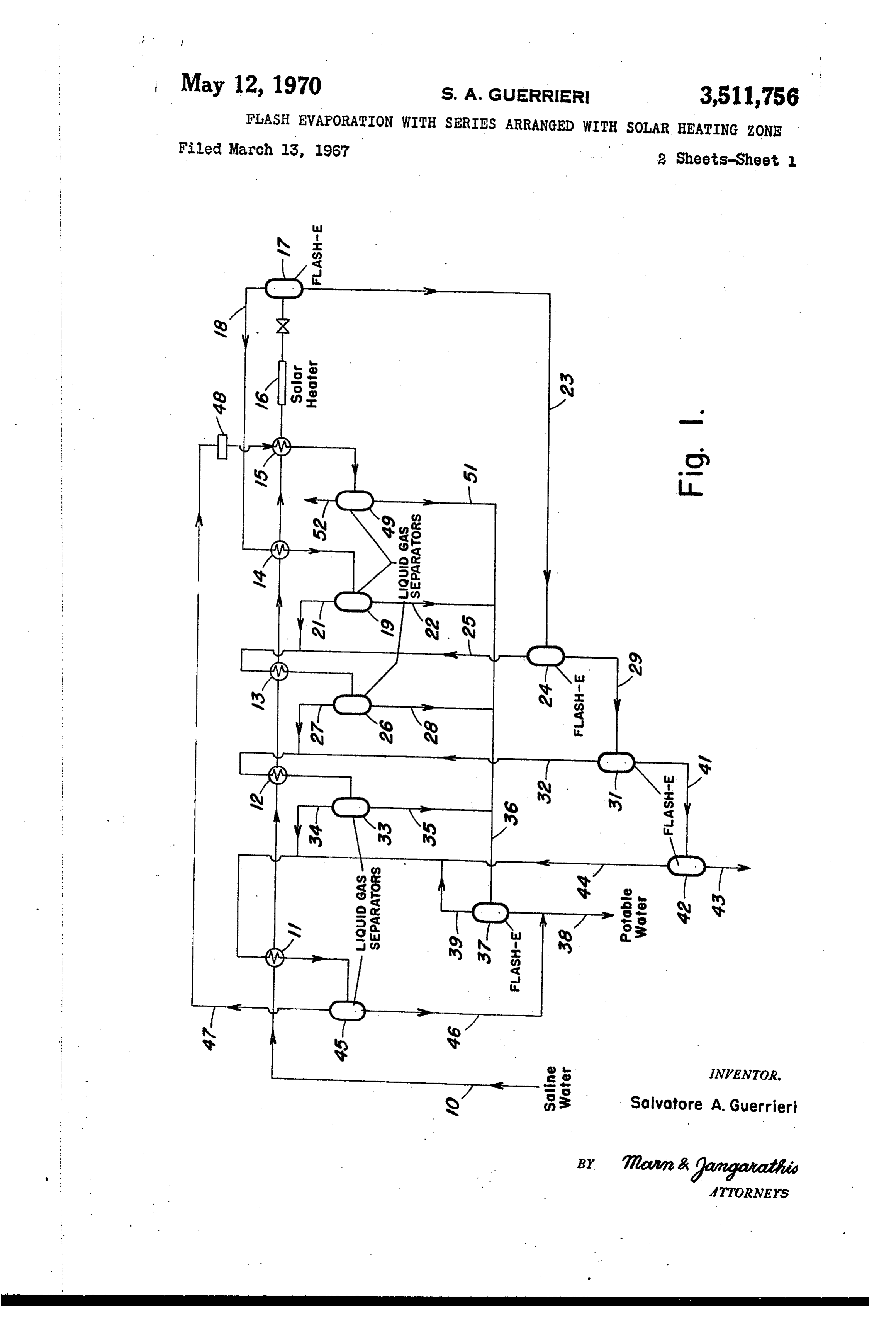
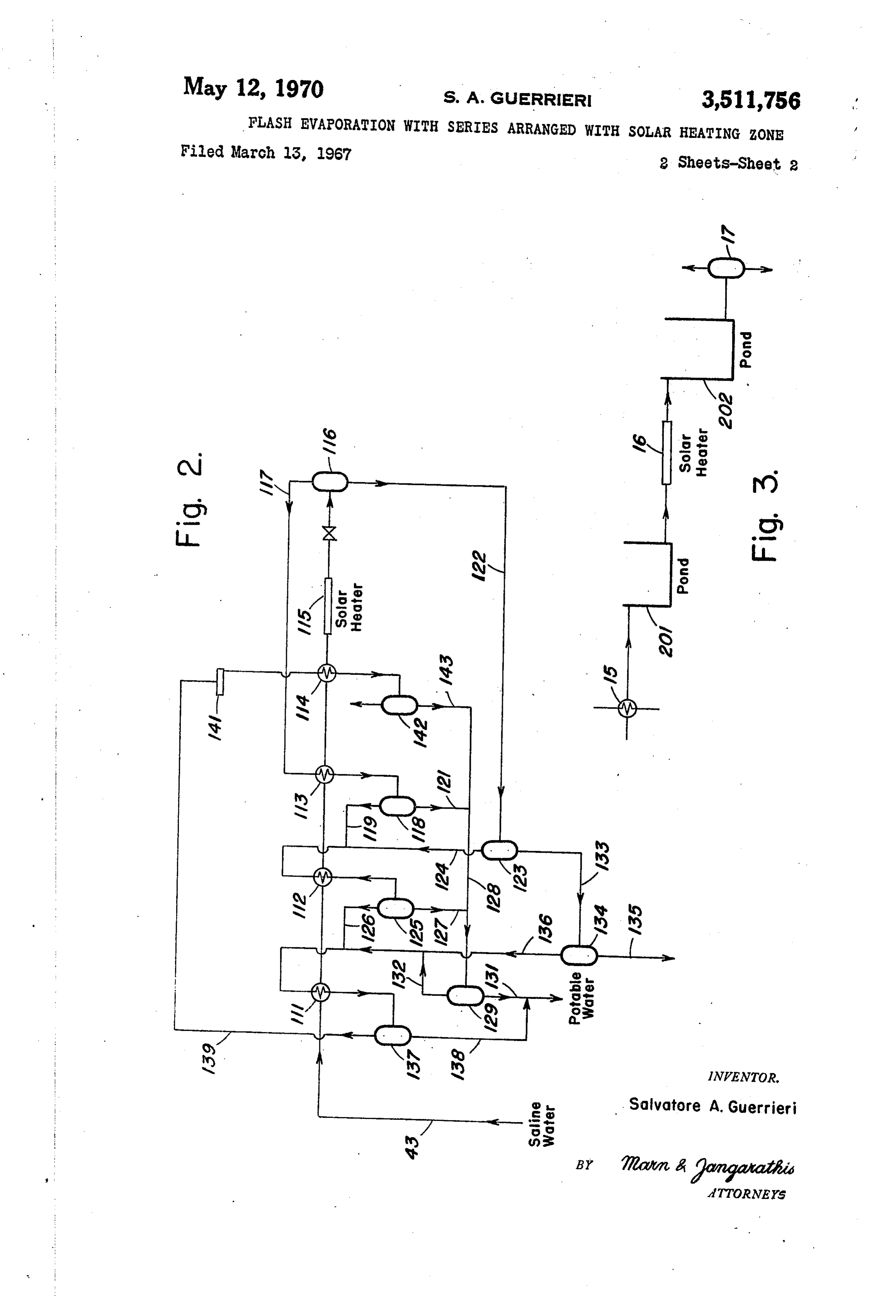
FLASH EVAPORATION WITH SERIES ARRANGED with reference to the accompanying drawings wherein: WITHSOLAR HEATING ZONE FIG. 1 is a simplified schematic flow diagram of an Salvatore A. Guerrieri, Rowayton, Conn. (% The Lum embodiment of the invention;
mus Company, 385 Madison Ave., New York, N.Y. 5 FIG. 2 is a simplified schematic flow diagram of an 10017 other embodiment of the invention; and 'Filed Mar. 13, 1967, Ser. No. 622,622 FIG. 3 is a simplified schematic partial flow diagram Int, C. B01d 3/06; C02b 1/06 of a modification of the embodiment of FIG. 1. U,S. CI. 203—11. 5 Claims The objects of this invention are broadly accomplished 10 by heating a liquid with solar energy, without change of
ABSTRACT OF THE DISCLOSURE phase, followed by flashing the heated liquid to effect evaporation. More particularly, the liquid which has been
A process and apparatus for producing potable water heated by solar energy without change of phase, is passed from saline water wherein the saline water is heated in through a series of below atmospheric pressure flash a solar heater without change of phase and then flashed 15 evaporation stages of decreasing temperature, with the in a plurality of below atmospheric pressure stages of liquid vapors from each stage being condensed and re decreasing temperature and pressure. The flashed vapors covered. In a distinct embodiment of the invention, the are condensed and recovered as potable water. The saline unvaporized liquid recovered from the last flash vapori water recovered from the last stage may be heated in a zation stage is reheated by solar energy and again passed solar heater without change of phase and flashed in an 20 through a series of below atmospheric pressure flash other plurality of below atmospheric pressure stages of evaporation stages with the second series of flash evapori decreasing temperature and pressure, containing one less zation stages containing less stages than the first series. stage than the first plurality of stages. The system may The invention will be described in more detail with ref be adapted to around the clock operation by passing a fuli 25 erence to the purification of saline water, but it is to be day water requirements through the solar heater during understood that the invention is equally applicable to the the sunny hours and storing a portion thereof as feed evaporation of liquids other than saline water. The spe for the flash stages during non-Sunny hours. cific equipment to be employed is schematically illus trated and equipments such as valves, pumps, and the like are not shown to simplify the description of the invention.
This invention relates to the evaporation of liquids and 30 The choice of specific equipment in appropriate places is particularly directed to the production of potable Water should be readily apparent to those skilled in the art from from brackish water and brines. the teachings of the invention. Thus, the solar heater em Recently, there have been many processes directed to ployed could be any one of a wide variety of solar heaters the production of potable water from brackish water and known in the art, e.g., a solar heater having a covering brines, hereinafter generically referred to as "saline wa membrane which is both highly translucent to incident ter,' and in particular, to the use of solar heat to recover solar radiation and substantially opaque to low tempera potable water from saline water. To date, the processes ture radiation from the pool of water being heated there employing solar heat are based on a humidification-de in. The membrane should also have a low thermal con humidification operation wherein saline water flows ductivity to minimize both conductive and convective heat through basins, provided with a translucent membrane 40 losses. A covering membrane comprised of a plurality of cover, and is heated therein by solar radiation. An air adjacent membranes separated by a small air space is space is provided between the surface of the water and especially effective in minimizing heat losses. the membrane and the air flowing therethrough, in con Referring to FIG. 1, saline water in line 10 is succes tact with the warm water, is humidified. The humidified 45 sively passed through heat exchangers 11, 12, 13 and 14 air is passed to a second zone wherein the air contacts a wherein the saline water is heated to successively higher cooler membrane to condense water therefrom. The sec temperatures by indirect heat transfer with vapors with ond Zone is provided with suitable collecting troughs and drawn from a plurality of flash evaporators, as herein channels to collect and pass the water to storage. after more fully described. The now heated water is The above described system is not suitable for low 50 passed through another heat exchanger 15, and further cost design because of the problems in designing the mem heated therein by indirect heat transfer with non brane and dehumidifier and the lack of a suitable method condensible gases being passed to a vent, as hereinafter for recovering latent heat. In regard to the latter, it has more fully described. The heated water from heat been estimated that approximately one thousand B.t.u. exchanger 15 is then passed through a solar heater, sche of solar heat must be supplied to vaporize one pound of 55 matically indicated at 16, and heated therein, without water; and at a latitude of 35 north, where solar radia change of phase, by solar radiation. tion incident on one square foot is about 360 B.t.u. per The heated water withdrawn from solar heater 16 is in hour, about three square feet of surface are required to troduced into a flash evaporator 17 operating at a pres evaporate one pound of water per hour, operating at sure below atmospheric pressure to effect partial vapor 100% efficiency. It should be readily apparent that in al 60 ization thereof. Flashed vapor, including water vapor and lowing for inefficiencies and lower incident solar energy non-condensible gases contained in the saline water, at other hours, the evaporation area will have to be in is withdrawn from flash evaporator 17 through line 18 creased considerably, and passed through the heat exchanger 14 in an indirect An object of this invention is to provide an improved heat transfer relationship with the saline water feed flow process and apparatus for evaporating liquids. 65 ing therethrough. As a result of the indirect heat transfer Another object of this invention is to provide an im between the saline water and flashed vapor in heat proved process and apparatus for using solar heat in eva exchanger 14, a portion of the water vapor contained porating liquids. in the flashed vapor is condensed. The condensate and Water Saturated non-condensible gases are passed to a
A further object of this invention is to provide a proc separator 19 to recover condensate. The water saturated ess and apparatus for producing potable water by the use 70 non-condensible of solar heat. gas is withdrawn from separator 19 These and other objects will become clear from the through line 21 for combination with vapors withdrawn . from the next lower flash evaporator. Condensate is 4 withdrawn from the separator 19 through line 22 for through line 51 and combined with the condensate in line further treatment, as hereinafter more fully described. 36, for cooling and passage to storage, as hereinabove Unvaporized saline water is withdrawn from flash more fully described. The non-condensible gases are evaporator 17 through line 23 and introduced into a vented from the separator 49 through line 52. flash evaporator 24, operating at a temperature lower In accordance with a second embodiment of the in than flash evaporator 17, to effect further vaporization vention, the brine withdrawn from the last flash evapo thereof. Flashed vapor is withdrawn from the flash rator 42 through line 43, is treated in a manner similar evaporator 24 through line 25, combined with the water to the one described hereinabove, using one less flash saturated non-condensible gas in line 21 and passed evaporator. Referring to FIG. 2, unvaporized Saline wa through heat exchanger 13 wherein a portion of the water 0 ter withdrawn from flash evaporator 42 through line 43 vapor is condensed by indirect heat transfer with the is successively passed through heat exchangers 111, 112 saline water feed flowing therethrough. Condensate and and 113 to effect heating thereof by indirect heat trans water saturated non-condensible gas withdrawn from fer with vapors withdrawn from a plurality of flash heat exchanger 13 are introduced into a separator 26 to evaporators, as hereinafter more fully described. The recover condensate therefrom. The water saturated non now heated water is passed through another heat ex condensible gas is withdrawn from the separator 26 changer 114, and further heated therein by indirect heat through line 27 for combination with vapors withdrawn transfer with non-condensible gases being passed to a from the next lower flash evaporator. Condensate is with vent, as hereinafter more fully described. The heated drawn from the separator 26 through line 28 for further water withdrawn from the heat exchanger 114 is then treatment, as hereinafter more fully described. 20 passed through a solar heater, schematically indicated as Unvaporized saline water is withdrawn from flash 115, and heated therein, without change of phase, by evaporator 24 through line 29 and introduced into a flash solar radiation.
evaporator 31, operating at a temperature lower than Heated water withdrawn from solar heater 15 is in flash evaporator 24, to effect further vaporization thereof. troduced into a flash evaporator 116, operating at a Flashed vapor is withdrawn from the flash evaporator 25 pressure below atmospheric pressure, to effect partial 31 through line 32, combined with the water saturated vaporization thereof. Flashed vapor including water non-condensible gas in line 27 and passed through heat vapor and non-condensible gases, is withdrawn from exchanger 12 wherein a portion of the water vapor is flash evaporator 116 through line 117 and passed condensed by indirect heat transfer with the saline water through heat exchanger 113 wherein a portion of the feed filowing therethrough. Condensate and water satu 30 water vapor is condensed by indirect heat transfer with rated non-condensible gas withdrawn from heat exchanger the saline water feed flowing therethrough. Condensate 12 are introduced into a separator 33 to recover con and water saturated non-condensible gases withdrawn densate therefrom. The water saturated non-condensible from heat exchanger 113 are introduced into a separa gas is withdrawn from the separator 33 through line 34 tor 118 to recover condensate therefrom. The water sat for combination with vapors withdrawn from the next 35 urated non-condensible gas is withdrawn from separator lower flash evaporator. Condensate is withdrawn from 118 through line 119 for combination with vapors with the separator 33 through line 35 for further treatment, drawn from the next lower flash evaporator. Condensate as hereinafter more fully described. is withdrawn from the separator 118 through line 121 The condensate in lines 22, 28 and 35 are combined in line 36 and introduced into a flash evaporator 37 to 40 for further treatment, as hereinafter more fully de scribed.
effect flash cooling thereof. The unvaporized condensate Unvaporized saline water is withdrawn from flash is withdrawn from the flash evaporator 37 through line evaporator 116 through line 122 and introduced into a 38 and passed to storage (not shown). Flashed vapors are withdrawn from the flash evaporator 37 through line flash evaporator 123, operating at a temperature lower than flash evaporator 116, to effect further vaporization 39 for combination with the flashed vapors withdrawn thereof. Flashed vapor is withdrawn from the flash evap from the last saline water flash evaporator, as herein after more fully described. orator 123 through line 124, combined with the water Unvaporized saline water is withdrawn from the flash saturated non-condensible gas in line 119 and passed evaporator 31 through line 41 and introduced into a water through heat exchanger 112 wherein a portion of the flash evaporator 42, operating at a temperature lower vapor is condensed by indirect heat transfer with than flash evaporator 31, to effect further vaporization 50 the saline water feed flowing therethrough. Condensate thereof. Unvaporized saline water is withdrawn from and water saturated non-condensible gas withdrawn from the flash evaporator 42 through line 43 for rejection or heat exchanger 112 are introduced into a separator 125 further treatment in accordance with a second embodi to recover condensate therefrom. The water saturated ment of the invention. Flashed vapor is withdrawn from non-condensible gas is withdrawn from the separator the flash evaporator 42 through line 44, combined with 55 125 through line 126 for combination with vapors with the water vapor in line 39 and the water saturated non drawn from the next lower flash evaporator. Condensate condensible gas in line 34. The combined stream in line is withdrawn from the separator 125 through line 127 for 44 is passed through heat exchanger 11 wherein a por further treatment, as hereinafter more fully described. tion of the water vapor is condensed by indirect heat The condensate in lines 121 and 127 is combined in transfer with the saline water feed flowing therethrough. 60 line 128 and introduced into a flash evaporator 129 to Condensate and water saturated non-condensible gas with effect flash cooling thereof. Unvaporized condensate is drawn from heat exchanger 11 are introduced into a withdrawn from the flash evaporator 129 through line separator 45 to recover condensate. The condensate is 131 and passed to storage (not shown). Flashed vapors withdrawn from separator 45 through line 46 and com are withdrawn from the flash evaporator 129 through bined with the condensate in line 38 being passed to 65 line 132 for combination with the flashed vapors with storage (not shown). drawn; from the last saline water flash evaporator as Water saturated non-condensible gas is withdrawn from hereinafter more fully described.
separator 45 through line 47, compressed to about atmos Unvaporized saline water is withdrawn from flash pheric pressure by compressor 48 and passed through evaporator 123 through line 133 and introduced into a heat exchanger 15 wherein the water is condensed at the 70 flash evaporator 134, operating at a temperature lower higher pressure by indirect heat transfer with the saline than flash evaporator 123, to effect further vaporization water feed flowing therethrough. The condensate and thereof. Unvaporized saline water is withdrawn from the non-condensible gas is introduced into a separator 49 to flash evaporator 134 through line 135 for rejection or recover condensate. further treatment in accordance with a distinct embodi The condensate is withdrawn from separator 49 75 ment of the invention. Flashed vapor is withdrawn from 5 the flash evaporator 134 through line 136 and combined system. Accordingly, during both the sunny and dark with the water vapor in line 132 and the water saturated hours, preheated water withdrawn from heat exchanger non-condensible gas in line 126. The combined stream 15 is always introduced into pond 201 and heated water in line 136 is passed through heat exchanger 111 where is always withdrawn from pond 202 and passed to the in a portion of the water vapor is condensed by indirect evaporation system enabling the system to operate con heat transfer with the saline water feed flowing there tinuously and at a constant rate. through. Condensate and water saturated non-condensi The above modifications and numerous other modi ble gas withdrawn from heat exchanger 111 are intro fications should be readily apparent to those skilled in duced into a separator 137 to recover condensate there the art from the teachings of the invention. from. The condensate is withdrawn from separator 137 10 The following illustrates a specific embodiment of the through line 138 and combined with the condensate in invention, but the scope of the invention is not to be line 131 being passed to storage (not shown). limited thereby:
Water saturated non-condensible gas is withdrawn EXAMPLE from separator 137 through line 139, compressed to In accordance with the embodiment illustrated in FIG. about atmospheric pressure by compressor 141 and passed through heat exchanger 114 wherein the water is1, passed 100 pounds of saline water at a temperature of 60° F. successively through heat exchangers 11, 12, vapor is condensed at the higher pressure by indirect heat 13, 14 and 15 to raise the temperature of the saline water transfer with the saline water feed flowing therethrough. to 78° F, 96 F., 114 F., 132° F. and 136 F., respec Condensate and non-condensible gas withdrawn from hcat cxchangcr 114 arc introduccd into scparator 142 20 tively. The heated saline water is then passed through Solar heater 16 wherein the temperature thereof is raised to recover condensate therefrom. The condensate is with to 160 F. without change of phase. drawn from separator 142 through line 143 and com The heated saline water is then successively passed bined with the condensate in line 128, for cooling and through flash evaporators 17, 24, 31 and 42, operating at passage to storage as hereinabove more fully described.
The non-condensible gases are vented from the separator 25 temperatures of 140 F., 120° F., 100 F. and 80° F., respectively, with two pounds of water vapor being 142 through line 144. flashed in each evaporator. The condensing heat exchang Numerous modifications and variations of the inven ers and separators for each evaporator operate at the tion are possible without departing from the scope there same temperature as their respective evaporator, and ac of. Although the invention has been particularly de cordingly, vapor condensation is effected without cooling. scribed with reference to four flash stages in FIG. 1, 30
Thus, condensation and separation is effected in sepa this is not necessarily the optimum number of stages.
Thus, as the number of flash stages increase, both the rator 19 at 140° F., in separator 26 at 120° F., in sepa water recovery per pound of saline water feed and the The vapor withdrawn from separator 45 in the last heat economy improve because of an increase in the temperature of the feed preheat. However, as the num 35 isflash evaporation stage is at a temperature of 80 F., and compressed to one atmosphere in compressor 48. The ber of flash stages increase the temperature difference between the flashed vapors and the saline water feed water vapor in the compressed vapor is condensed and separated in separator 49 at a temperature of 140 F.
flowing through the heat exchangers, which function as The condensate from separators 49, 19, 26 and 33 is both a condenser for the flashed vapors and as a heater 40 flash for the feed, decreases and thus, heat exchangers of bined cooled to 80° F. in flash evaporator 37 and com larger surface area must be employed. Hence, for any at a temperature of 80°withdrawn with condensate from the separator 45
F. The total yield of condensate given set of conditions, the optimum number of flash (potable water) is 8 pounds.
stages may be readily calculated. 92 pounds of unvaporized saline water is withdrawn In another modification, successive flash systems of from decreasing flash evaporation stages may be employed F. andthepassed last flash evaporator 42 at a temperature of 80° to the flash evaporation system illustrated with the last flash system containing only one flash in FIG. 2.
stage. The use of successive flash systems of decreasing stages increases potable water recovery per pound of F. The 92 pounds of saline water at a temperature of 80° is passed successively through heat exchangers 111, saline water feed, but also increases the amount of 112, 113 and 114 to raise the temperature of the saline * Solar heat required per pound of recovered water. Once 50 water feed to 98° F., 116 F., 134° F. and 136° F., re again, for any given set of conditions the optimum num spectively. The heated saline water is then passed through ber of flash systems of decreasing flash stages may be Solar heater 115 wherein the temperature thereof is raised readily calculated. to 160 F. without change of phase. In a further modification, a reservoir may be pro The heated saline water is then successively passed vided for hot saline water so that the systems illustrated through flash evaporators 116, 123 and 134, operating at in FIGS. 1 and 2 may operate around the clock. Refer temperatures of 140 F., 120° F., and 100° F., and 100° ring to FIG. 3, there is shown by way of illustration a F., respectively, with 1.8 pounds of water vapor being portion of the flash evaporation system of FIG. 1, pro flashed in each evaporator. The condensing heat ex vided with heat exchanger 15, solar heater 16, and changers and separators for each evaporator operate at flash evaporator 17 which function as described with 60 the same temperature as their respective evaporator, and reference to FIG. 1 and further provided with a storage accordingly, vapor is condensed without cooling. Thus, pond 201 and a storage pond 202. condensation and separation is effected in separator 118 In operation, during the Sunny hours, the solar heater at 140 F., in separator 125 at 120° F., and separator 137 16 operates at full capacity to heat a full day water feed requirement for the evaporation system. Conse 65 at The 100 F.
vapor withdrawn from separator 137 in the last quently, during the sunny hours, a portion of the water flash evaporation withdrawn from the solar heater 16 is accumulated in and is compressed stage, to one is at a temperature of 100° F.
atmosphere, in compressor 141.
pond 202. The water withdrawn from heat exchanger The Water vapor in the compressed 15, during the sunny hours, is introduced into pond 201 and separated in separator 142, atvapor a is condensed temperature of and water is passed from pond 201, through the solar 70 140° F.
heater 16 to the pond 202. During the dark hours, pre heated water withdrawn from the heat exchanger 15 is andThe125condensate withdrawn from separators 142, 118 accumulated in pond 201 and the heated water which was and combined with thetocondensate is flash cooled 100 F. in flash evaporator 129 withdrawn from the accumulated in pond 202 during the sunny hours is Separator 137 at a temperature of 100° withdrawn thereform and passed through the evaporation 75 condensate (potable water) is 5.4 pounds.F. The yield of
Page 6scan →
86.6 pounds of unvaporized saline water is withdrawn liquid feed to the solar heating Zone subsequent to from flash evaporator 134 at a temperature of 100' F. the passing of the liquid feed through the condensing and may be further treated in another flash evaporation zones to effect recovery of additional distillate from system having two flash evaporation stages. said non-condensible gas. The process and apparatus of this invention are an 2. The process as defined in claim 1 and further com improvement over those previously used for recovery of 5 prising:
potable water from brines, and particularly those which recovering condensate from the last flash evaporation employed solar energy as a source of heat. The solar zone and subjecting the saline water to steps (a), heaters employed in accordance with the invention are (b), (c), (d) and (e), using one less flash evapora considerably simpler and less expensive than those used 10 tion zone in step (c).
in the humidification processes in that there is no neces 3. The process as defined in claim 1 wherein the con sity either for collecting troughs and the like or for densate from each condensation zone is passed to a con specially designed translucent covers which permit a non densate flashing zone to effect flash cooling thereof and condensible carrier, gas to flow over a pool of water. the vapors from said condensate flashing zone are com Moreover, in accordance with the invention, in a four 5 bined with the vapors from the last flash evaporation zone. stage flash system only about three hundred B.t.u.'s/lb. of 4. The process as defined in claim 1 wherein the liquid recovered water is required in contradistinction to the is saline water.
1000 B.t.u./lb. required in the humidification processes. 5. An evaporation system for effecting evaporation of Although the heat requirement per pound of water in a liquid by solar radiation comprising: creases when flash systems having a successively decreas 20 (a) a series of flash evaporators;
ing number of flash stage are employed, the heat require (b) means for passing liquid from a first evaporator ment for such an operation, about 470 B.t.u.'s/lb., is still through each evaporator in the series; considerably less than the heat requirements for the (c) a solar heater;
humidification processes. In addition, the use of, for (d) means to pass liquid from said solar heater to said example, four successive flash systems having four, three, 25 first evaporator including means for storing liquid two and one flash stage results in a water recovery of 18.5 from the solar heater;
lbs. per pound of saline water as compared to 8 lbs./lb. (e) a condenser for each evaporator comprising means feed for a single four-stage system. for passing said liquid in indirect heat exchange with Numerous modification and variations of the present vapors withdrawn from the evaporators; invention are possible in light of the above teachings. It 30 (f) means for passing vapor from each evaporator is therefore to be understood that within the scope of to each condenser respectively; the appended claims the invention may be practiced (g) means for recovering condensate from each con otherwise than as particularly described, denser;
What is claimed is: (h) means for passing feed liquid through each con 1. In the evaporation of a liquid by solar radiation, the 35 denser in series;
improved process comprising: (i) means for storing preheated feed liquid after (a) passing the liquid in series through a plurality of passing through the last of said condensers; and vapor condensation zones as hereinafter defined in step (d), to effect heating of the liquid to successively (i) means for passing the thus preheated stored liquid to said heater.
higher temperatures by indirect heat transfer with 40 flashed vapors withdrawn respectively from a plural References Cited ity of flash evaporators; UNITED STATES PATENTS (b) passing the resultant heated liquid through a heat exchanger Zone as hereinafter defined in step (g) and 2,445,350 7/1948 Ginnings ----------- 202-172 then through a solar heating zone wherein the liquid 45 3,1 19,752 1/1964 Checkovich ---------- 203-11 is heated by solar radiation without effecting vapor 3,165,452 1/1965 Williams --------- 203-11 ization thereof; 3,168,450 2/1965 Black ----------- 203-10 X (c) passing at least a portion of the liquid from step 3,219,553 1 1/1965 Hughes ---------- 203-11 ? (b) through the plurality of flash evaporators de 3,320,137 5/1967 Jebens et al. 203-11 ? fined in step (a) comprising below atmospheric pres 50 3,248,307 4/1966 Walford ------------ 203-11 Sure flash evaporation zones of decreasing tempera 3,261,766 7/1966 Sherwood ----------- 203-1 ture and pressure to produce vapors which are with 3,305,456 2/1967 Broughton -------- 203-100 ? drawn respectively therefrom; 2,213,894. 9/1940 Barry.
(d) passing the vapors from each flash evaporation 2,490,659 12/1949 Snyder --------- 202 -205 X Zone through its respective condensation zone to in 3,076,096 1/1963 Bachmann -------- 202-234 X directly heat the liquid feed as defined in step (a) 3,232,846 2/1966 Kimmerle -------- 202-234 X and cool the vapor to condense distillate; 3,257,290 6/1966 Starmer ---------- 203 -11 ? (e) recovering the distillate from step (d); FOREIGN PATENTS (f) combining non-condensed gas from each condensa 60 tion Zone with vapors from the subsequent flash 937,623 9/1963 Great Britain.
evaporation zone for passage through its condensa tion Zone to thereby effect recovery of additional NORMANYUDKOFF, Primary Examiner distillate from the non-condensed gas; and F. E. DRUMMOND, Assistant Examiner (g) compressing the non-condensed gas from the last 65 condensation zone and passing the compressed gas e U.S. Cl. X.R.
in an indirect heat transfer relationship with the 202-173; 203-26, 88; 252-234
Provenance
- Collection
- Patents citing this work
- Pages
- 6
- Method
- pdftotext (the PDF's own text layer) + pdftoppm 300dpi page scans
- Patent office record
- patents.google.com →
- Source
- Google Patents citing-documents table
- Assignee
- Lummus Co
- Published
- 1970-05-12
- Transcribed from
- patentimages.storage.googleapis.com →