

patent · US3645661A
Burner control system
29 February 1972
Text
Page 1bibliographic recordscan →
Goodman
54 BURNER CONTROL SYSTEM
72 Inventor: Kenneth C. Goodman, Columbus, Ohio Assignee: Ranco Incorporated, Columbus, Ohio
U.S.C...................................................431/24,431778 51 int. Cl............................................................F23n 5700 58 Field of Search............................431/24, 69, 7, 78-80;
UNITED STATES PATENTS
3,291,183 12/1966 Fairley.................................431/78 X 3,463,600 8/1969 Axmark... ...431/79 X 3,086,583 4/1963 Reichow...... ...43/7 X 3,288,195 1 1/1966 Thompson...............................43 1/24 3,445,173 5/1969 Malavasi et al......................43/69 X
3,454,839 7/1969 McIntosh........................... 317/15 X Primary Examiner-Carroll B. Dority, Jr.
Attorney-Watts, Hoffmann, Fisher & Heinke
A burner control system is disclosed including a burner and fuel supply structure controlling the flow of fuel to the burner. Circuitry for controlling operation of the fuel supply structure includes an AC power supply, a voltage doubler arrangement, a relay, and a condition responsive switch for connecting the relay across the voltage doubler. The condition responsive switch is preferably an electronic switch rendered conductive when flame is sensed at the burner. The relay is operatively energized only in response to an applied voltage which is greater than the peak power supply voltage. If any component of the control circuitry short circuits, or otherwise fails, the relay cannot be operatively energized thus preventing the supply of fuel to the burner.
12 Claims, 2 Drawing Figures
Drawings
Page 2drawing sheetscan →
Page 3scan →
Burner control system summary of the invention
The present invention provides a new and improved burner
BACKGROUND OF THE INVENTION control system which is simple in construction and operation, Field of the Invention reliable, relatively easily manufactured and relatively inexpen sive. The new system utilizes electronic components for con
The present invention relates to burner control systems and trolling operation of a solenoid coil, or relay coil, of a fuel more particularly relates to burner control systems in which supply means. The system positively prevents energization of fuel flow to a burner is maintained in response to combustion the coil should any components of the system malfunction. taking place at the burner. O In a preferred embodiment of the invention, a solenoid coil, The Prior Art
Burner control systems have been developed for terminat or relay coil which controls operation of a fuel valve is con nected across an AC power supply through a voltage doubler ing fuel flow to a burner when combustion at the burner ter arrangement and an electronic switch. The fuel valve is nor minates. In recent years the development of electronic mally closed and semiconductor devices has enabled development of flame su fuel valve only in the 15 coil is operatively energized to open the response to a predetermined voltage applied pervising circuits for electronically sensing the presence of across the coil. This predetermined voltage is greater than the flame at burners and controlling fuel valves in response to the peak power supply voltage. Hence, if the voltage doubler is for sensed flame condition.
Generally, such circuits included a fuel valve operating sole any reason ineffective, the coil cannot open the fuel valve noid coil, or a relay coil for controlling operation of a fuel 20 even though the coil may continue to be supplied with current valve. Energizing circuits for such coils were completed from the power supply.
through semiconductor switching devices, such as silicon con The electronic switch is rendered conductive only when trolled rectifiers (SCR), or their equivalent. combustion at the burner is sensed, or during a trial for igni The conductive condition of the semiconductor elements 25 tion period. The electronic switch is preferably an SCR, or was controlled by one or more circuits which responded to equivalent, and must function properly in order for the coil to temperature, physical presence of a flame at the burner, radia be operatively energized. The SCR is oriented so that when it tion from a flame, or other conditions which indicated that is rendered conductive, it permits energization of the coil only combustion was occuring at the burner. during alternate half cycles of the power supply. The design of such circuitry was based upon the premise 30 The voltage doubler developes the predetermined voltage that so long as the control circuitry functioned properly and during half cycles in which the SCR blocks conduction flame was present at the burner, the energizing circuit for the through the coil. This voltage is applied to the coil during the coil was completed through the electronic switch. Ifflame de half cycles when the SCR conducts to operatively energize the tecting circuitry malfunctioned, or combustion at the burner 35 coil.
for some reason terminated, the electronic switch was A "flywheel" capacitor is connected across the coil to pro rendered nonconductive to interrupt the energizing circuit for vide energy for maintaining the coil operatively energized dur the coil, Deenergization of the coil terminated the supply of ing alternate half cycles when the SCR is nonconductive. fuel to the burner by closing the fuel valve. Should the SCR become short circuited, the voltage doubler Systems of the type referred to were most frequently ap 40 arrangement is rendered ineffective to operatively energize plied to combustion equipment employing gas or volatile fuels the coil because the flywheel capacitor prevents establishment since continued supply of such fuel in the absence of flame at of the predetermined voltage across the coil. This prevents the the burner could eventually result in an explosive accumula fuel valve from being opened even if the SCR shorts out. tion of unburned gas or volatilized fuel. This control circuit is hence quite simple in construction, is Due to the potentially dangerous situations which could 45 constructed of few, relatively inexpensive components, and result from accumulation of unburned fuel, it was necessary to yet is not subject to failing in an unsafe manner. design control systems so that failure or malfunction of any The new system always fails safely since: (1) when any com portion of the control circuitry did not lead to accumulations ponent of the voltage doubler fails, the predetermined voltage of unburned fuel. This type of design is commonly referred to 50 cannot be applied across the coil; (2) when the flywheel as "fail safe.' capacitor is short circuited or is opened, the coil does not have Fail safe control systems utilizing semiconductor elements sufficient power supplied to it to open the valve; (3) when the were necessarily designed so that the combustion detection SCR is short circuited the coil cannot be operatively ener circuitry produced a combustion indicating signal only when gized.
combustion occurred at the burner and then only if the com 55 In summary, when failure of any component in the circuit bustion detection circuitry was functioning properly. occurs, the maximum voltage across the coil is the peak volt Likewise, the electronic switch for controlling conduction in age of the power supply. Since this voltage is insufficient to the coil energizing circuit was associated with appropriate cir operatively energize the coil, the failure does not result in an cuitry for preventing energization of the coil should the elec 60 unsafe condition.
tronic switch be short circuited. A principal object of the present invention is the provision Because electronic switches are capable of failing by short of a new and improved burner control system in which a fuel circuiting, it was necessary to design flame control circuitry to supply means is controlled by a simple, inexpensive, and ex anticipate such failures. The end result of such design criteria tremely reliable control circuit. were somewhat extensive and complex circuits frequently in 65 Other objects and advantages of the present invention will cluding large numbers of relatively expensive components. become apparent from a consideration of the following Some of these circuits have been extremely effective and re detailed description thereof made with reference to the ac liable and have provided functions not previously performable companying drawings which form a part of the specification. by mechanical controls. One such system is disclosed in copending application, Ser. No. 780,650, filed Dec. 3, 1968, 70 BRIEF DESCRIPTION OF THE DRAWINGs and now U.S. Pat. No. 3,554,680 entitled Burner Control F.G. 1 illustrates a schematic burner control system em System and assigned to the assignee of this invention. While effective and reliable, these noted systems have been large and bodying
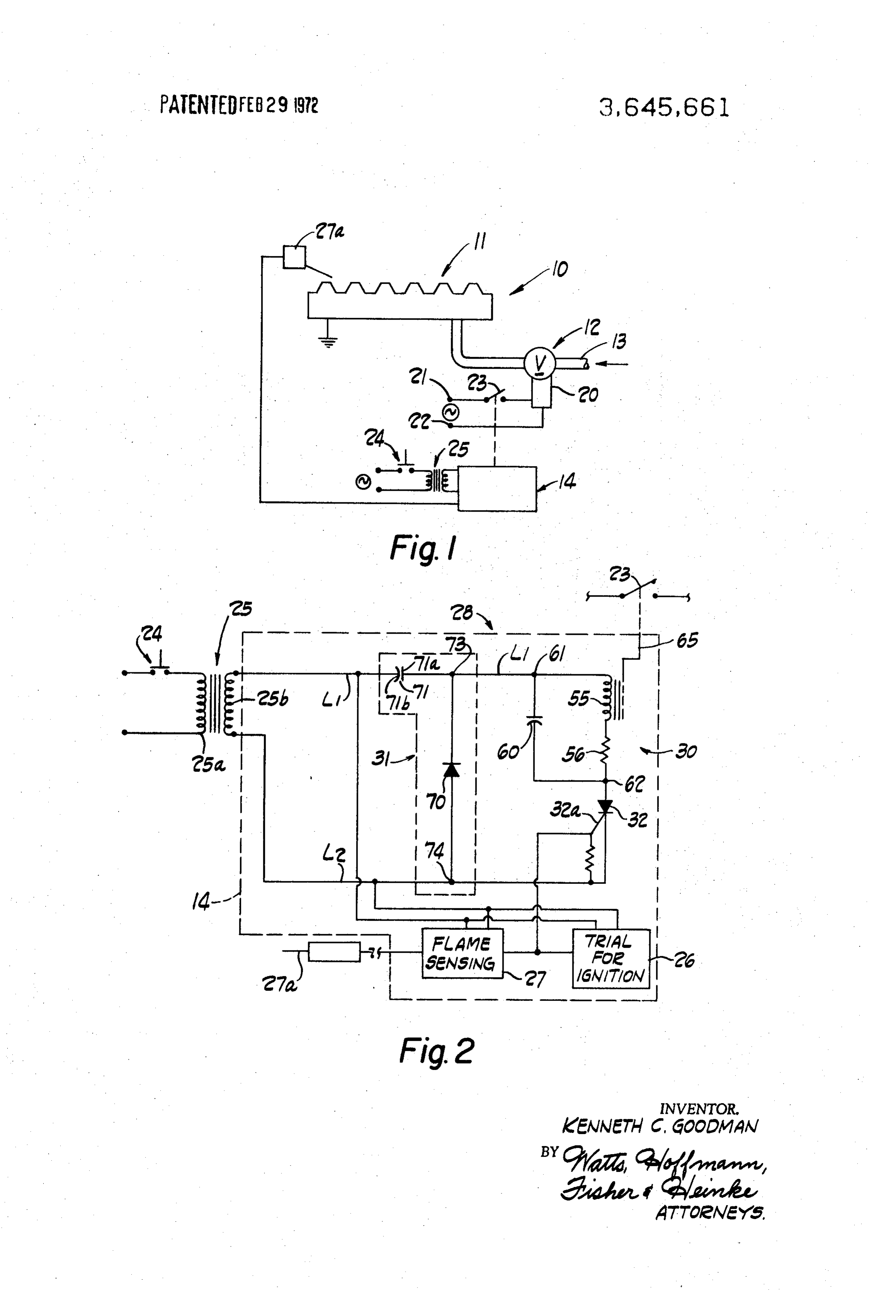
FIG. 2 the present invention; and, is a circuit diagram of a portion of the system of FIG.
relatively expensive which has limited wide commercial ac 75 .
ceptance.
Page 4scan →
DESCRIPTION OF A PREFERRED EMBODIMENT For the purposes of this description, the flame-sensing unit Referring now to FIG. 1, a burner control system 10 is illus 27 is illustrated as utilizing the rectifying effect of a flame to electrical current. This unit produces 60 cycle pulses in trated which includes a burner 11; a fuel supply system 12 for response to the presence of flame between a flame-detecting the burner including a gasline 13 and fuel valve V for opening 5 electrode 27a and the electrically grounded burner 11. If and closing the line 13; and control circuitry 14 governing flame is not established during the trial for ignition period, the operation of the fuel supply system 12. pulses produced by the trial for ignition circuitry terminate The fuel supply system 12 includes a solenoid coil 20 for and the flame sensing unit fails to produce pulses. The SCR is operating the valve V from its closed position to its open posi accordingly prevented from further conduction and the relay tion. The valve V is normally closed and is opened only when 10 circuit is deenergized, closing the fuel valve. When flame is the solenoid is energized. The solenoid 20 is connected across terminals 21, 22 of a suitable electrical power source through sensing unit during established continues the trial for ignition period, the flame to produce pulses after the period and a control switch 23. When the switch 23 is closed, the solenoid the SCR maintains the relay circuit conductive during nega 20 is energized to open the valve V. When the switch 23 is tive half cycles so that the fuel valve is opened. open, the solenoid 20 is deemergized closing the valve V. The 15 The relay circuit 30 includes a relay coil 55 and a resistor 5 control circuitry 14 controls the operation of the switch 23. connected in series with the coil 55. A capacitor 60 is con The circuitry. 14 is connected to the alternating current nected in parallel with the relay coil 55 and the resistor 56 power source through a control switch 24, which is preferably between junctions 61, 62.
thermostatically operated, and a power supply 25. When the The relay coil 55 cooperates with an armature 65 which is switch 24 is closed, the circuitry 14 normally functions to 20 linked close the switch 23 thus opening the fuel valve. When the gized toto"pull the switch 23. When the coil 55 is operatively ener in' the armature 65, the switch 23 closes, thus switch 24 is open, the circuitry 4 closes the fuel valve. opening the fuel valve. In order to "pull in' the armature 65 Referring now to FIG. 2, the power supply 25 is shown as a conventional stepdown transformer having a primary winding 25 the coil 55 must be provided with a predetermined minimum applied voltage. When this predetermined voltage is applied 25a connected across an alternating current single phase across power source through the switch 24, and a secondary winding the gasthe coil, it is operatively energized to effect opening of valve. If, on the other hand, current flows through the 25b having end taps connected to conductors or lines L1, L2, coil 55 but respectively. The conductor L2 is grounded. For the purposes voltage, thethe applied voltage is less than the predetermined of this description, half cycles of the power supply during 3O energized; that is toeven relay, say, though conducting, is not operatively the armature 65 cannot be pulled in.
which the voltage level at the conductor L2 is positive with The coil 55 is bistable in that once the coil is operatively respect to the conductor L1 are referred to as positive half cy energized to pull in the armature, cles. Half cycles of the power supply producing opposite in even though the voltage appliedtheacross armature remains pulled the coil diminishes polarities of the conductors are referred to as negative half cy below the predetermined level. The resistor 56 has an im cles. 35
The circuitry 14 includes a trial for ignition circuit 26, a pedance which is selected so that the relay coil 55 can only be flame sensing circuit 27, and a fuel valve operating circuit 28 operatively energized by a voltage applied across the junctions is substantially greater than the peak power
(FIG. 2). These circuits are all connected across the conduc supply voltage; i.e., the peak voltage across the end taps of the tors L1, L2 for energization from the secondary winding 25b. secondary winding 25b. In other words, the coil 55 is only When the switch 24 closes, the valve operating circuit 28 40 operatively energized in response to application of a predeter opens the fuel valve for a "trial for ignition' period. The ex mined voltage across it which is greater than the maximum tent of this trial period is controlled by the trial for ignition cir cuitry 26. During the trial period, the fuel valve is opened to power supply voltage which can be applied to it. When the voltage applied across the coil 55 and resistor 56 enable a flame to be established at the burner.
If the fuel ignites, the flame-sensing circuit 27 conditions 45 less than is this predetermined voltage, the coil 55, even the circuitry 28 to maintain the fuel valve open so long as though conducting, is not operatively energized and the fuel valve cannot open.
flame is present at the burner. When the flame is extinguished, or the control switch 24 opens, or the circuitry 28 malfunc theThe capacitor 60 is a "flywheel' capacitor which maintains coil operatively energized during positive half cycles of the tions, the fuel valve closes to terminate fuel flow to the burner. 50 power supply. The capacitor 60 is charged when the relay coil The valve operating circuitry 28 (FIG. 2) includes a relay is operatively energized through the SCR during negative half circuit 30 connected across a voltage doubler 31 through an cycles. During positive half cycles the capacitor discharges electronic switch 32.
The electronic switch 32 is preferably an SCr which is con through the coil to provide a sustaining current to maintain nected between the relay circuit 30 and the conductor L2. 55 The the armature pulled in.
The SCR is poled to block conduction through the relay cir voltage doubler 31 developes voltages which are effec cuit 30 from the conductor L2 to the conductor Li during tive to operatively energize the relay coil 55 through the SCR positive half cycles of the power supply. The SCR includes a 32. The voltage doubler 3 includes a diode 70 and a capaci gate electrode 32a which is connected in a circuit with the tor 71 which are connected to produce voltages having peak trial for ignition circuit 26 and with the flame-sensing circuit 60 power supplyofduring amplitudes about twice the peak voltage amplitudes of the negative half cycles. The diode 70 is con 27. The trial for ignition and the flame-sensing circuits may be of any suitable construction and are not illustrated in detail; an nected across the conductors Li, L2 between junctions 73, example of such circuitry is shown in the aforementioned 74, and is poled to block current flow between the junctions copending application, Ser. No. 780,650. during positive half cycles. The capacitor 71 is connected in The flame-sensing unit 27 and the trial for ignition circuitry 65 the conductor Li between the junction 73 and the secondary both function to produce 60 cycle pulses during negative half 25b. During positive half cycles the capacitor 71 charges cycles of the power supply 25, under conditions described through the diode so that at the end of each positive half cycle presently. When either of these units produce pulses, the pull the plate 71a is positive with respect to the plate 71b by an ses are transmitted to the gate electrode of the SCR. The SCR amount substantially equal to the peak voltage of the power is then rendered conductive to complete a circuit through the 70 supply. During the succeeding negative half cycle the voltage relay circuit 30 for opening the fuel valve. level at the plate 71b rises and since the charge across a The trial for ignition circuitry 26 produces 60 cycle pulses capacitor cannot change instantaneously, the voltage level for a limited period after the switch 24 closes. The unit 26thus from the plate 7 a to the conductor L2 increases accordingly, provides a limited period of time during which a flame may be This level rises to about twice the peak voltage of the power established at the burner 1. - 75 supply.
Page 5scan →
The doubled voltage output of the doubler 31 is applied thereacross which is greater than the maximum peak volt across the relay circuit 30 through the SCR.32. Hence, when age which can be applied thereacross directly from said the SCR is rendered conductive during negative half cycles, power supply;
the voltage applied to the coil 55 is more than sufficient to d, an electronic switch means connected in a series circuit operatively energize the coil. The capacitor 60 connected in with said element for completing and interrupting a cir parallel with the coil 55 and resistor 56 is charged to about the cuit through said element in response to a detected condi doubled voltage level since the voltage drop across the SCR is tion; and, minimal. Hence, the capacitor 60 provides the predetermined e. a voltage increasing circuit connected to said power voltage to the coil 55 as the capacitor discharges during posi O supply and having an output connected across said ele tive half cycles and the armature remains pulled in. ment and said electronic switch means, said voltage in creasing circuit effective to produce an output voltage
FALSAFE OPERATION across said element which is in excess of the predeter From the foregoing, it is apparent that the relay coil 55 is mined voltage;
operatively energizable to open the fuel valve only when the 15 f, said electronic means properly operating to complete a SCR 32 is conductive and then only when a predetermined circuit across said output of said voltage increasing circuit voltage, which is substantially greater than the peak voltage of through said voltage responsive element only during first the power supply, is applied across the relay circuit 30. alternate half cycles of said power supply in response to If any component of the circuitry 28 fails, the fuel valve can said detected condition and blocking conduction during not be opened and hence the circuit is failsafe. This is true 20 all second alternate power supply half cycles and during even though the relay coil 55 might be conductive and the first alternate power supply half cycles when said condi peak power supply voltage applied across the relay circuit 30. tion is not detected; and, if either the capacitor 71 or the diode 70 fails, the voltage g. means connected to said voltage increasing circuit and said electronic switch means for rendering said voltage in doubler will not function and the relay coil 55 cannot be pro 25 creasing circuit ineffective to produce said predeter vided with an adequately high voltage to effect opening of the mined voltage when said electronic switch means is im fuel valve. If the plates of the capacitor 71 are short circuited, properly conductive during second alternate power that capacitor cannot be charged and the predetermined volt supply half cycles whereby said voltage responsive ele age will not be developed. If the capacitor 71 fails to open the ment is immediately operated to and maintained in said conductor L1, the relay coil is disconnected from the power 30 first condition regardless of detection of said condition. supply. Shorting of the diode 70 causes the both half cycles of 2. A system as claimed in claim and further including the power supply current to appear across the capacitor 71 means for detecting combustion at said burner, said detecting and prevents the doubler 31 from generating the requisite means effective to operate said switch to complete said circuit doubled voltage for operatively energizing the relay coil. If the through said element.
diode 70 fails open, the capacitor 71 cannot be charged. 35 3. In combustion apparatus including burner control cir If the plates of the capacitor 60 are short circuited, the cuitry for opening a normally closed fuel valve in response to capacitor 60 can no longer function as a "flywheel' for the combustion at said burner, said circuitry comprising: relay coil and the valve V will not open. The shorted capacitor a. an electrical power supply;
also starves the coil 55 for current during negative half cycles. b. a valve operating circuit comprising an operating element If the capacitor 60 fails open, its flywheeling function cannot 40 for effecting opening of said valve, said valve operating be performed. circuit effecting opening of said valve only in response to If the SCR.32 is shorted, it will no longer block current flow a predetermined applied voltage across said valve operat during positive half cycles. This charges the capacitor 60 to ing circuit which is of greater magnitude than the max oppose operation of the voltage doubler and the predeter imum voltage which can be applied thereacross directly mined voltage is not applied across the relay coil 55 during 45 from said power supply;
negative half cycles. If the SCR is open, the coil 55 is discon c. circuit means connected to said power supply and having nected from the power supply. an output connected to said valve operating circuit for The resistor 56 will only fail so as to open the circuit applying at least said predetermined voltage across said through the coil 55, and such failure precludes opening of the 50 valve operating circuit;
fuel valve. d. combustion responsive switching means connected in se While the relay circuit 30 is illustrated and described as in ries with said element, said switching means rendered cluding a relay coil 55, it should be apparent that the disclosed conductive in response to detection of combustion relay circuitry could be modified to provide a valve operating whereby said valve is maintained open by operation of solenoid coil in place of the relay coil 55. said valve operating circuit, said switching means remain Although only a single embodiment of the invention has 55 ing nonconductive at all other times during proper opera been illustrated and described in considerable detail, it will be tion thereof; and, appreciated that various modifications, adaptations and uses e. means cooperating with said switching means and said of this invention will become apparent to those skilled in this circuit means for disabling said circuit means from art and it is the intention to cover hereby all such modifica 60 providing said predetermined voltage when said switching tions, adaptations and uses. means is improperly conductive whereby said operating What is claimed is: element is immediately rendered ineffective to open said 1. In a burner control system having a burner, and fuel valve even though said valve operating circuit is conduc supply means for controlling the supply of fuel to said burner, tive.
electrical circuitry controlling the fuel supply means compris 65 4. A system as claimed in claim3 wherein said power supply produces alternating current and said circuit means comprises an alternating current electrical power supply; a voltage doubler connected to said power supply and effec b. a fuel supply controlling circuit comprising a voltage tive to provide said predetermined voltage to said element. responsive element for effecting operation of said fuel 5. In a burner control system having a burner, and fuel supply means and having a first condition in which the 70 supply means operable to permit and prevent the supply of fuel supply means prevents the supply of fuel to said fuel to said burner, circuitry for controlling operation of said burner and a second condition wherein said fuel supply fuel supply means comprising:
means enables the supply of fuel to said burner; a. an electric power supply;
c. said element operable to said second condition only in 75 b. a voltage responsive coil element having a first condition response to application of a predetermined voltage in which said fuel supply means prevents the supply of 6 fuel to said burner and a second condition for enabling said power supply and blocking current to said element said fuel supply means to permit fuel flow to said burner; during second alternate half cycles when properly operat c. said voltage-responsive coil element operated to said ing;
second condition only in response to a predetermined ap e. a voltage increasing circuit connected to said power plied voltage greater than the power supply voltage; 5 supply and across said fuel supply controlling circuit and d. circuit means for applying said predetermined voltage to said switch means, said voltage increasing circuit effec said coil element in response to a sensed condition, said tive to produce an output voltage across said fuel supply circuit means comprising an electronic switch connected controlling circuit which is in excess of the predetermined between said power supply and said coil for blocking cur- voltage; and, rent flow in one direction and rendered conductive to 10 f. means connecting said switch means and said voltage in enable current flow in said coil in an opposite direction; creasing circuit for disabling said voltage increasing cir and, cuit when said switch means is improperly conductive e. a capacitor connected in parallel with said coil said during second alternate power supply half cycles, said capacitor charging when said switch is conductive and 15 voltage increasing circuit thereby rendered ineffective to discharging when said switch blocks current flow to said produce said predetermined voltage to prevent fuel element. supply to the burner so long as said switch means is im 6. In a burner control system having a burner, and fuel properly conductive.
supply means for controlling the supply of fuel to said burner, 8. In a burner control system having a burner, and fuel electrical circuitry controlling the fuel supply means compris 20 supply means for controlling the supply of fuel to said burner, ing: electrical circuitry controlling the fuel supply means compris a. an alternating current electrical power supply; ing:
b. a fuel supply controlling circuit comprising a voltage a. an alternating current electrical power supply; responsive element for effecting operation of said fuel b. a fuel supply controlling circuit comprising a voltage supply means and having a first condition in which the 25 responsive element for effecting operation of said fuel fuel supply means prevents the supply of fuel to said supply means and having a first condition in which the burner and a second condition wherein said fuel supply fuel supply means prevents the supply of fuel to said means enables the supply of fuel to said burner; burner and a second condition wherein said fuel supply c. said element operable to said second condition only in means enables the supply of fuel to said burner; response to a predetermined voltage thereacross which is 30 c. said element operable to said second condition only in greater than the maximum voltage which could be ap- response to a predetermined voltage thereacross which is plied thereacross directly from said power supply, said greater than the maximum voltage which can be applied voltage-responsive element being, at all other times, in thereacross directly from said power supply; said first condition wherein said fuel supply means d. an electronic switch means having a control electrode, prevents supply of fuel to said burner; 35 said electronic switch capable of conduction only during d. an electronic switch means connected in a circuit with first alternate half cycles of said power supply and said element for completing and interrupting a circuit blocking conduction during second alternate power through said element, said switch means capable of con- supply half cycles;
duction only during first, alternate half cycles of said e. a voltage doubling circuit connected to said power supply power supply when operating properly; 40 and across said fuel supply controlling circuit and said c. a voltage increasing circuit connected to said power switch means, said doubling circuit effective to produce supply and across said element and said switch means, an output voltage across said element which is in excess and voltage increasing circuit effective to produce an out- of the predetermined voltage;
put voltage across said element which is in excess of the f. combustion responsive circuitry for providing signals to predetermined voltage; 45 said control electrode for rendering said switch conduc f. combustion detecting means at said burner, said detecting tive during said first alternate half cycles, said combustion means effective to operate said switch means to complete responsive circuitry effective to provide said signals only said circuit through said element; and, in response to combustion at said burner; and, g. means cooperating with said switch means and said volt- so g. means cooperating with said electronic switch for age increasing means for rendering said voltage increas- preventing said voltage doubler circuit from producing ing means ineffective to provide said predetermined volt- said predetermined voltage when said electronic switch is age across said element when said switch means is im- improperly conductive during second alternate power properly conductive during second alternate power supply half cycles, said voltage responsive element supply half cycles. 55 thereupon being operated to its first condition so that fuel 7. In a burner control system having a burner, and fuel supply to said burner is prevented. supply means for controlling the supply of fuel to said burner, 9. In a burner control system having a burner, and fuel electrical circuitry controlling the fuel supply means compris supply means for controlling the supply of fuel to said burner, ing: electrical circuitry controlling the fuel supply means compris a. an alternating current electrical power supply; 60 ing:
b. a fuel supply controlling circuit comprising a voltage a. an alternating current electrical power supply; responsive element for effecting operation of said fuel b. a fuel supply controlling circuit including a voltage supply means and having a first condition in which the responsive coil for effecting operation of said fuel supply fuel supply means prevents the supply of fuel to said means and having a first condition in which the fuel burner and a second condition wherein said fuel supply 65 supply means prevents the supply of fuel to said burner means enables the supply of fuel to said burner; and a second condition wherein said fuel supply means c. said element operable to said second condition only in enables the supply of fuel to said burner; response to a predetermined voltage applied across said c. said coil operable to said second condition only in fuel supply controlling circuit which is greater than the response to a predetermined voltage thereacross which is maximum voltage which can be applied thereacross 70 greater than the maximum voltage which can be applied directly from said power supply; thereacross by said power supply; d. an electronic switch means connected in a circuit with d. an electronic switch means connected in a circuit with said element for completing and interrupting a circuit said coil for completing and interrupting a circuit through through said element, said switch means being capable of said coil, said switch means completing said circuit during completing said circuit during first alternate half cycles of 75 first alternate half cycles of said power supply and
Page 7scan →
9 , () blocking current to said coil during second alternate half connected in parallel with said voltage-responsive element. cycles. 11. The system claimed in claim 10 wherein said voltage in e. a voltage doubling circuit connected to said power supply creasing circuit comprises a voltage doubling circuit including and across said coil and said switch means, said doubling a capacitor connected in series with said fuel supply con circuit effective to produce an output yoltage across said 5 supply coil which is in excess of the predetermined voltage; and, trollingcontrolling circuit and circuit, a diode said connected in parallel with said fuel doubler effective to provide a f. a capacitor connected in parallel with said coil, said pulsating DC voltage to said fuel supply controlling circuit capacitor charging to at least said predetermined voltage which is greater than the peak power supply voltage. through said switch means when said coil is in the second 12. The system claimed in claim 10 wherein said voltage condition and discharging through said coil during said 10 responsive element comprises a coil and said fuel controlling second alternate half cycles of said power supply to main circuit further comprises a resistor connected in series with tain said coil in said second condition when said switch means blocks conduction. said coil to control the voltage drop across said coil when said electronic switch means conducts.
10. The system claimed in claim 1 wherein said means for rendering said voltage increasing circuit comprises a capacitor 15 :k
Provenance
- Collection
- Patents citing this work
- Pages
- 7
- Method
- pdftotext (the PDF's own text layer) + pdftoppm 300dpi page scans
- Patent office record
- patents.google.com →
- Source
- Google Patents citing-documents table
- Assignee
- Ranco Inc
- Published
- 1972-02-29
- Transcribed from
- patentimages.storage.googleapis.com →