

patent · US3689194A
Direct burner ignition system
5 September 1972
Text
Page 1bibliographic recordscan →
Das et al.
DRECT BURNER IGNITION SYSTEM
72 Inventors: Nalini R. Das, Bethlehem; Edwin H. Strain, Allentown, both of Pa.
Assignee: Caloric Corporation, Topton, Pa.
Int. Cl.................................................F23n 5/10
UNITED STATES PATENTS
3,495,925 2/1970 Willson....................431/80 X
Primary Examiner-Edward G. Favors
Attorney-Harold A. Murphy and Joseph D. Pannone
An ignition system for burners, such as gas- or oil fueled, which includes a novel switch device, an igni tor, a magnetic relay, and a thermocouple, with circuit means being provided which assures fail safe opera tion or discontinuance of the system in the event of malfunction of any one of various components of the system, thereby preventing possibly dangerous accu mulation of fuel without proper ignition. 9 Claims, 2 Drawing Figures
FUEL
SUPPLY
Drawings
Page 2drawing sheetscan →
Page 3scan →
DIRECT BURNERIGNITIONSYSTEM remain open and the circuit to open the valve will not BACKGROUND OF THE INVENTION be completed.
Therefore, undesired and possibly dangerous outflow
Many different types of systems have been developed of unignited fuel is prevented in the system embodying for igniting a fuel for burning in devices such as this invention.
domestic, commercial or industrial appliances, jet en BRIEF DESCRIPTION OF THE DRAWINGS gines, etc. Most common has been the constant burning pilot system where fuel is constantly supplied to a small The foregoing and other objectives have been pilot burner located adjacent a burner to be ignited, 10 achieved by the present invention as illustrated in the and valve means which is manually operated to supply accompanying drawings, wherein:
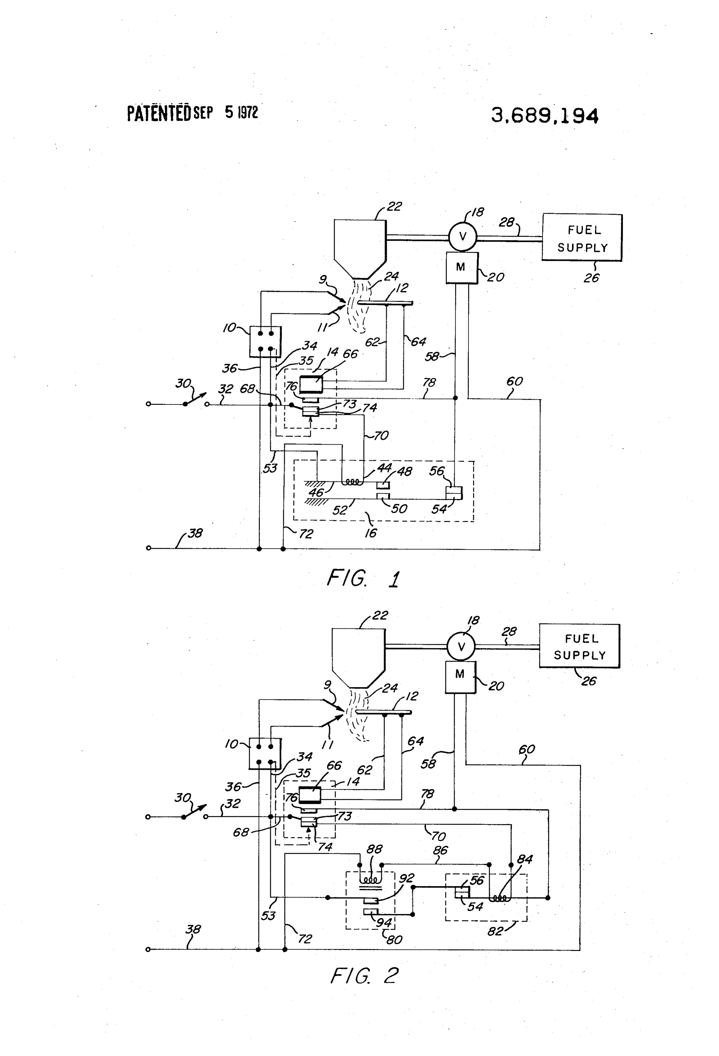
fuel to the burner whereupon it becomes ignited by the FIG. 1 is a schematic diagram illustrating one form of pilot flame. However, such pilot flame often becomes the invention; and extinguished by draft, or by contaminated air. This type FIG. 2 is a schematic diagram similar to FIG. 1 a of failure is well known, for example, in connection 5 modification of the invention.
with broil burners in single cavity ovens or power bur ners in restricted combustion chambers.
Electronic ignitions have been built but have been relatively unsuccessful because of their use of many DESCRIPTION OF THE PREFERRED electronic components with complex inherent failure 20 EMBODIMENT modes. In particular such systems require many elec The novel direct burner ignition system with safety tronic components for flame detection by flame rectifi shut-off according to this invention utilizes as ignitor 10 cation. Needless to say, an electronic system employing to ignite a fuel such as gas, for example, and a ther a spark ignitor for igniting a fuel when a fuel supply valve is opened, for example, is not sufficient without 25 mocouple magnetic 12 combined with a single pole double throw relay 14 for flame detection. A key com safeguards such as means for detecting ignition and for ponent in this system may be a fail safe safety switch 16 closing the valve should ignition not occur because of (FIG. 1) to be described which operates to turn on a failure of the sparking device, or the like. gas valve 18 by means of a motor 20 for a trial ignition Accordingly, an economical and dependable direct period and provides added safety burner ignition system with complete fail safe opera 30 modes, as will be apparent as this indescription the different failure proceeds.
tion has long been sought as a solution to the problems The novel switch 16 is fully disclosed in copending U. of prior art direct ignition systems.
S. patent application Ser. No. 98,496, filed Dec. 16,
SUMMARY OF THE INVENTION 1970 by the present inventors.
The above and other objectives are achieved by the 35 Instead aofnormally the switch 16, however, there could be present invention wherein there is provided a direct aemployed conventional open magnetic relay coupled with normally closed time delay relay which burner ignition system having fail-safe features. Ac will be described more fully in connection with the em cording to this invention the system includes a thermo bodiment of FIG. 2.
stat which operates to complete a first electrical circuit to a spark ignitor and simultaneously completes a 40 Referring more explicitly to FIG. 1, there is shown, second circuit through a single pole double throw mag as one example of utilization of the invention, a gas burner 22 which may be of any suitable type which netic relay to the heater coil of a novel fail safe switch. produces
After a relatively short predetermined time interval the nited in air.a flame 24 when gas from a supply 26 is ig Valve 18 controls the flow of gas from the switch closes through a first set of contacts to complete 45 supply 26 to burner 22 through piping 28. a third
The electrical
Referring to FIG. 2, it will be noted that the switch when closed completes circuit includes a thermostat 30 which 16 of FIG. 1 has been replaced by a normally open an electrical circuit to the igni magnetic relay 80 and a conventional normally closed tor 10 through wires 32, 34, 36 and 38. The ignitor 10 time delay relay 82. In this embodiment closing of ther 50 may be any suitable device such as a sparking device mostat 30 completes a circuit through wires 32 and 68, wherein sparks are produced across a gap when the contacts 73 and 74, wire 70, heater coil 84 of relay 82, deviceignitionis energized, or a hot wire device which reaches wire 86, coil 88 of relay 80, and wires 72 and 38. This fuel through it.
temperatures when current is passed in turn closes the contacts 92-94 in relay 80 and starts the timing cycle in the normally closed time delay relay 55 Closing of the thermostat 30 also completes a circuit 82. When the contacts 92-94 close, they complete the to the heater coil 44 of the safety switch 16 through circuit to motor 20. This energizes the valve 18, allow wires 32 and 68, normally closed contacts 73-74 of the ing gas to magnetic relay 14, and wires 70, 72, and 38. The coil In accordance with this invention the system em 44 is located in adjacent or surrounding relation to a bodies fail-safe features whereby the valve will be bimetallic strip 46 carrying a first contact 48 of a pair closed to shut off the supply of fuel in the event the 60 of normally open contact, the other 50 of said contacts thermocouple or the magnetic relay fails to operate, in being fixed to a flexible conductive strip of blade 52. which case the novel switch will open the circuit When the coil 44 is energized for a predetermined time through the second set of contacts to close the valve. In interval the bimetallic element will respond by flexing the event the ignitor fails to operate, the novel fail safe 65 in the well-known manner so that contacts 48-50 will switch will again operate to open the circuit through its close. This completes a circuit to motor 20 through second set of contacts to close the valve. Also, if the wires 32 and 53, strip 46, contacts 48–50, blade 52, heater coil of the switch fails to operate, the switch will normally closed contacts 54–56, and wires 58 and 60.
Page 4scan →
Energizing of motor 20 will cause valve 18 to open, al Time cycles are adjustable through variations in struc lowing gas to flow into the burner 22. ture of the bimetallic element in the safety switch and The electrode pair 9, 11 is located relatively close to in the positions of the junctions in the thermocouple. the burner outlet so that when the gas flows out from It is to be understood that various changes may be the burner 22 the sparks which are being produced by made by those skilled in the art without departing from the energized ignitor 10 will cause the desired gas igni the spirit of the accompanying claims. tion to produce flame 24. We claim:
The thermocouple 12 is positioned so as to be heated 1. A direct burner ignition system comprising electri by the resultant flame and thus generates a voltage 10 cally operable valve means for controlling flow of fuel which passes current through wires 62-64 to the coil 66 to a burner, ignition means for igniting fuel at the of relay 14. The energized coil 66 causes contacts burner and producing a resultant flame therefrom, and 73-74 to open and contacts 73-76 to close. This means for controlling the valve means in response to establishes a second circuit to the motor 20 through detection or non-detection of said flame, said last wires 32 and 68, contacts 73-76, wires 78 and 58, and 15 means comprising a thermocouple located within said wires 60 and 38. This allows the valve 18 to remain flame when the flame exists, a safety switch connected open. At the same time, opening of contacts 73-74 cuts to said valve means and including a heating element, a off power to the coil 44 of switch 16, allowing the con relay connected to a source of electrical energy in se tacts 48-50 to again open. The ignitor 10 is allowed to ries with said heater element, the thermocouple being continue functioning during the entire time that the connected to said relay to operate the relay to break thermostat 30 is closed and the valve 18 open as a the circuit to said heater element in response to detec safety measure. However, the ignitor may, if desired, be tion of said flame, and said switch being operable to connected so as to be interrupted after the flame has shut off said valve means in the event the thermocouple been established. This is accomplished by removing does not detect a flame and consequently does not wire 34 and by adding wire 35 from ignitor 10 to con 25 operate the relay, tact 74 in relay 14, as shown by the dotted line in FIG. 2. A direct burner ignition system comprising electri 1. cally operable valve means for controlling fuel flow to a When the thermostat 30 opens, this opens the circuit burner, ignition means for igniting fuel at the burner to to all the components and allows them to return to their produce a flame, thermostat means connected to said normal conditions. The motor 20 is of the type which, 30 ignition means for energizing and deenergizing the igni when power is removed, will automatically close the tion means, flame detecting means for developing cur valve 18 and thus cut off the flow of gas to the burner. rent when flame is detected, and safety means for Two well-known types of such motor and valve com deenergizing the valve means after a predetermined binations are a solenoid, and an electric valve using a 35. time period when no flame is detected, said safety bimetal strip and heater. means comprising a relay and a switch in series It will be apparent that the described system has between the ignition means and the valve means, said many desirable safety features. For example, if the relay having a pair of normally closed contacts, and thermocouple 12 or the magnetic relay 14 fails to func said switch having a heater element connected to said tion, the safety switch 16 would operate to prevent 40 relay contacts.
damage or destruction. To achieve this, since the relay 3. A direct burner ignition system as set forth in will not function to open contacts 73-74, the heater claim 2 wherein said switch includes bimetallic means coil 44 will continue to heat the bimetallic element 46, operable by heat from said heater element, a second causing continued bending of the element which will, pair of normally open contacts adapted to be closed through pressure on blade 52 by the closed contacts 45 upon operation of said bimetallic element, and means 48-50, cause the blade 52 to bend and thereby open for completing a circuit through said second pair of the normally closed contacts 54-56. This will deener contacts when closed to the valve means. gize the motor 20 and close the valve 18. 4. A direct burner ignition system as set forth in Should the ignitor 10 fail, the safety switch 16 will claim 2 wherein said switch includes bimetallic means again function as described in the preceding paragraph 50 operable by heat from said heater element, a first pair to close the valve 18. of normally open contacts adapted to be closed upon Should the heater coil 44 fail, switch contacts 48-50 operation of said bimetallic means, and a second nor will remain open whereupon the motor 20 will not be mally closed pair of contacts, completing a circuit to energized to open valve 18. flow to burner 22. said valve means.
It will be apparent that should the coils 43 or 45 fail, 55 5. A direct burner ignition system as set forth in contacts 92-94 will remain open, whereupon the motor claim 4 wherein said relay includes switch means 20 will not be energized to open valve 18. operable in response to said flame detecting means for From the foregoing it will be apparent that all of the opening the circuit to the switch heater element and for objectives of this invention have been achieved by the 60 completing energization of the valve means through novel fail safe system described. It will also be apparent another circuit.
that the described system may be used for many types 6. A direct burner ignition system as set forth in of fuel-fired burners other than the burner disclosed. claim 4 wherein said bimetallic means comprises a Furthermore, the present system has many other ad movable member for initially closing said first pair of vantages over the prior art electronic and pilot type ig 65 contacts when the heater element is operated and for nition systems. subsequently opening the second pair of contacts at the With the present system ignition has been found to end of a predetermined time interval and for thereby occur as soon as the gas is available at the burner port. causing closure of said valve means.
Page 5scan →
7. A direct burner ignition system as set forth in to a burner, ignition means for igniting fuel at the claim 2 wherein said safety means further comprises a burner and producing a resultant flame therefrom, and pair of second and third relays each including a heating means for controlling the valve means in response to element, the first relay being connected to said flame detection or non-detection of said flame, said last detecting means and having a pair of normally closed 5 means comprising flame sensing means located in prox contacts in a series hookup with the heater elements of imity to said flame when the flame exists, a safety the second and third relays between the ignition means switch connected to said valve means, a relay con and the valve means. nected to a source of electrical energy in series with 8. A direct burner ignition system as set forth in said switch, the flame sensing means being connected claim 7 wherein said first relay includes switch means O to said relay to operate the relay to break the circuit to operable in response to said flame detecting means for said heater element in response to detection of said opening the circuit to the heater elements of the second flame, and said switch being operable to shut off said and third relays and for completing energization of the valve in the event the flame sensing means does not de valve means through another circuit. tect a flame and consequently does not operate the 9. A direct burner ignition system comprising electri relay.
cally operable valve means for controlling flow of fuel air k
Page 6scan →
United states patent office
Certificate of correction
Patent No. 3, 689,194 Dated September 5, 1972 Inventor(s) Nalini R. Das and Edwin H. Strain
It is certified that error appears in the above-identified patent and that said Letters Patent are hereby corrected as shown below: On cover sheet, line 73, change Assignee from "Caloric Corporation Topton, Pa." to -- Raytheon Company Lexington, Ma. -- Column 1, 1ine 45, after "third" insert -- circuit through a second set of contacts to an electric valve which opens to supply fuel to a burner. When the burner is operated, a thermo couple detects the heat from the burner and through operation of the relay establishes another circuit to the valve, keeping it open, and breaking the circuit to the fail safe switch, whereupon the valve will remain open as long as the thermocouple detects heat from the burner, or until the thermostat opens to break the circuit to the valve and to the ignitor. --
Column 1, 1ines 46-57, delete the entire paragraph. Column 2, 1ine 14, after "FIG. 1" insert -- illustrating -- Column 2, line 60, delete 'contact" and insert -- contacts-- Column 3, line 54, after 'valve 18. ' delete 'flow to burner 22. '
Column 5, at line 55, insert the following paragraph: -- Referring to FIG. 2, it will be noted that the switch 16 of FIG. 1 has been replaced by a normally open magnetic relay 80 and a conventional normally closed time delay relay 82. In this embodiment closing of thermost at 30 completes a circuit through wires 32 and 68, contacts 73 and 74, wire 70, heater coil 84 of relay 82, wire 86, coil 88 of relay 80, and wires 72 and 58. This in turn closes the contacts 92-94 in relay 80 and starts the timing cycle in the normally closed time delay relay 82. When the contacts 92-94 close, they complete the circuit to motor 20. This energizes the valve 18, allowing gas to flow to burner 22. - -
Signed and sealed this 1st day of May 1973.
Attest:
E.A.P. i.i. FITCHER, JR. ROBERT GOTTSCHALK Attesting Officer COmmissioner of Patents
FORM po- Oso (10-69) USCOMMs oc 6037 euroeg U.S. Gow ERNMENT PRNTING OFFICE: is o-gss-ss
Provenance
- Collection
- Patents citing this work
- Pages
- 6
- Method
- pdftotext (the PDF's own text layer) + pdftoppm 300dpi page scans
- Patent office record
- patents.google.com →
- Source
- Google Patents citing-documents table
- Assignee
- Caloric Corp
- Published
- 1972-09-05
- Transcribed from
- patentimages.storage.googleapis.com →