

patent · US3838652A
Furnace installation for burning liquid or gaseous fuel, in particular for a boiler
1 October 1974
Text
Page 1bibliographic recordscan →
United States Patent (19)
Schol
54 FURNACE INSTALLATION FOR BURNING
LIQUID OR GASEOUS FUEL, IN
PARTICULAR FOR A BOILER
75 Inventor: Robert Cornelis Schol, Hilversum, Netherlands Assignee: Ingenieursbureau Rodenhuis &
Verloop N.V., Hilversum,
Netherlands
30 Foreign Application Priority Data
Jan. 6, 1972 Netherlands....................... 7200207
51 int. Cl............................................... F235/02
UNITED STATES PATENTS
1,729,763 10/1929 DeFlorez ..................... 4311)|G. 13
2,224,544 2/1940 Keller ............................. 1221479 A 2,701,608 2/1955 Johnson................................ | Of 49 2,993,479 7/1961 Thurley........................ 43 1/DIG. 13
Primary Examiner-John J. Camby
Assistant Examiner-Henry C. Yuen
Attorney, Agent, or Firm-Eric H. Waters
A furnace installation for burning liquid or gaseous fuel with recycling of the flue gases, in particular for a boiler, comprising at least one burner directed through a flame hole in the wall of the combustion chamber of the installation, and a duct member for conducting secondary combustion air to the flame hole, the recycled flue gas being supplied to the flame hole through openings arranged circumferentially in the duct member adjacent the flame hole whereby the flue gas flowing through these openings and through the flame hole into the combustion chamber forms a cooling mantle of flue gas enveloping the flame of the burning fuel emanating from the burner.
8 Claims, 3 Drawing Figures
Drawings
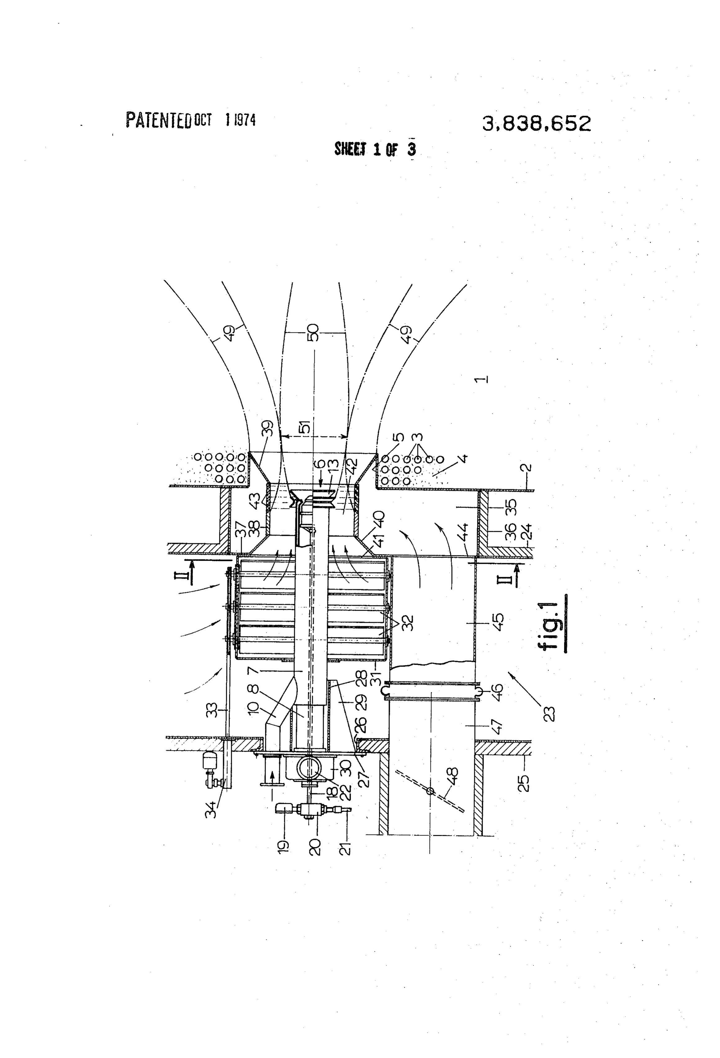
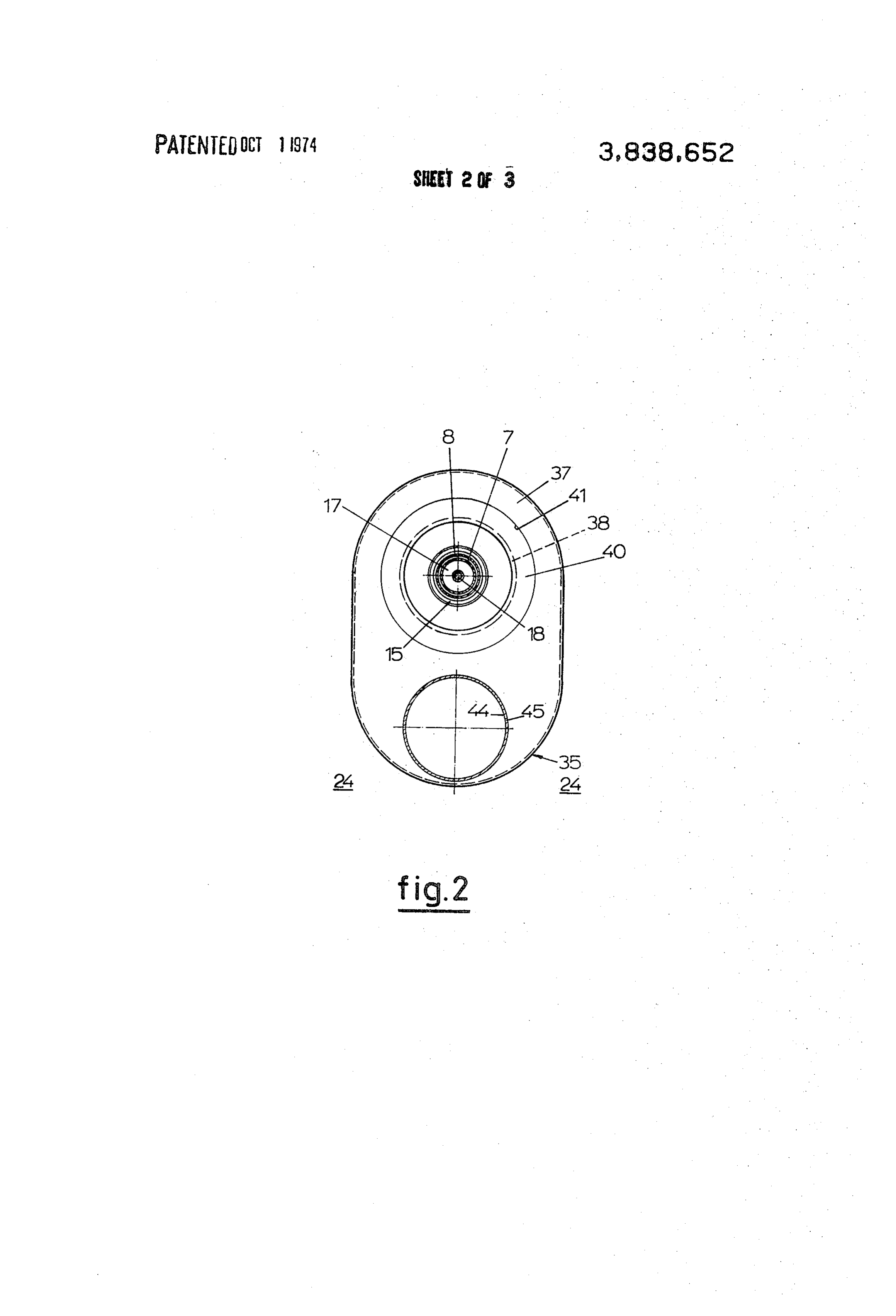
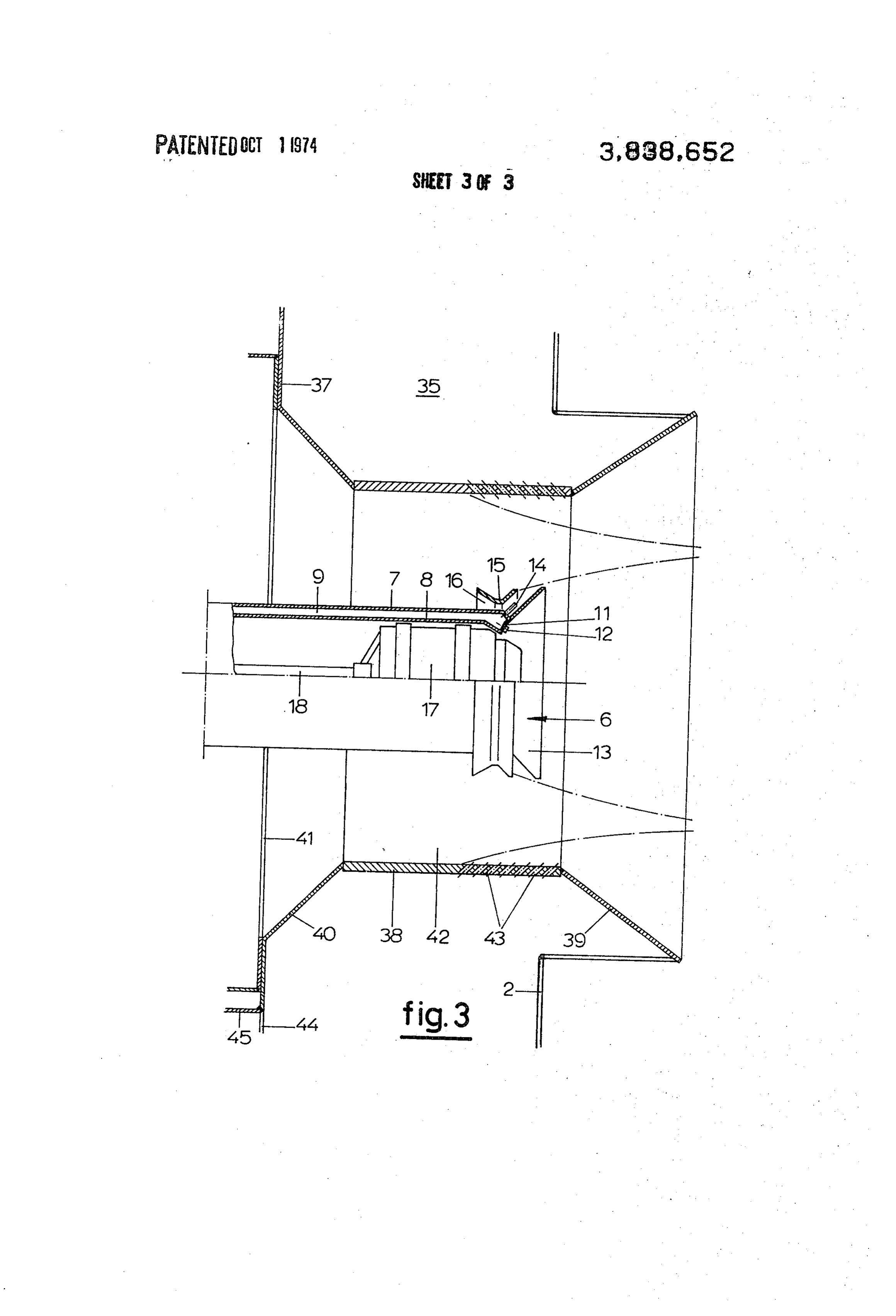
FIG. 2 is a view of the flue gas box of the installation
Page 2drawing sheetscan →
Page 3drawing sheetscan →
Page 4drawing sheetscan →
Page 5scan →
FURNACE INSTALLATION FOR BURNING LIQUID The flame is thus cooled in the desired manner di OR GASEOUS FUEL, IN PARTICULAR FOR A rectly it is formed by means of the flue gas mantle en BOLER veloping it without the necessity of first mixing the flue gases with the combustion air. This way of flame cool
Background of the invention
ing also offers a further considerable advantage in terms of control technique. On the basis of a boiler de
The invention relates to a furnace installation for sign with, for example, 15 percent flue gas feed into the burning liquid or gaseous fuel with recycling of the flue combustion chamber at full load, this proportion is in gases, in particular for boilers. More in particular, the creased as the load falls, so that, as is described above, invention relates to such a furnace installation having O the mass flow through the superheater is kept at a rea a furnace wall enclosing a combustion chamber and sonable value. In the arrangement of the invention, an provided with at least one flame hole, a burner being increase in the amount of flue gas supplied has the ef mounted in line with this flame hole for directing fuel fect of causing the neck of the burner assembly to be-, through the hole to be burned in the combustion cham 15 come seemingly narrower and consequently, when a ber, which flame hole is in communication with a pres smaller amount of combustion air is supplied, the fall sure source for secondary combustion air whereby this in pressure in the neck and thus the speed of the com air flows past the burner and through the flame hole bustion air flowing outwards changes only slightly. This into the combustion chamber while mixing with the means that over a wide range of load adjustment a sub fuel injected by the burner. stantially constant mixing energy per unit of combus tion air volume supplied and thereby optimum mixing
In the operation of such furnace installations high 20 of flame temperatures may occur and it is known that the fuel with the combustion air are obtainable. such high flame temperatures result in the forming of In an installation having a plurality of burners it is oxides of nitrogen which are harmful to the environ preferable to supply the recycled flue gas to each ment. Attempts have therefore been made to reduce 25 trol valve for thisanburner.
burner through individually adjustable flue-gas con the normal temperature for oil and natural gas flames by means of these controlThe advantage of this is that of approximately 1,700-1,800° C to below the border tween the combustion air and thethevalves mixture ratio be line temperature of approximately 1,300° C which is vidually and differently adjusted forflueevery gas can be indi burner. It is critical to the development of such nitrogen oxides. thus possible to have a first burner group work in It is further known to control the flame temperature 30 of such furnace installations by leading an adjustable super-stoichiometric state and to have a second group work in sub-stoichiometric state so that exactly the de part of the consumed flue gases together with the sec sired amount of combustion air enters the combustion ondary combustion air to the burners in dependence on the boiler load in order that, as the load decreases, the chamber for the flames of both burner groups intoto. speed of the gas flowing through the superheater can be 35 mentionedis burner
As there a drop in the flame temperature in both maintained at substantially the same level so as to keep flame as a result of astates, surplus caused by cooling of the of cool combustion air and the performance of the superheater and the tempera as a result of initially incomplete combustion caused by ture of the produced superheated steam as constant as an inadequate amount of air, respectively, possible, It has also been suggested to add a specific flame is thus achieved on all burners withouta loss cooler amount of flue gas to the secondary combustion air at 40 performance.
full load in order to achieve a lower flame temperature.
In the arrangement of this type known thus far the flue BRIEF DESCRIPTION OF THE DRAWINGS gas is conducted directly into the wind box for the com Other objects and advantages of the invention will bustion air. This suffers from the disadvantage, how appear from the following description, in conjunction ever, that this combustion air and the flue gas added to 45 with the accompanying drawings, of a preferred em it generally have different temperatures and therefore bodiment of the furnace installation according to the do not mix well which leads to an irregular flame and invention. In the drawings:
makes it difficult to achieve good control. FIG. 1 is an axial section through one of the burner locations of the installation;
FIG. 2 is a view of the flue gas box of the installation
The invention has for its main object to provide a fur in a section along the line II-II of FIG. 1; and nace installation of the kine above referred to which FIG. 3 is an axial section through the burner head on obviates the above-discussed disadvantage of the an enlarged scale, known arrangements and which allows to keep the flame temperature below the limit which is critical to 55 DESCRIPTION OF OF A PREFERRED EMBODIMENT
The invention
the development of nitrogen oxides while maintaining a stable flame and a good control both at full load and The drawings show one burner location of a boiler at reduced load. fitted, in a known manner, with a plurality of burners. In the furnace installation according to the invention, The boiler has a combustion chamber 1 within a fur the recycled flue gas is supplied to each one of the 60 nace wall 2 on which are mounted boiler tubes 3 and flame holes by conducting means which open circum a boiler wall insulation 4, as is shown diagrammatically ferentially of the flow of secondary combustion air ad in FIG. I. The furnace wall has a number of flame holes jacent the periphery of the flame hole whereby the flue such as 5 each with a similar burner 6 mounted there gas flowing together with this combustion air through 65 behind, only one of which can be seen in the drawings. the flame hole forms a mantle of flue gas enveloping and thereby cooling the flame of the burning fuel in The burner 6 can be of any suitable type for burning jected by the burner. liquid and/or gaseous fuels. The burner illustrated here 6 is of the kind as described in my British Pat. No. nism 34 attached to this wall, so as to control the supply 1,080,528, being a burner for fuel oil as well as for nat of secondary combustion air to the burner in a known ural gas. The burner has a double-walled cylindrical casing with an outer wall 7 and an inner wall 8 which The above-described parts of the furnace installation enclose a ring-shaped gas channel 9 into which natural are as such of known construction and design. gas or another suitable gaseous fuel can be supplied by According to the invention, a flue-gas box 35 is built means of a gas supply conduit 10 which is attached to against the furnace wall 2 of the boiler and around the the rear end of the outer wall 7 and extends rearwards. flame hole 5 in this wall. The box 35 has an approxi Both walls 7 and 8 run conically inwards at the front mately elliptical peripheral shape (FIG. 2) with circum end and meet up with a conical front wall 11 which O ferential side wall 36, extending between the inner wall seals off the space 9 and in which is provided an annu 24 of the wind box 23 and the furnace wall 2, and with lar row of outlet bores 12 for the fuel gas. A cone a back wall 37 which fits into a corresponding aperture shaped flame funnel 13 which extends forward is at in the wall 24 of the wind box. A tubular sleeve 38, co tached to this front wall 11. Immediately behind this axial with the burner, encloses the head of the burner funnel 13 a crown of outlet tubes 14 for the fuel gas are and is housed in the flue-gas box 35, which sleeve has screwed into the in-turned end of the outer wall 7, their a smaller diameter than the flame hole 5 and is con axes lying on a conical surface and running parallel to nected on the one handby a funnel-shaped wall portion the generatrices of the funnel 13. Behind the funnel 13 39 to the inner edge of the flame hole 5 and on the there is an air deflecting bushing 15 attached to the other hand by a funnel-shaped wall portion 40 to the outer wall 7 by means not shown, this bushing widening edge of an aperture 41 in the back wall 37 of the flue conically at its front side to match the shape of the fun gas box, said aperture 41 having approximately the nel 13 and becoming likewise conically wider at the same diameter as the flame hole 5. In this way there is rear. Between the outer wall 7 with the flame funnel 13 formed between the wind box 23 and the flame hole 5 attached thereto and the air deflecting bushing 15 an a throughflow duct or channel for the secondary com annular air channel 16 which has a contracted throat 25 bustion air, which encloses the foremost part of the at the middle, is thus formed, so that mixing air is con burner 6, and has a constriction 42 around the head of ducted, in a way which will be described below, along the burner.
the outflow tubes 14 for the gas. The forward part of the sleeve 38 has a large number An oil burner 17 is fitted into the gas burner casing 30 of outflow apertures 43 for the flue gas which are dis 7, 8 and can again be of any suitable type, but in the ex tributed in series circumferentially of the sleeve and ample shown it is designed in accordance with my run obliquely inwards and forwards as shown in FIG. 3. Dutch Pat. Application 270,257 and provides two stage atomization of the oil by means of primary com A circular aperture 44, in the back wall 37 of the fue bustion air or atomizing air under higher pressure than 35 gas box 35 next to the aperture 41, receives a tube 45 the secondary combustion air. The oil is supplied connected by means of an expansible member 46 to a through an oil feed conduit 18 which runs centrally tubular conduit 47 which extends through the wall 25 through the casing 7, 8 and is attached at its rear end of the wind box 23 and houses...a butterfly valve 48. The to a flexible feed pipe 21 via a coupling member 12 tube 45 and conduit 47 form a flue-gas duct fed by a which is fitted with an oil pressure gauge 19. The atom 40 flue-gas collecting channel (not shown) from which the izing air is led in within the inner casing wall 8 which flue-gas ducts of the various burner locations branch has at its rear end a lateral connecting member 22 for off and to which the part of the boiler flue gas which connecting with a source of compressed air which is to be recycled is supplied by known means. With the supplies air under constant pressure. help of the valve 48 it is thus possible to regulate the The combined gas and oil burner 6 lies with its 45 amount of flue gas supplied to each burner. burner mouth in the centre directly behind the circular When using the burner 6 as a gas burner natural gas flame hole 55 and extends rearwards through a wind is, for instance, supplied to the feed conduit 10, while box 23 which is common to the various burners. This the oil conduit 21 is closed. The secondary combustion wind box 23 lies enclosed between an inner wall 24 and air from the wind box 23 flows around the burner an outer wall 25 and by means of natural draught or by 50 through the constriction 42 into the combustion cham means of a forced draught fan supplies the secondary ber. Part of this air moving along the outer wall 7 of the combustion air. The outer wall 25 of the wind box has burner casing flows through the annular channel 16 an aperture 26 which is sealed off by a burner front within the deflector bushing 15 to provide mixing air plate 27 which is removably attached. This front plate for the gas emerging from the gas outlet tubes 14 27 supports the outer casing wall 7 of the burner by 55 whereupon the resultant air-gas mixture is mixed again means of a bushing 28 and reinforcing plates 29. The with the secondary combustion air flowing through the gas feed conduit 10, the oil feed conduit 18, and the constriction 42 so that the result is a ring-shaped flame. inner casing wall 8 with the connecting member 22 for Gas also enters the space within the flame funnel the atomizing air, extend sealingly through this front through the narrow gas outflow bores 12, and is thor plate 27 and a dome-shaped member 30 attached to it. 60 oughly mixed with the primary air emerging with pro nounced turbulence from the mouth of the coil burner
A rectangular casing 31, through which the burner 6 17, the result being a constant stable fan-shaped flame at the mouth of the burner 17 which serves as a sup extends, is attached to the inner wall 4 of the wind box 23, this casing having pivotable shutter flaps 32 con porting flame for the ring-shaped main flame. If the nected to each other and mounted in two opposite 65 burner 6 is used as an oil burner the gas supply is closed facing casing walls. The flaps 32 are adjustable by and oil is supplied under pressure to the oil feed con means of an operating rod 33, which extends through duit 18. The oil which emerges is atomized in two the wall 25 of the wind box, and an operating mecha stages, in the manner as described in the above men 7 tioned Dutch Pat. Application 270,257, by means of flame hole for directing fuel through said hole to be the emergent atomizing air which has been subjected to burned in said combustion chamber; a source of secon pronounced turbulence, and is then mixed with the sec dary combustion air; duct means for conducting said ondary combustion air flowing through the constriction secondary combustion air to said flame hole; means for 42. In specific cases it is also possible to burn gas and conducting recycled flue gas to said flame hole, said oil simultaneously in the burner 6. r means opening circumferentially into said duct means The pressure of the flue gas in the flue-gas box 35 is adjacent to said flame hole whereby said flue gas flow somewhat higher than that of the air in the wind box ing through said flame hole forms a mantle of flue gas 23. During the operation of the burner, the flue gas enveloping the flame of said burning fuel; a flue gas box which flows through the apertures 43 into the constric O mounted on the outside of said furnace wall around the tion 42 forms a mantle 49 of flue gas whose boundary flame hole, said box having a back wall opposite said lines 49 are shown diagrammatically in FIG. 1 and furnace wall and provided with an aperture in line with which gradually spreads over some distance in the form said flame hole; a flue gas conduit opening into said of a funnel in the combustion chamber 1 from the per box; sleeve means extending through said box and co forated part of the sleeve 38 and the funnel-shaped wall 5 axially enclosing said burner, said sleeve means having portion 39. This mantle 49 of flue gas thus forms an a forward end joining the periphery of said flame hole evelope for the burning air/fuel mixture which emerges from the burner 6, its outline being shown diagrammat and ture having a rear end attached to the edge of the aper in said box rear wall whereby a ring-shaped duct ically by 50. This flame 50 is consequently cooled in its for said secondary combustion air is formed between hottest part by the flue-gas mantle 49 enveloping it 20 said sleeve whereby the flame temperature can be brought below flue gas boxand and said burner and passing through said communicating with said source of the above-mentioned critical boundary temperature of secondary combustion air, said sleeve having outflow
AS can be seen in the drawings, the emerging mantle around its circumference gas apertures for the flue uniformally distributed of flue gas initially bends inwards from the outflow ap 25 2. The installation of claim 1 includinginto and opening said duct.
an adjustable ertures 43 and has its smallest internal diameter (smaller than the diameter of the constriction 42) at flue gas valve mounted in said flue gas conduit. 3. The installation of claim 1, in which said outflow the point indicated by the broken line 51 just in front apertures of the mouth of the flame hole 5. The minimum diame for said flue gas, as seen in the direction of ter of this mantle throat 51 depends upon the amount 30 flow, run obliquely forwards and inwards from said flue of flue gas which is flowing out, and this can be ad gas4.box into said annular duct. justed by means of the valve 48. When the boiler is meansThe installation of claim 2 in which said sleeve under full load, in which case, for instance, 15-20 per diameter than saida flame comprises cylindrical sleeve section of smaller cent flue gas is added relative to the total volume of flue gas box back wall, ahole and said aperture in said first conical sleeve part con out-flowing gas, this minimum diameter will be only 35 necting said cylindrical sleeve section to the periphery. slightly smaller than that of the constriction. 42. With a smaller boiler load appropriate adjustment of the of said flame hole, and a second conical sleeve part valves 32 and 48 makes the proportion of flue gas ture connecting said cylindrical sleeve section to said aper greater, however, whereby the mantle throat 51 be in said flue box back wall. comes smaller. As has already been explained above, 40 5. The installation of claim 4 in which said flue gas the result of this contraction is that the pressure head outflow apertures are in said cylindrical sleeve section for the combustion air which is now flowing out in a adjacent said first conical sleeve part. smaller quantity, and thus also the speed of this air, re 6. The installation of claim 1 further comprising a main approximately the same, which fact greatly con wind box for said secondary combustion air, the burner tributes to the achievement that, also at a smaller load, 45 being housed in said wind box, said wind box joining a proper mixing of fuel and air is maintained. said back wall of said flue gas box and communicating As has already been described, the flue gas control with said aperture in said back wall, and a control valve valves 48 can be individually adjusted for the different means arranged in said wind box controlling the flow burners so that one burner group can work in a of secondary combustion air from said wind box to said superstoichiometric state and one burner group in a 50 aperture.
substoichiometric state, which provides the above 7. The installation of claim 6 wherein said flue gas mentioned favourable additional possibilities for lower conduit passes through said wind box to said flue gas ing the flame temperature. box.
What is claimed is: 8. The installation of claim 1 including a plurality of 1. A furnace installation for burning liquid or gaseous 55 burners, said flue gas conducting means comprising a fuel with recycling of the flue gases, in particular for a flue gas supply conduit for each of said burners and an boiler, comprising a combustion chamber; a furnace individually adjustable flue gas valve in each of said wall enclosing said combustion chamber and having at supply conduits. is k ck least one flame hole; a burner mounted in line with said
Provenance
- Collection
- Patents citing this work
- Pages
- 7
- Method
- pdftotext (the PDF's own text layer) + pdftoppm 300dpi page scans
- Patent office record
- patents.google.com →
- Source
- Google Patents citing-documents table
- Assignee
- Rodenhuis & Verloop Bv
- Published
- 1974-10-01
- Transcribed from
- patentimages.storage.googleapis.com →