

patent · US3852021A
Internal recirculation burner
3 December 1974
Text
Page 1bibliographic recordscan →
United States Patent (19)
Quinn
(54) INTERNAL RECIRCULATION BURNER
Inventor: Ronald E. Quinn, Indianapolis, Ind. Assignee: General Motors Corporation,
Detroit, Mich.
52 U.S. Cl.................................. 431/116, 431/158 (51 int. Cl. ............................................. F23m 9/06
UNITED STATES PATENTS
2,539,165 1/1951 Saha............................... 431 fl 16 2,701,608 2/1955, Johnson.............................. 431/1 16 3,319,692 - 5/1967. Reba et al........................... 43111 16
FOREIGN PATENTS OR APPLICATIONS
1,551,653 1 1/1968 France................................ 431/1 6
Primary Examiner-Edward G. Favors
Attorney, Agent, or Firm-J. C. Evans
An air-fuel combustor having a swirl inducing device at the inlet end thereof for producing premixing of air and fuel in a mixing chamber upstream of a combus tion chamber and to produce a reverse recirculation of combustion gases from a downstream combustion chamber through the mixing chamber. An inner de flector plate forming the combustion chamber has an annular deflector plate forming the combustion cham ber has an annular nozzle supported thereon which is supplied with primary air to produce an attached wall jet flowing across the inner deflector plate of the com bustion chamber to promote recirculation flow there through and to promote reversal of flow of the recir culation pattern at one end of the combustion cham ber to reduce pressure drop through the combustor assembly.
5 Claims, 8 Drawing Figures
Drawings
Page 2drawing sheetscan →
Page 3drawing sheetscan →
Page 4drawing sheetscan →
Page 5drawing sheetscan →
Page 6scan →
NTERNAL RECIRCULATION BURNER pump means for directing primary air with respect to This invention relates to fuel and air combustor as the swirl induced recirculating flow through the com bustion chamber to increase the rate of recirculation so semblies and more particularly to combustors including as to improve the blow out characteristics of the com means therein for promoting recirculation of combus bustor assembly when operating under lean air-fuel tion gases to heat inlet and air-fuel mixtures prior to ratio conditions.
passage thereof into the inlet end of a primary combus Further objects and advantages of the present inven tion zone. tion will be apparent from the following description, Various combustor designs have been proposed and reference being had to the accompanying drawings tested using either swirl or jet induced recirculation for 10 wherein a preferred embodiment of the present inven mixing the heated combustion products with the fresh tion is clearly shown.
fuel-air mixture. Particularly, pumping by an attached In the Drawings:
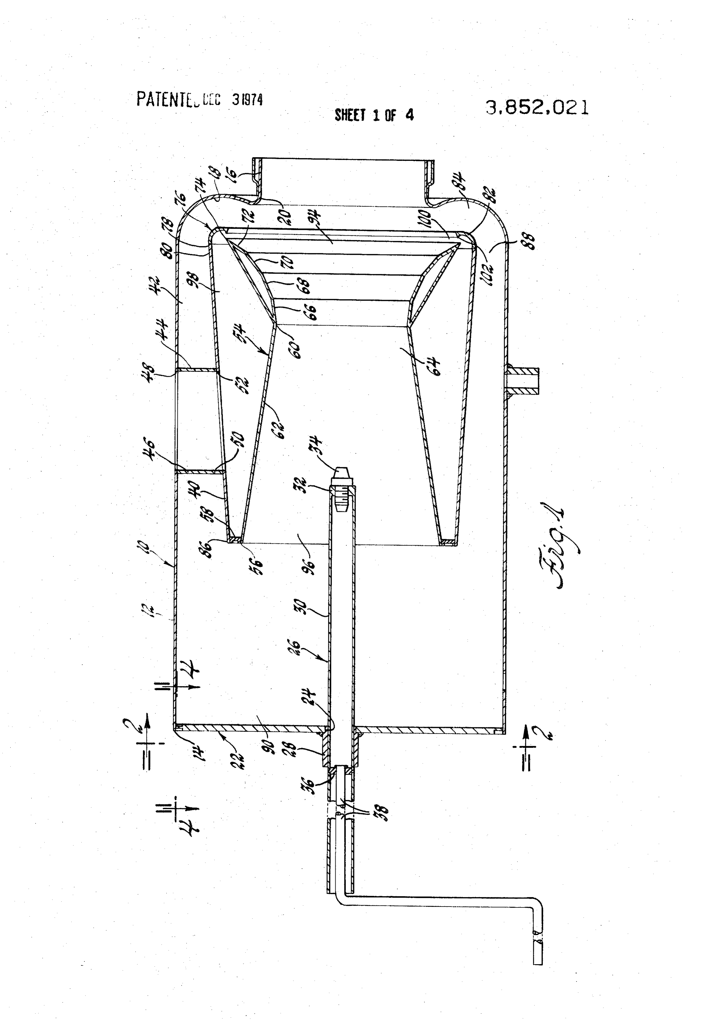
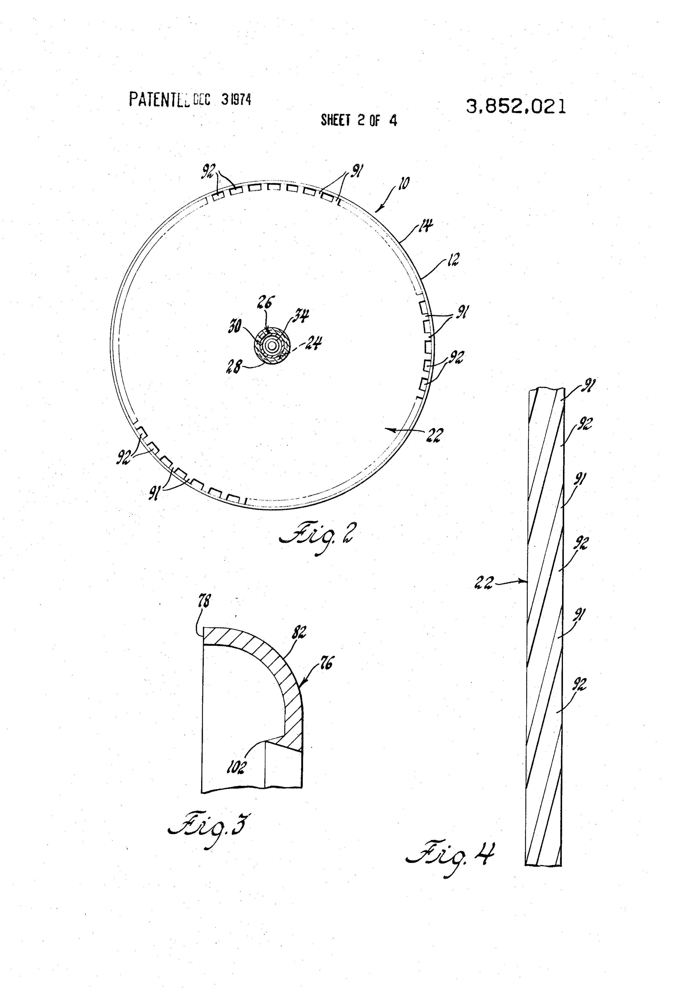
wall jet or Coanda jet has been used to obtain a high FIG. 1 is a view in vertical cross section of a combus ratio of recirculated products to primary combustion tor assembly including the present invention; air flow. In the attached jet type recirculation combus 5 FIG. 2 is an end elevational view looking in the direc tor it is usually necessary to employ a separate means tion of the arrows 2-2 in FIG. : for flame stabilization such as a flow dividing orifice. FIG. 3 is an enlarged, fragmentary sectional view of However, by use of the present invention it has been a nozzle lip in the assembly of FIG. 1; demonstrated that the recirculation flow induced by FIG. 4 is a sectional view taken along the line 4-4 swirl can support stable combustion without the neces 20 of FIG. 1 looking in the direction of the arrows; sity for a separate flame holder. FIG. 5 is a longitudinal cross sectional view of a sec In the subject invention it is proposed that a combus ond embodiment of the invention;
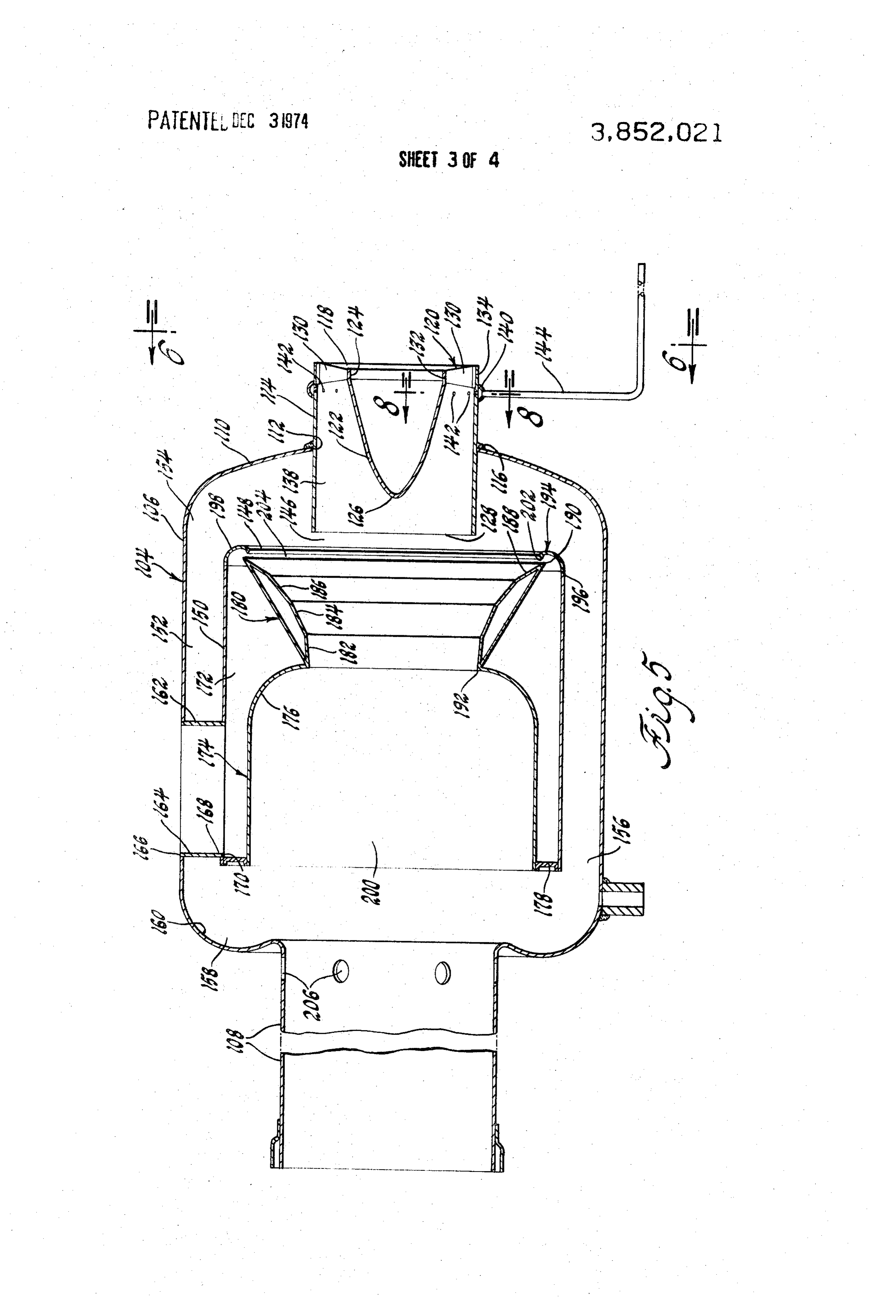
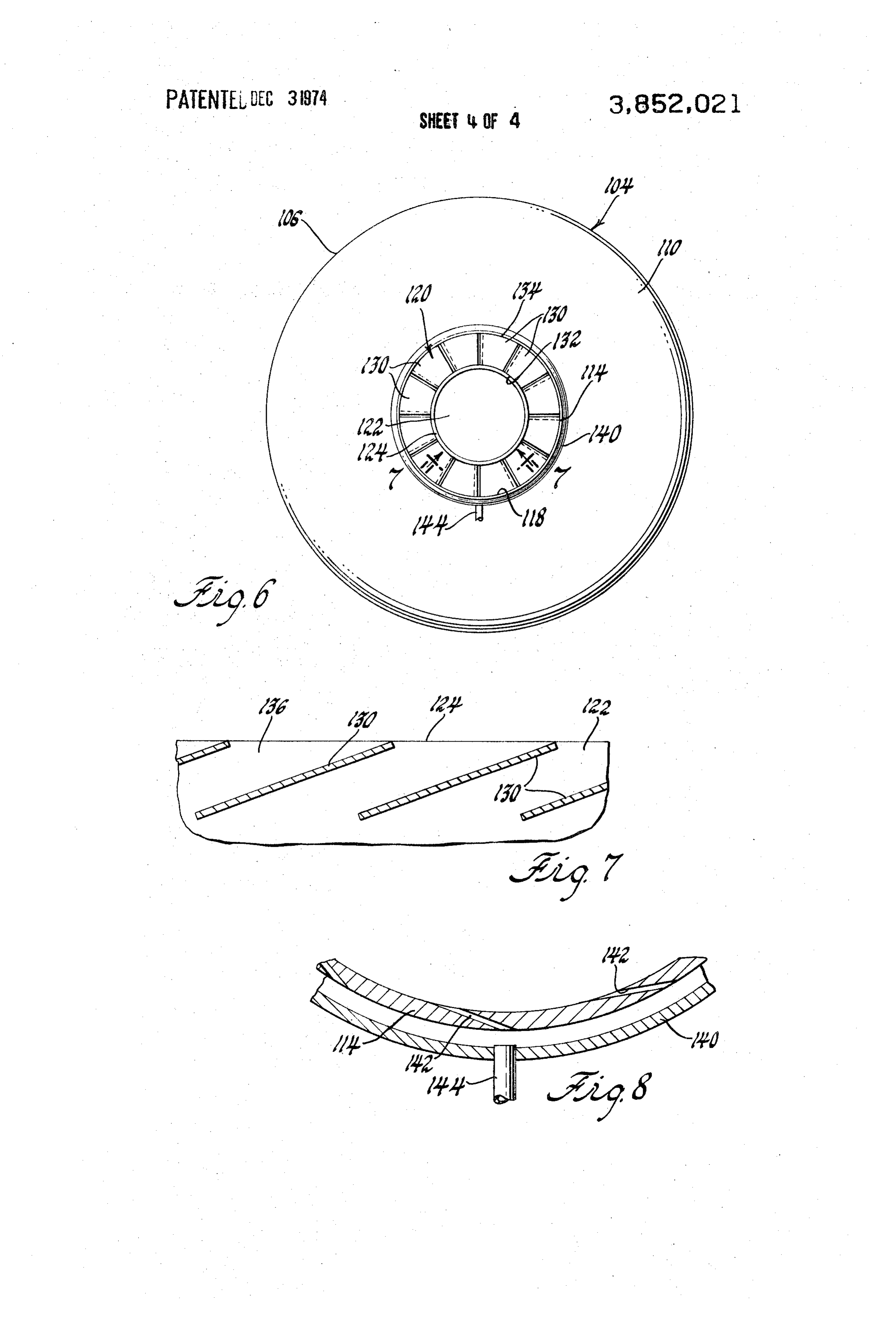
tor design employ both attached jet and swirl effects FIG. 6 is an end elevational view taken along the line operating in conjunction to produce recirculation with 6-6 of FIG. 5 looking in the direction of the arrows; performance which is superior to designs in which ei 25 ther of these effects are used separately to cause recir FIG. 7 is a cross sectional view taken along the line culation. Specifically, combustor assemblies employing 7-7 of FIG. 6; and only swirl effects to induce recirculation have demon FIG. 8 is an enlarged fragmentary vertical sectional strated smaller quantities of recirculation than equiva view taken along the line 8-8 of FIG. 5 looking in the lent designs employing attached jet pumping. On the direction of the arrows.
other hand, the attached jet types employ flame holders Referring now to FIG. 1, a combustor assembly 10 is which increase system pressure loss and limit recircula illustrated having an outer casing 12 with an inlet end tion. 14 and an outlet tube 16 on the opposite end thereof. An object of the present invention is to combine the The outlet end 16 is joined to the outer diameter of the actions of jet pumping and swirl effects in a combustor 35 outer casing 12 by an annular section defining a curved assembly to produce an improved recirculation flow reentrant surface 18 around the inner end 20 of the pattern therein for inducing recirculation through a pri outlet tube 6.
mary combustion zone into a premixing chamber for A swirl plate 22 is located in the inlet end 14 of the prevaporization of fuel particles prior to passage into 40 outer casing 12. It includes a central opening 24 there the primary combustion chamber to reduce emissions through in which is supported a fuel nozzle assembly from the combustor and to reduce pressure loss across 26. Fuel nozzle 26 more particularly includes a bushing the assembly. 28 welded at one end thereof to the outer surface of the Another object of the present invention is to improve plate 22 around the opening 24 therein. An elongated the blow out characteristics of a combustor assembly 45 nozzle tube 30 is supportingly received by the bushing operating under lean fuel-air ratios by the provision of 28 and is directed from exteriorly of the plate 22 into a swirl producing means directing primary air into a the interior of the outer casing 12. The tube 30 has an mixing chamber along with fuel with the swirl device internally threaded fuel nozzle adapter 32 secured on producing a recirculation pattern through a primary one end thereof into which a fuel distributing nozzle 34 combustion chamber into the mixing chamber to in 50 is threadably received.
crease prevaporization of fuel in the mixing chamber Additionally, the nozzle tube 30 has a tube transition and by the further provision of jet pumping means di adapter 36 located therein that supportingly receives recting a second portion of primary air with respect to the open end of a fuel supply tube 38 that is directed the recirculating pattern produced by the swirl means from that point exteriorly of the nozzle tube 30 for con to increase the quantity of recirculation between the nection to a suitable fuel supply source. primary combustion chamber and the mixing chamber 55 A combustion chamber liner 40 of increasing diame to increase prevaporization therein. ter from end-to-end thereof is located within the outer Still another object of the present invention is to im casing 12 in spaced relationship with the inner surface prove the operation of a combustor assembly of the thereof to define an annular external recirculation flow type having an outer casing defining a premixing en 60 passage 42 therebetween. The combustion liner 40 is trance chamber and including a combustor liner lo supported in its spaced relationship by six equally cir cated in spaced relationship to the outer casing to de cumferentially spaced ducts 44 each connected at an fine an annular recirculation chamber, therebetween outer opened end 46 thereon to the outer surface of the and wherein swirl means are provided to produce a re casing 12 around a primary air inlet opening 48 therein. circulation pattern through a combustion chamber 65 An opposite inner opened end 50 of each of the ducts within the liner and the annular chamber for heating 44 is connected to the outer surface of the combustion the air-fuel mixture in the mixing chamber to produce liner 40 around an inlet air supply opening 52 therein. prevaporization therein by the further provision of jet
Page 7scan →
An annular deflector plate S4 is located concentri a reverse axial recirculation flow through the combus cally of and interiorly of the combustion liner 40. It in tion chamber. The remainder of the primary air which cludes an entrance end 56 thereon secured to the lead enters a combustor assembly 10 through the ducts 44 ing edge of the combustion liner 40 by means of a cir into the plenum 98 for discharge through the gap 100 cular inner body plug 58. produces an internal Coanda jet flow across the transi The deflector plate 54 converges radially inwardly tion surfaces which adheres thereto. The swirl compo from the inlet end of the combustion liner toward the nent recirculation represents a driving force to increase longitudinal axis thereof to a reduced diameter at 60 the rate of recirculation over combustors having a jet defining a diffuser section 62 at one end of a primary flow pattern alone. Furthermore, the jet produced by combustion zone 64 within the inner deflector plate 54. 10 the nozzle gap 100 and the adhering flow thereof across From the reduced diameter 60 thereof the deflector the transition surfaces results in a relatively cool non plate 54 includes a plurality of transition surfaces 66, swirling driving force that surrounds relatively hot 68, 70, 72 each being directed at a greater outwardly swirling recirculation gas which is directed through the diverging angle with respect to the longitudinal axis of core of the combustion chamber. This tends to pro the combustion chamber liner 40 from the reduced di 15 mote mixing between the two streams at their interface ameter 60 of the plate to a maximum outer radial diam with a resultant entrainment which produces an im eter 74 thereon. proved rate of recirculation flow through the combus An annular nozzle lip 76 has one end 78 thereon tion chamber. This recirculation flow which is heated welded to a large diameter end 80 of the combustion by combustion within the combustion chamber 64 en liner 40. It further includes a curved outer surface 82 20 ters the mixing chamber 90 where it swirls with respect thereon cooperating with the curved reentrant surface to the fuel droplets directed from the nozzle 34 to be 18 to form a return path 84 from the annular passage intimately mixed therewith to produce prevaporization 42 into the outlet end of the primary combustion zone of the fuel supply before it enters the combustion 64. chamber. Within the combustion chamber, the By virtue of the provision of a large diameter outlet 25 prevaporized and mixed air-fuel components produce end 80 of the combustion liner 40, the annular passage a stable combustion process. By virtue of the pattern 42 between the combustion liner 40 and the outer cas described above and the premix, prevaporization of the ing 12 has a decreasing cross sectional flow area from air fuel within the mixing chamber 90 relatively lean an inlet end 86 thereon to an outlet end 88 thereon air-fuel ratios can be introduced into the combustion which merges with the return path 84 thereby to pro 30 chamber without undesirable blow out of the combus duce increased velocity of recirculation flow from an tion process at zone 64.
inlet mixing chamber 90 formed within the outer casing In combustion devices of the type having swirl in 10 upstream of the primary combustion zone 64 duced recirculation paths therethrough pressure losses formed within the combustion liner 40 and the deflec tor plate 54. 35 which tend to limit the quantity of recirculation flow are associated with a 180 change of flow at both axial
Primary air flow into the mixing chamber 90 is ends of an external recirculation flow path. In the pres through a plurality of swirler vanes 91 defining equally ent invention, however, pump means are intimately as spaced grooves 92 formed in the outer periphery of the sociated with each of the turning processes, namely, plate 22 at circumferentially spaced points there the swirl grooves 92 at one end of the recirculation around. Each of the grooves, as best seen in FIG. 3 is path and the jet producing gap 100 at the opposite end formed at an angle with respect to the axis of the plate thereof. It is known that losses associated with an accel 22 so as to produce a swirl pattern of primary air flow erating flow process such as a nozzle tend to be lower into the chamber 90 which will mix with fuel distrib than with a decelerating or stagnating flow process uted from the nozzle 34 prior to passage into the pri 45 such as a diffuser. Dividing the flow pumping or accel mary combustion zone 64. erating actions in the present invention between the The swirl pattern produced by the grooves 92 in two ends of the combustion chamber 64 will materially cludes a component of velocity tangential to the inner reduce the overall pressure loss otherwise resisting re surface of end 14. It will be directed through the annu circulation flow through the combustion chamber for lar passage 42 from the inlet 86 to the outlet 88 thereof 50 use in prevaporization of fuel supply to the combustor thence through the return path to produce a reverse assembly 10. Thus, by virtue of the aforedescribed ar axial recirculation through the primary combustion rangement, a given quantity of recirculation is obtained zone 64 from an outlet end 94 thereof to the inlet end at a lower overall combustor pressure loss. 96 thereof. A second quantity of primary air is directed A further advantage of the aforedescribed arrange through the ducts 44 into a plenum 98 formed between 55 ment is that it is not absolutely necessary to introduce the deflector plate 54 and the combustion liner 40. The separate dilution air at a downstream location as is primary air is then discharged through an annular gap common practice in air-fuel combustor apparatus. The 100 formed between the maximum radially outer diam relative stability of a layer of swirling primary air adher eter 74 on the plate 54 and the inner annular edge 102 ing to the inner wall of the combustion chamber as pro of the nozzle lip 76 to produce a jet stream that adheres 60 duced by the Coanda nozzle effect will be delayed to to the transition surfaces 68 through 72 at a point radi a position relatively downstream of the primary com ally outwardly of the reverse axial recirculation flow bustion zone 64 to serve this purpose. produced by the swirl grooves 92 at the opposite end A further feature of the invention is that the gap of of the combustor assembly. the Coanda nozzle is at a central location with the com Thus, the primary or fresh air enters the system at the bustion chamber. This location is preferred over an ar grooves 92 to produce a general pattern of axial recir 65 rangement wherein the gap is on the external portion culation flow from the mixing chamber 90 and the an of the inner deflection surface. Such an arrangement nular chamber 42 where the flow reverses to produce would cause a diffusion section downstream of the jet 8 mixing section to have a higher wetted perimeter per lar channel supply conduit 140 that has the edges unit of cross sectional area than for an internal diffus thereof welded to the outer surface of the swirler tube ing section as illustrated in the present invention. As 114 in overlying relationship with a plurality of circum shown, the confinement of the high velocity portions of ferentially located fuel supply openings 142 in the tube the recirculation flow path to the internal portion of the 114. A fuel supply conduit 144 is connected to the an combustion chamber tends to reduce viscous losses nular conduit for directing fuel into the interior 138 over a system, where the jet is located externally through the holes i42 downstream of the swirler vanes thereof.
130 to produce premixing of the fuel and primary air
Another inherent advantage of the internal jet loca therein. The mixed air-fuel passes into a prevaporiza tion is that the jet flows into a region of decreasing O tion mixing chamber 46 that is immediately upstream available area from the maximum diameter location 74 of the inlet 148 of a tubular combustion liner 150. As to the reduced diameter portion 60 of the internal de in the first embodiment, the tubular liner 150 is located flector plate S4 in a direction normal to flow. This re in spaced relationship radially inwardly of the inner sults in a reduced tendency for jet separation and/or re surface of the outer casing 106 to form an annular axial versal of the direction of the entrained flow velocity. 5 recirculation passage 152 therebetween having an inlet A further advantage of the arrangement in the pres 154 in communication with the premix chamber 146 ent invention is that in systems that employ recircula and an outlet 156 therefrom leading to an annular cur tion induced by swirl components only, there is a sec vilinear passage 158 formed by a curved surface 160 of ondary recirculation between the combustion zone the outer casing 106 between the outer diameter products and the incoming swirling primary air. This is 20 thereof and the outlet tube 08 thereof. distinct from the recirculation due to reversal of the As in the first embodiment, the liner 150 is supported axial velocity of the central vortex in swirl recirculation within the outer casing 106 by six equally spaced cir systems. This secondary recirculation is associated, in cumferential ducts 162 each having an opened inlet cases of combustion with swirl only, with mixing 164 connected to the outer casing at an opening 166 around the peripheral boundary between the primary 25 therein. An opposite open end 168 is connected to the swirling flow and the fuel-air mixing zone. This secon inner liner 150 at an opening 170 therein to define a dary mixing can account for some of the undesirable flow path for primary air into a plenum space 172 features with respect to exhaust emissions found in formed between the combustion chamber liner 150 and combustor designs depending solely on swirl effects to an inner deflector plate 174.
induce recirculation. In the present arrangement, there 30 The inner deflector plate 174 includes a cup-shaped is a better control over this secondary recirculation ef segment 176 with an opened end thereon sealed with fect because of the attached wall jet produced by the respect to the downstream end of the liner 150 by an gap 100 as directed across the inner surface of the de inner body plug member 178 to close one end of the flector 54. By optimization of the additional geometric plenum space 172. The deflector plate 174 further in variable defined by the surface of the deflector 54 and 35 cludes an entrance transition section 180 having a plu the location of the jet gap, it is possible to confine the rality of staggered surfaces 182, 184, 186, 188 thereon. secondary recirculations to regions outside the fuel-air Surface 182 has a maximum diameter at 90 that is the mixing Zone. entrance to the transition section 180. Each of the sur FIGS. 5 through 8 illustrate a second embodiment of 40 faces 82 thru 188 are formed angularly with respect the invention including a combustor assembly 104 hav to the adjacent surface to form an inwardly converging ing an outer casing 106 with an outlet tube portion 108 surface from the maximum diameter 190 to a restricted thereon and a curved inlet dome 110. A central open diameter portion 192 of the deflector plate 174 located ing 12 in the inlet dome 110 supportingly receives a between the transition section 180 thereof and the cup swirler tube 114 which is welded thereto at 116. shaped outlet segment 176 of deflector plate i74. The swirler tube i4 has an opened entrance end 118 45 As in the first embodiment, the transition section 180 thereon for supply of primary air through a swirler as is located immediately downstream of an annular Co sembly 120 which includes a center body 122 having a anda effect nozzle lip 194 that has one edge 196 large diameter inlet end 124. End 124 is spaced with thereon connected to the upstream end of the combus respect to the inner surface of the swirler tube 114 at tion chamber liner 150 and includes a curved surface the opened end 18 thereof. Body 122 has a decreasing 50 198 thereon cooperating with the curved dome 110 to diameter to define a nose portion 126 terminated cen form a curvilinear path from the prevaporizing mix trally of an outlet end 128 of the tube 114. The swirler chamber 146 into the inlet 148 of the liner. This leads center body 22 is connected to the inner surface of axially into a primary combustion zone 200 within the the swirler tube 114 adjacent the open end 118 thereof deflector plate 174. The lip 194 has an edge 202 by a plurality of swirler vanes 130 which are located at circumferentially spaced points along the periphery of thereon spaced closely adjacent the maximum diame of the transition section 180 to form a gap 204 the inlet end 124. Each of the swirler blades has a root therebetween which directs primary air received from portion 132 thereof connected to the center body 122 the ducts i62 as an annular jet across the transition sur and a tip portion 134 thereof fixed to the inner surface 60 face 180 to form a wall adhering jet stream from the of the tube 114 at the open end 118.
As best seen in FIG. 7, each of the swirl vanes has a maximum diameter 198 to the reduced diameter 192. passage 136 formed therebetween which is directed at As in the first embodiment, during the combustion an angle with respect to the axis of the center body 122 process, primary air and fuel are directed into the to produce a clockwise swirl as viewed from the swirler 65 swirler assembly 120 which has a tangential component end of the liner, elevational view, in FIG. 6. formed at the outlet end 128 of the tube 114. The pre Fuel is directed into the interior 138 of the swirler mixed fuel and vapor components are directed through tube downstream of the swirler vanes 130 by an annu the gap of the premix chamber 146 to the inlet 148 of 9 the combustion liner 150 as a swirl pattern through the -Continued combustion chamber where it is heated and the com bustion gases in part are returned in a reverse, external Item Specification recirculation flow through the curved passage 158 and 4 inches outlet diameter the annular passage 152 back to the premix chamber Nozzle lip 76 6.875 inches diameter 146 where the gases will heat the tube 114 and the Nozzle gap 100 .90 inches mixed air-fuel components passing through the gap of Plate 22 9.895 inches I.D. 52 peripheral grooves the chamber 146 so as to prevaporize fuel particles Groove 92 Width .092 inches prior to passage into the combustion zone 200.
As was the case in the first embodiment, recircula 10 tion passes through a 180 path from the annular pas While the embodiments of the present invention, as sage 152 to the inlet 148 and the pumping action of the herein disclosed, constitute a preferred form, it is to be jet produced by the gap 204 will reduce pressure losses understood that other forms might be adopted. at this point in the recirculation flow so as to increase What is claimed is:
the rate of recirculation in the device to improve preva 15 1. A combustor assembly comprising an outer casing porization of fuel particles prior to passage into the having an inlet and an outlet therein, a combustion combustion zone 200. liner located within said outer casing and spaced with Furthermore, the jet pumping action through the gap respect thereto to form an annular external recircula 204 will form a cool envelope around the swirl pattern tion passage therebetween, means including an inner confining the high velocity portions of the recirculation 20 deflection surface within said combustion chamber flow path to the internal walls of the combustion cham liner for forming a primary combustion zone therein ber thereby to reduce viscous losses as compared to having an inlet end and an outlet end, means forming pure swirl type recirculating systems. As in the first em a mixing chamber upstream of the inlet end of said pri bodiment, the jet flow from the gap 204 flows into a re mary combustion zone, means on the inlet end of said gion of decreasing available area normal to flow to re 25 outer casing for producing a swirl pattern within said sult in a reduced tendency for jet separation or reversal mixing chamber directed through said annular passage of the direction of the entrained flow velocity. and said primary combustion zone to direct hot gases The jet induced recirculation in the embodiment of therefrom into said mixing chamber for prevaporiza FIGS. 5 thru 7 is across the inner surface of the deflec tion of air-fuel mixture therein, means including said tor plate 174 thence the curved passage 158 back 30 liner defining a plenum within said outer casing, means through the annular passage 152 and thence to the inlet for directing primary air from exteriorly of said outer 148. This will heat premix components in the chamber casing into said plenum, an annular nozzle lip Sup 146 to imrpove the combustion process in the chamber ported on said liner in spaced relationship to said de 200. flector plate to define an annular gap therebetween for In this embodiment of the invention secondary air 35 passage of primary air from said plenum into said com openings 206 are located adjacent the transition be bustion zone for directing a quantity of primary air tween the outlet tube 108 and the curved surface 160 across the inner surface of said inner deflection surface of the outer casing 106 to produce further combustion to improve the recirculation flow of hot gases from said of the fuel-air components prior to discharge from the 40 primary combustion zone into said mixing chamber system. thereby to reduce overall pressure drop from the inlet In the first embodiment the recirculation pattern is end to the outlet end of said outer casing. characterized by an external recirculation flow pro 2. A combustor assembly comprising an outer casing duced by the swirl pattern through the annular passage having an inlet and an outlet end thereon, a tubular 42. Additionally, there is an internal recirculation pat 45 combustion chamber liner located within said outer tern produced by jet flow from the gap 100. Addition casing and being spaced therewith to form a radially of an attached jet pumping system in the outer recircu outer annular recirculation passage between inlet and lation loop would augment recirculation in the cham outlet ends of said outer casing, means forming a pri ber 42 in the same way that the addition of an internal mary combustion chamber within said liner having a pump augments recirculation of the inner loop. 50 inlet end and an outlet end thereto, means forming a The basic purpose of the aforedescribed invention is mixing chamber upstream of said combustion chamber, that there is included a unique combination of two means including first pump means at the upstream end methods of producing recirculation; namely, jet pump of said combustion chamber for producing a swirl pat ing and blade induced swirl. The combination yields tern within said mixing chamber to promote entrain unique combustor performance advantages over more 55 ment of air and fuel therein, said swirl pattern produc conventional approaches that include recirculation de ing a reverse axial recirculation of flow from said com pendent upon one of the effects alone. bustion chamber through said passage into said mixing In the embodiment of FIG. 1, which is representative chamber for increasing the temperature of air-fuel par of the present invention, the combustor assembly 10 ticles therein, means including said liner defining a has the following mechanical characteristics. 60 plenum within said outer casing in surrounding rela tionship to the combustion chamber, means for direct ing primary air from exteriorly of said outer casing into tem Specification said plenum, means including an annular nozzle lip sup ported on one end of said liner to define an annular gap
Outer casing 40 17 inches length 65 communicating said plenum chamber with said com
Combustion chamber liner 7 inches inlet diameter bustion chamber at one end of said liner for directing Diffuser section 62 8 inches outlet diameter a second quantity of primary air through said combus 6 inches inlet diameter tion chamber to enhance said swirl induced reverse re
Page 10scan →
9 O circulation of gases from said combustion chamber into of said diffusion section directed into said annular pas said mixing chamber and to further promote a 180 re sage and toward the outlet for producing a reverse axial versal of flow from said annular chamber at said one recirculation from the outlet end of said combustion end of said liner into said combustion chamber to re chamber to the inlet end thereof, means for directing duce pressure losses from the inlet end to the outlet end primary air through said gap for producing attached of said outer casing due to recirculation produced by wall entrainment of primary air across the diverging said swirl pattern.
3. A fuel combustor assembly comprising an outer section tion of said deflection plate for promoting recircula flow through the primary combustion zone, said casing having an inlet end and an outlet end, means flow of primary forming a mixing chamber downstream of said inlet O of swirl inducedair through said gap promoting reversal end, a combustion liner located within said outer casing the outlet end of saidthrough flow said annular passage into defining a primary combustion zone therein down plate grooves promoting reversal ofchamber, combustion said swirl stream of said mixing chamber, swirl means for direct outwardly of said diffusion section inaxial recirculation a reverse direc ing a first portion of primary air in a swirl pattern from tion through said annular passage thereby the inlet end of said casing into said mixing chamber, 15 overall pressure drop between the inlet endtoand reduce fuel supply means at said inlet end for directing fuel outlet end of said outer casing due to recirculationthe of into said swirl pattern to premix air and fuel within said mixing chamber upstream of said primary combustion flow through said primary combustion zone for produc zone, an inner deflection plate located radially inward ing improved prevaporization of air-fuel mixture within of said combustion liner including a radially outwardly 20 said mixing chamber.
5. A combustor assembly comprising an outer casing flared inlet end thereon and a converging surface defin having an inlet end and an outlet end, a combustion ing a diffusion section, said plate including a radially liner supported within said outer casing between the diverging section at the opposite end of said combus opposite ends thereof and defining therewith an annu tion liner to define a decreasing cross sectional flow area from the outlet end of the combustion liner in the 25 lar passage located radially outwardly of said combus direction of the diffusion section therein, an annular tion liner between the inlet and outlet ends of said passage formed between said combustion liner and said said outer casing, swirl means supported on the inlet end of outer casing communicating said mixing chamber with bodyouter casing including an outer tube and a center portion having a decreasing diameter outer sur the outlet end of said outer casing, said swirl means face configuration, a large diameter end of said center producing a flow pattern in said annular passage from 30 the inlet end to the outlet end of said outer casing and body being located adjacent one end of said outer tube a resultant reverse axial recirculation of flow through and forming an annular space therebetween, a plurality the diverging section of said inner deflection plate and of swirler vanes supported on the large diameter end of the diffusion section thereon, said swirl means serving said center body portion each inclined with respect to to promote flow from said diffusion section through 35 the longitudinal axis of said outer tube for promoting 180 into said annular passage at one end of said com a swirl pattern from the inlet end of said outer tube to bustion liner, and second pump means at the opposite the outlet end thereof, means directing fuel into said end of said combustion liner for promoting a reverse outer tube immediately downstream of said swirler 180 flow from said annular passage into the diverging vanes to mix air and fuel upstream of said combustion section of said inner deflection surface to promote flow 40 liner, means forming a mixing chamber downstream of of recirculation through the primary combustion zone said outer tube outlet, an inner deflection plate sup during combustor operation while reducing overall ported on said combustion liner forming a primary pressure drop between the inlet and the outlet ends of combustion zone within said liner including an inlet said combustor casing. end and an outlet end, said swirler vanes producing a 4. A combustor assembly comprising an outer casing 45 swirl pattern through said primary combustion zone having an inlet end and an outlet end, a swirl plate clos from the inlet end to the outlet end thereof and a re ing the inlet end of said outer casing including a plural verse axial recirculation of flow through said annular ity of peripheral grooves therein inclined at an angle passage back to the mixing chamber upstream of said with respect to the axis of said outer casing, a mixing primary combustion zone, said inner deflection plate chamber in said casing, a fuel supply nozzle supported 50 having a surface diverging inwardly from the mixing centrally of said plate directed interiorly of said outer chamber to the inlet of said primary combustion zone casing, a combustion chamber liner supported within immediately downstream of said mixing chamber, a said outer casing in spaced relationship therewith to de nozzle lip located radially outwardly of said inwardly fine an annular passage located concentrically fo said diverging inner surface forming an annular nozzle gap, plurality of swirl plate grooves, an inner deflection 55 means for directing primary air into said nozzle gap to plate supported on said combustion liner including an produce an attached wall jet of primary air across said upstream radially outwardly diverging section thereon inwardly diverging surface for promoting reverse flow forming a diffusion section to a primary combustion of recirculation through said annular passage into the zone therein, said fuel nozzle having its outlet tip mixing chamber upstream of the inlet to said primary thereon located within said diffusion section, said inner 60 combustion chamber and to enhance the rate of recir deflection plate including diverging section thereon de culation of flow from the combustion chamber back to fining the outlet end of said combustion zone down the mixing chamber thereby to improve prevaporiza stream of said diffusion section, a jet nozzle lip secured tion of air-fuel particles in said mixing zone prior to to said liner forming a circumferential gap facing up passage into said combustion chamber and to reduce stream of said combustion zone at a point downstream 65 pressure drop from the inlet end to the outlet end of of said diverging section, said swirl plate grooves pro said outer casing.
ducing a swirl pattern in said mixing chamber upstream x: k ck sk k
Provenance
- Collection
- Patents citing this work
- Pages
- 10
- Method
- pdftotext (the PDF's own text layer) + pdftoppm 300dpi page scans
- Patent office record
- patents.google.com →
- Source
- Google Patents citing-documents table
- Assignee
- Gen Motors Corp
- Published
- 1974-12-03
- Transcribed from
- patentimages.storage.googleapis.com →