

patent · US3910749A
Induction burner
7 October 1975
Text
Page 1bibliographic recordscan →
United States Patent (19)
Voorheis
54 INDUCTION BURNER
76 Inventor: James T. Voorheis, 18 Smull Ave., Lake Hiawatha, N.J. O7006
(51) Int. Cl........................................... F23L 17/00
UNITED STATES PATENTS
3, 174,526 3/1965 Von Linde.......................... 431 fl 16 3,516,807 6/1970 West et al........................... 4311 115 3,868,211 2/1975 La Haye et al..................... 431 / 15
Primary Examiner-Carroll B. Dority, Jr.
Attorney, Agent, or Firm-Popper & Bobis
An induction burner for effectively and efficiently burning fuel to supply heat; or alternatively to effi ciently consume contaminants in an air stream prior to discharging the air stream to the atmosphere; wherein the burner is a refractory body having an axial passage for a flame, a plurality of passages conducting air from a combustion chamber to an induction port header, which in turn communicates with the axial passage, a generally radial enlargement in the axial passage, a flame tunnel at one end of the axial passage, the flame tunnel having a diameter less than the radial enlarge ment.
10 Claims, 2 Drawing Figures
avaara
Drawings
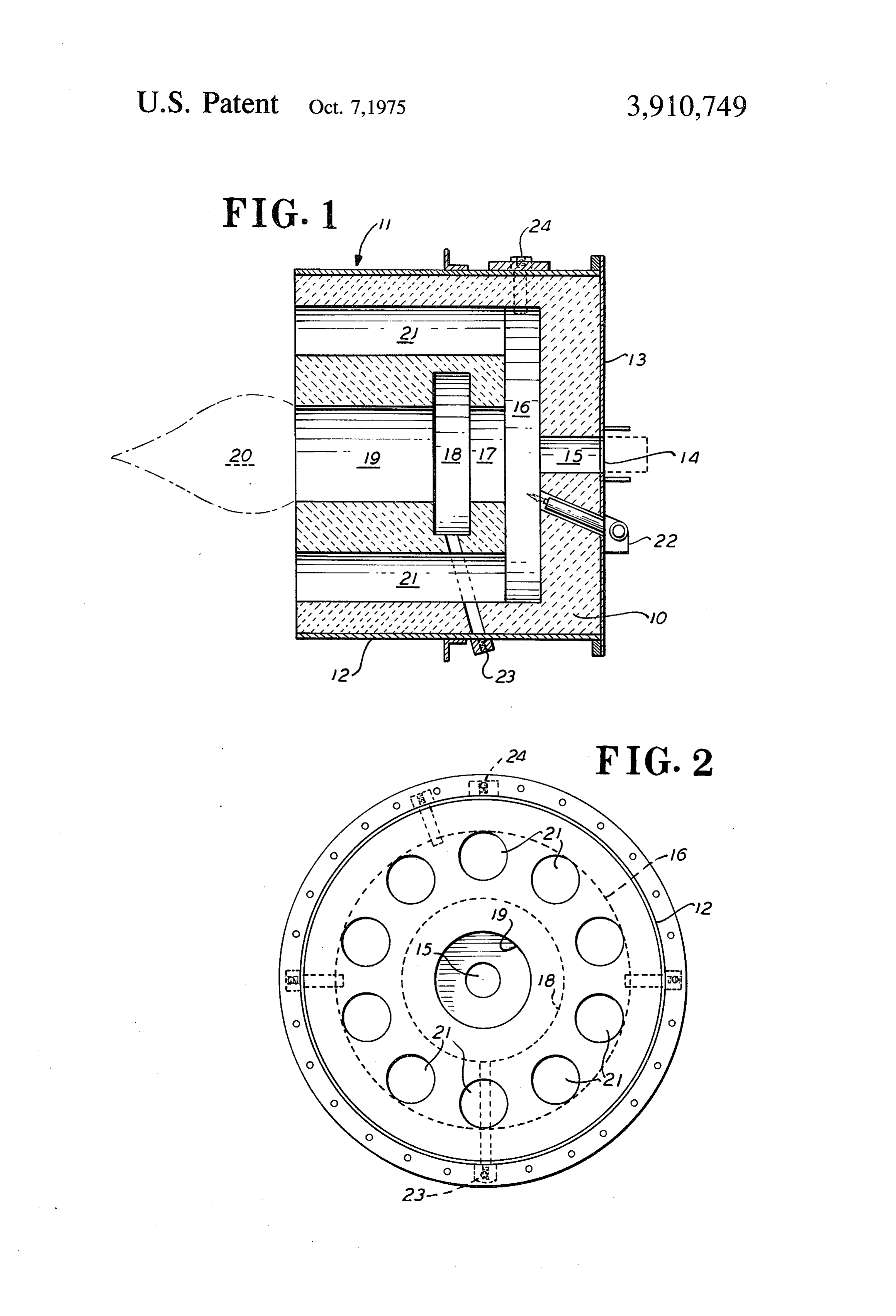
FIG. 2 is a back-end view thereof. support combustion and, indeed, to enter the bores 21 PREFERRED EMBODIMENT and the induction port header 16 to support combus tion.
Page 2drawing sheetscan →
Page 3scan →
INDUCTION BURNER whereby fuel from the fuel supply orifice 14 and air to BACKGROUND OF THE INVENTION support combustion from the first chamber or induc tion port header 16 are conducted into a second cham 1. Field of the Invention ber 18 which is a radial annular cavity 18, which func This invention relates to duct fired induction burners tions as a flame retention chamber. generally, and specifically to duct fired induction burn The second chamber 18 is a flame eddy-cavity. It is ers having therein passages to supply air to support larger than the second passage 17, and defines an area combustion drawing from a combustion chamber to the to capture the flames of combustion in order to prevent point of flame propagation in the burner, and further a flame-out. Beyond the second chamber 18 is a gener to such a burner having a flame eddy cavity adjacent to ally elongated open chamber 19 which defines a flame a flame tunnel which cavity is higher than the flame tunnel wherein combustion occurs and from which is tunnel. sues the flame plume 20.
2. Prior Art Surrounding the flame tunnel 19 in the refractory There are numerous induction burners which have fire-brick lining 10, there are a plurality of tubular been in use for many years. Problems arise from time 5 bores 21, whereby air to support combustion is con to time with their use, in that flame-outs are frequent. ducted from the furnace wall area via induction ports Their design is such that they support combustion in into the bores 21 to the induction port header 16. It will part with clean primary air, which is not necessary to be seen that the bores 21 are spaced away from the support combustion when the burner is being used to plume 20, whereby the products of combustion are not consume contaminants in secondary contaminated air necessarily returned through the bores 21 to the point introduced into a combustion chamber. of the flame propagation. The bores 21 primarily will SUMMARY OF THE INVENTION conduct the air embodying the waste process products from along the walls of a combustion chamber back to
It has been found that an induction burner can be de the point of propagation of the flame. It will be seen vised which utilizes solely to support combustion, the 25 that there is no passage communicating between the atmosphere of the combustion chamber, and predomi flame tunnel 19 and the bores 21 in the refractory nantly that portion of the atmosphere of the combus body, through which air to support combustion is sup tion chamber which has not been subjected to combus plied to the first chamber 16; it is only incidental to the tion. This burner efficiently consumes the undesirable combustion that takes place in the combustion cham contaminants in the air or gases introduced into the 30 ber that products of combustion may in part be re combustion chamber by utilizing such gases to support turned through the bores 21 to the induction port combustion. In addition, this burner is provided with an header or first chamber 16. This burner 11 is primarily anti-flame-out construction in the form of a flame eddy designed for waste gas-streams, wherein the gas stream cavity, whereby the failure of the burner to adequately has undesirable impurities which must be removed or and properly support combustion due to high velocity 35 converted to less undesirable products of combustion gas introduction is substantially and effectively before being discharged to the atmosphere. It is how avoided. ever to be understood that this burner may have, in ad dition other uses.
Description of the drawings
Waste gas-streams carrying undesirable products
The objects and advantages as well as other objects 40 which are to be eliminated from such streams are usu and advantages may be attained by the device shown by ally rich in oxygen to support combustion so that when way of illustration in the drawings in which: such waste gas-streams are supplied to a combustion FIG. 1 is a vertical section view of my induction chamber to which the present burner is attached, there will be ample oxygen in the combustion chamber to
FIG. 2 is a back-end view thereof. support combustion and, indeed, to enter the bores 21 PREFERRED EMBODIMENT and the induction port header 16 to support combus tion.
Referring now to the drawings in detail, the induction It will be further noted that this burner utilizes as a burner 11 is provided with a tubular cylindrical shell primary source of oxygen: the waste gas-stream, in 12, preferably made of steel although other materials order to support combustion, and no provision is made may be used. The shell is provided with a closure plate for the utilization of a secondary source of oxygen at 13 at one end, also preferably steel. the site of the combustion. In this manner, large econo The closure plate 13 has a central circular, axial ori mics are effected in the disposition of the impurities. fice 14 defining a fuel gun port, whereby liquid or gase 55 The burner is provided with a pilot 22 which extends ous fuel is introduced into the burner 11. The shell 12 through the portion of the refractory brick 10 lying surrounds a unitary elongated refractory, body or lining over the closure plate 13, whereby a flame for ignition 10. The body 10 fills the space defined by the shell 12 of gas or oil fuel may be provided in the induction port and the closure plate 13. The refractory body 10 has a header. In order to insure that fuel will not be intro first passage 15 which is a generally radial, small, axial 60 duced continually into the burner 1 if there should be bore in registration with the fuel supply port 14 in the a failure of ignition, a scanner connection 23 is pro plate 13. vided for the flame eddy cavity 18. A scanner applied The first passage 15 communicates with a first cham to this connection would continuously monitor the ex ber 16 in the refractory body 10. This first chamber 16 istence of combustion. There is a further scanner con defines a header for induction ports which hereafter 65 nection 24 which monitors the existence of the pilot will be referred to. The header 16 is radially high and flame. Flame Scanners are well known to the industry. extends nearly to the shell 12. From the first chamber In the event of a failure of the pilot flame, the combus 16, there is a second passage 17, defining a conduit tion in the eddy cavity 18, the scanner will send a signal 4 to the fuel supply source which will immediately cut off b. the first passage, first chamber, second passage, fuel. A burner gun is not shown in the burner 11. It is second chamber, and open chamber being all of a attached at the fuel supply port 14. Such burner flame generally circular, cross-sectional configuration. guns may be in accordance with the many guns now 4. An induction burner according to claim 3 and well known, or may be particularly in accordance with a. the first passage, first chamber, second passage, disclosures in my U.S. Pat. No. 3,758,259 issued Sept. second chamber, and open chamber being dis 1 1, 1973, wherein details of the construction of the posed co-axially.
suitable burner gun are set forth in detail. 5. An induction burner according to claim 1 and The refractory lining of the induction burner may be a. the first chamber and the second chamber having made of any suitable refractory material and which is 10 generally the same width. castable and composed of 47 to 96 per cent alumina. 6. An induction burner according to claim 1 and Typical induction burner dimensions suitable to ac a. the first chamber being radially generally greater complish the purposes of the present invention are as than the second chamber. follows: 7. An induction burner according to claim 1 and The first and second chambers 16, 18 may be 3 15 a. the second chamber being radially generally inches wide. greater than the open chamber. The first chamber 16 should be higher than the sec 8. An induction burner according to claim 4 and ond chamber 18, a typical dimension for the height of a. the elongated open chamber being axially longer the first chamber 16 is 26 inches and the second cham than the second chamber. ber 18: - 14 inches. 20 9. an induction burner according to claim 1 and The elongated open chamber 19 should be less in a. a plurality of additional induction ports at the back height than the second chamber 18 and may be approx face of the body, connected with the header. imately 8 inches high. 10. An induction burner comprising: The second passage 17 communicating between the a. an elongated refractory body, first chamber 16 and the second chamber 18 should be 25 b. a first passage at the front of the body for the intro generally of the same height as the elongated open duction of fuel, chamber 19: - 8 inches. c. a first chamber in the body connected with the first The length of the elongated open chamber 19 should passage, and defining a header for induction ports, be approximately one and one-half to twice its diame d. a second passage in the body communicating with te. the first chamber,
The first passage 15 should be approximately 3 e. a second chamber in the body communicating with inches high. the second passage, and defining a radially dead The first chamber 16 may be typically 26 inches high end flame eddy cavity, and 3 inches wide. Tubular bores 21 communicating f. an elongated chamber having an opening to the between the induction port and the first chamber 16 35 ambient in a back face of the body, connected to should be approximately 18 inches long. the second chamber, and defining a flame tunnel, What is claimed is: said second chamber being substantially larger in a 1. An induction burner comprising: radial direction than said second passage and said a. an elongated refractory body, elongated chamber, b. a first passage at the front of the body for the intro 40 g. an induction port open to the ambient and located duction of fuel, in the back face of the body adjacent the opening c. a first chamber in the body connected with the first in the elongated chamber, connected with the passage, and defining a header for induction ports, header, d. a second passage in the body communicating with h. a metal shell surrounding the body, the first chamber, 45 i. a front plate on the front of the body, e. a second chamber in the body communicating with j. the body having a generally circular cross-sectional the second passage, and defining a radially dead configuration, end flame eddy cavity, k. the first passage, first chamber, second passage, f. an elongated chamber having an opening to the second chamber, and open chamber being all of a ambient in a back face of the body, connected to generally circular, cross-sectional configuration, the second chamber, and defining a flame tunnel, l. the first passage, first chamber, second passage, said second chamber being substantially larger in a second chamber, and open chamber being dis radial direction than said second passage and said posed co-axially, elongated chamber, m. the first chamber and the second chamber having g. an induction port open to the ambient and located 55 generally the same width, in the back face of the body adjacent the opening n. the first chamber being radially generally greater in the elongated chamber, connected with the than the second chamber, header. o. the second chamber being radially generally 2. An induction burner according to claim 1 and greater than the open chamber, a. a metal shell surrounding the body, 60 p. the elongated open chamber being axially longer b. a front plate on the front of the body. than the second chamber, 3. An induction burner according to claim 1 and q. a plurality or additional induction ports at the back a. the body having a generally circular cross-sectional of the body, connected with header.
configuration,
Provenance
- Collection
- Patents citing this work
- Pages
- 4
- Method
- pdftotext (the PDF's own text layer) + pdftoppm 300dpi page scans
- Patent office record
- patents.google.com →
- Source
- Google Patents citing-documents table
- Assignee
- James T Voorheis
- Published
- 1975-10-07
- Transcribed from
- patentimages.storage.googleapis.com →