

patent · US3915625A
Heat injector gas burner
28 October 1975
Text
Page 1bibliographic recordscan →
United States Patent (19)
Hapgood
54 HEAT INJECTOR GAS BURNER
(75. Inventor William H.o Hapgood, Concord,
(73 Assignee: Raytheon Company, Lexington,
Mass.
(52) U.S. Cl.................................. 431/353; 431/264 (51 int. Cl’.......................................... F23D 15/02
UNITED STATES PATENTS
2,701,608 2/1955 Johnson.......................... 431/353 X 3,182,711 5/1965 Robb.............................. 431/263 X
3,275,057 9/1966. Ward.............................. 431/353 X Primary Examiner-Edward G. Favors
Attorney, Agent, or Firm-Harold A. Murphy; Joseph D. Pannone; John T. Meaney
A heat injector gas burner for producing an extended flame for heating a remote area, comprising an elon gated tubular casing having therein a short tubular flame holder into which gas is introduced, means at one end of the casing for metering the flow of air into the casing and simultaneously into the adjacent end of the flame holder, and ignition means within the casing external to and adjacent the opposite end of the flame holder, which metering means produces substantially uniform velocity of air flow within the casing both in side and outside the flame holder.
3 Claims, 3 Drawing Figures
SUPPLY
SS - aZZZZZZZ
Drawings
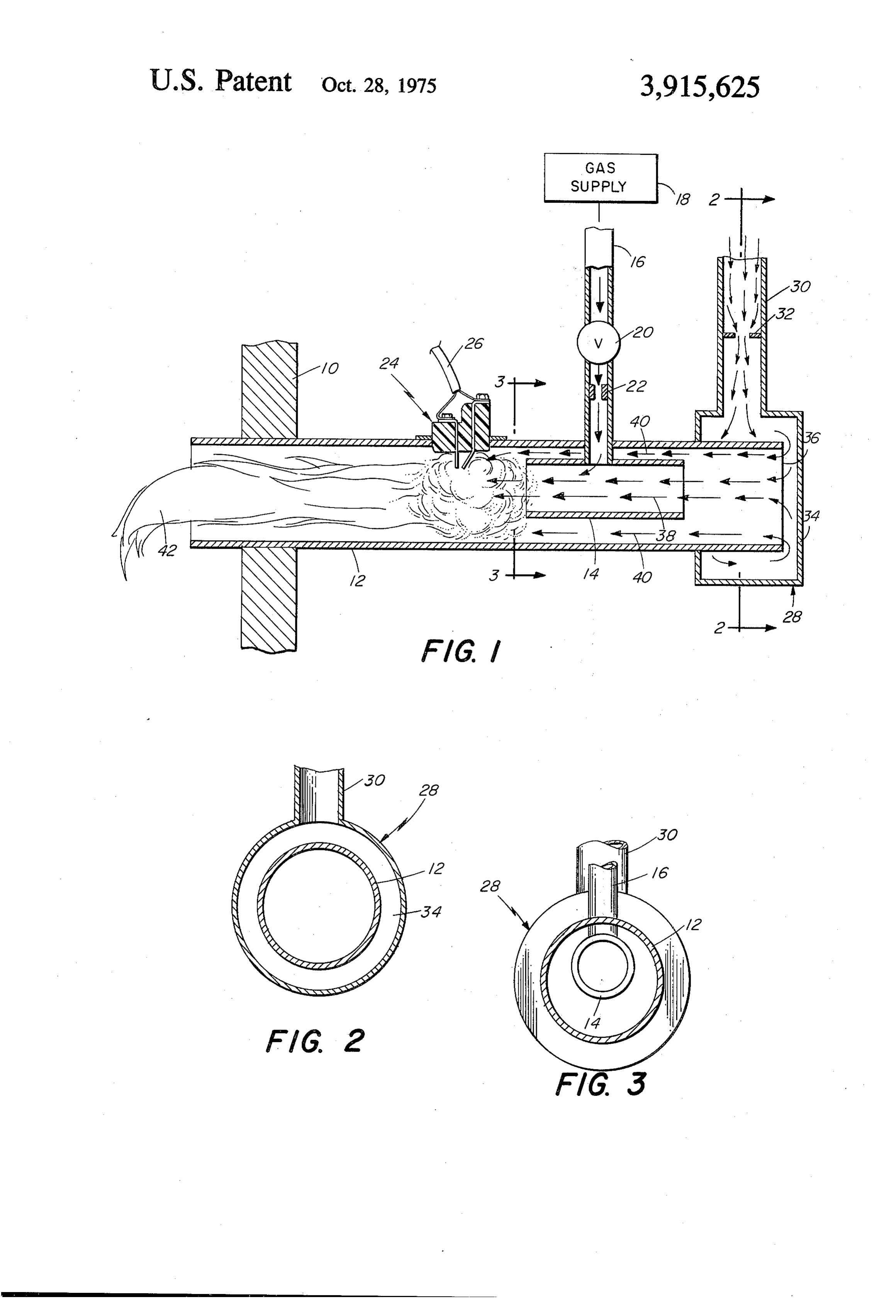
FIG. 2 is a sectional view taken on line 2-2 of FIG.
Page 2drawing sheetscan →
Page 3scan →
HEAT INJECTOR GAS BURNER FIG. 1 is a vertical sectional view of a burner struc BACKGROUND OF THE INVENTION ture embodying the invention;
FIG. 2 is a sectional view taken on line 2-2 of FIG.
In the manufacture of gas-fueled devices such as in 1 looking in the direction of the arrows; and cinerators, for example, it is often highly desirable that FIG. 3 is a sectional view taken on line 3-3 of FIG. the burner thereof be located in a chamber remote 1 looking in the direction of the arrows. from the chamber in which combustion takes place.
This thus requires that the burner be designed so as to DESCRIPTION OF THE PREFERRED efficiently produce an exceptionally long flame which EMBODIMENT will extend into the remote combustion area. 10 Referring more particularly to the drawings wherein Burner structures have been made which employ an like characters of reference designate like parts outer tubular casing which encloses a parallel short tu throughout the views, the burner 10 shown in FIG. 1 is bular flame holder, with air being introduced simulta adapted to be mounted, for example, in a chamber neously into adjacent ends of the casing and flame which is located on one side of a wall or partition 10 holder. Gas is introduced into the flame holder for mix 15 and to produce a flame which extends well into the ing with the air therein for primary combustion when chamber on the opposite side of the partition. ignited adjacent the exit end of the flame holder. Sec The burner comprises a casing 12 which has one end ondary combustion is sustained by the air flowing be protruding through an opening in the partition. Casing tween the flame holder and casing. U.S. Pat. No. 10 is tubular in shape and has within it spaced substan 3,486,835 is an example of such a known burner struc tially inwardly from the opposite end thereof, a flame ture. holder 14 which is in the form of a short tubular mem However, in known burners of this character it has ber of substantially smaller diameter than casing 12. been found difficult to regulate or adjust the quantity Flame holder 14 extends parallel with casing 12 and is and velocity of primary air within the flame holder for located somewhat closer to the top than to the bottom most efficient ignition. One attempt to solve this prob 25 of the casing as shown clearly in FIGS. 1 and 3. lem is made by providing an apertured closure in the A gas supply pipe 16 is connected at one end to a entrance end of the flame holder, as shown in U.S. Pat. manifold or other source of gas 18, with its other end No. 2,072,731. Such a device, however, is not entirely projecting through an opening in casing 12 and con satisfactory for many reasons. nected directly into the flame holder 14 whereby gase 30 ous fuel may flow from the supply 18 into the flame
Summary of the invention
holder 14. The pipe 16 may contain a conventional
In accordance with the present invention the forego valve 20 and orifice 22 if desired for controlling the ing and other problems are improved upon or over flow of the fuel.
come by the provision of a burner structure employing An ignitor 24 of any selected type, such as the Fen a short tubular flame holder within an elongated tubu 35 wal spark ignitor shown, is mounted in the casing adja lar casing wherein air flow into the adjacent entrance cent the inner end of the flame holder, and is adapted ends of the casing and flame holder is controlled or me to be connected to a suitable source of electrical en tered by a reversing fitting which achieves uniform air ergy in any conventional manner through cable 26. velocities within both the casing and flame holder and The inner end of the casing 12 is enclosed within a provides efficient quantity of primary air for efficient 40 reversing box 28, to be described, to a side wall of ignition. Gas is introduced into the flame holder and which is connected one end of a duct 30 which is con such air is necessary for ignition of gas-air mixtures em nected at its other end to a plenum or other source (not anating from the exit end of the flame holder. shown) of forced air flow. Air passes through the duct The reversing fitting comprises a box which is 45 in quantity and velocity controlled by a suitable orifice mounted in spaced relation with and over the end por 32 therewithin and flows into the reversing box 28 and tion of the casing. Air is metered through a duct into thence into the adjacent end of the casing 12. the space surrounding the wall of the casing so that a The reversing box 28 meters the flow of air into the substantial portion of the incoming air contacts the casing so that the density and velocity of the air is sub wall. One end of the box is spaced slightly from the end 50 stantially uniform throughout the diameter of the cas of the casing so that a substantial portion of the incom ing. This is achieved by disposing the end wall 34 of the ing air first contacts the casing wall and then flows sub box in controlled closely removed spaced relation with stantially uniformly around the periphery of the casing the end surface 36 of the casing, and by locating the ad end and into the interior of the casing. jacent end of duct 30 forwardly with respect to the ex Such air throughout the diameter of the casing is sub 55 treme end of the casing 12 so that substantially all of stantially uniform in velocity and density. Thus, pri the air from duct30 will fall upon a side wall of the cas mary combustion air which continues on through the ing. Such air entering the box 28 will be distributed flame holder and secondary combustion air which around the circumference of the casing and from there flows longitudinally along the outside of the flame will find its way into the end of the casing through the holder and within the casing are substantially uniform 60 space between the end surface 36 of the casing and the in density and velocity so that ignition is efficiently wall 34 of the box.
achieved and maintained. It has been found that by the use of a reversing box BRIEF DESCRIPTION OF THE DRAWING 28 as shown and described the density and velocity of the air flow into the casing 12 will be substantially uni
The above and other objectives of this invention will 65 form throughout the diameter of the casing. Thus, air become apparent from the following description taken will flow uniformly down the casing interior and into in connection with the accompanying drawings, and through the interior of the flame holder 14 as well wherein; as along the outside of the flame holder as shown. Air 4 flowing through the flame holder, as indicated by arrow tially equal.
38, will function as primary combustion air, as will be 2. A gaseous fuel burner comprising an elongate tu described, while air flowing outside the flame holder bular casing open at both ends, an ignitor supported 14, as indicated by arrows 40, will function as second within said casing at a point intermediate its ends, a ary combustion air. short open-ended tubular flame holder disposed within Primary air within the flame holder 14 will mix with the casing between the ignitor and one end of the cas the gas therein, which entered from pipe 16, and this ing, means for injecting gaseous fuel into the flame gas-air mixture upon emerging from the flame holder holder, and means for directing a stream of air into said 14 will become ignited by ignitor 16. Thereafter, com one end of the casing and including control means bustion will be sustained by the secondary air, where 10 mounted over said one end of the casing for controlling upon a flame 42 of substantial length will be produced. the velocity and distribution of said air stream within From the foregoing it will be apparent that all of the the casing, said control means comprising a boxlike objectives of this invention have been achieved in the member disposed upon the adjacent end portion of the burner structure shown and described. It is to be under casing and having an end wall spaced a predetermined stood, however, that various modifications and changes distance from said one end of the casing, and a duct may be made by those skilled in the art without depart connected to a side of said member for directing air ing from the spirit of the invention as expressed in the into said member, the adjacent end of said duct being accompanying claims. Therefore, all matter shown and located opposite the outer surface of the casing described is to be interpreted as illustrative and not in whereby a substantial amount of the air from the duct a limiting sense. will contact the outside of the casing before proceeding We claim: into the interior thereof.
1. A gaseous fuel burner comprising an elongate tu 3. A gaseous fuel burner comprising an elongate tu bular casing open at both ends, an ignitor supported bular casing open at both ends, a flame holder disposed within said casing at a point intermediate its ends, a within the casing, means for injecting gaseous fuel into short open-ended tubular flame holder disposed within 25 the flame holder, means for igniting said fuel, and the casing between the ignitor and one end of the cas means at one end of the casing for directing a stream ing, means for injecting gaseous fuel into the flame of air into one end of said casing and simultaneously holder, and means for directing a stream of air into said into said flame holder from a direction perpendicular one end of the casing and including control means to the axis of the casing, said means comprising a box mounted over said one end of the casing for controlling 30 like member disposed upon said end of the casing and the velocity and distribution of said air stream within having an end wall spaced a predetermined distance the casing, said ignitor being supported by a wall of the from said end of the casing, and a duct connected to a casing adjacent the end of the flame holder remote side of said boxlike member for directing air into the from said control means, said flame holder extending member, the end of the duct being located opposite the substantially parallel with the casing, and said air 35 outer surface of the casing whereby a sutstantial stream flowing through the casing both exteriorly of amount of the air from the duct will contact the outside and within the flame holder, the interior of said flame of the casing before proceeding into the interior holder being unobstructed wherein velocity of the air thereof. ck k k >k sk flow within and without the flame holder is substan
Provenance
- Collection
- Patents citing this work
- Pages
- 4
- Method
- pdftotext (the PDF's own text layer) + pdftoppm 300dpi page scans
- Patent office record
- patents.google.com →
- Source
- Google Patents citing-documents table
- Assignee
- Raytheon Co
- Published
- 1975-10-28
- Transcribed from
- patentimages.storage.googleapis.com →