

patent · US3919998A
Convection-type solar heating unit
18 November 1975
Text
Page 1bibliographic recordscan →
United States Patent (19)
Parker
54 CONVECTION-TYPE SOLAR HEATING
UNIT
(76) Inventor: Louis W. Parker, 2408 Sunrise Key Blvd., Fort Lauderdale, Fla. 33304
(51) Int. Cl.............................................. F24J 3/02
UNITED STATES PATENTS
1814,897 7/1931 Coxe................................... 26/270 1951,403 3/1934 Goddard............................. 26/271 2,553,073 5/1951 Barnett............................... 126/271 2,680,437 6/1954 Miller ................................. | 26/270
Primary Examiner-Kenneth W. Sprague
Attorney, Agent, or Firm-Elliott I. Pollock
A solar heater comprises a plurality of elongated con
Transparent
Air Or Gos
Optional Reserve
Tonk
tainers which are nested within one another, each con tainer having a transparent upper surface positioned to admit solar radiation to the container. Each con tainer includes an inlet adjacent one end thereof for the admission of a gaseous medium, such as air or some other gas such as carbon dioxide, to be heated by solar radiation within the container, and further in cludes an outlet for the heated gaseous medium adja cent its other end. The gas outlet of each container is connected to the inlet of the next inner one of the nested containers, and the outlet of the innermost container is connected to the inlet of the outermost container, so that the gaseous medium flows continu ously to and through each of the nested containers to cause the medium to be heated to successively higher temperatures as it flows through said containers in succession. The innermost container includes a ther mocouple junction, or a boiler containing water for conversion to steam by the heated gaseous medium. Plural nested-container units can be arranged in series with one another, with the respective boilers of said plural units also being connected in series, to increase the efficiency of the device.
17 Claims, 2 Drawing Figures
ntroller
Drawings
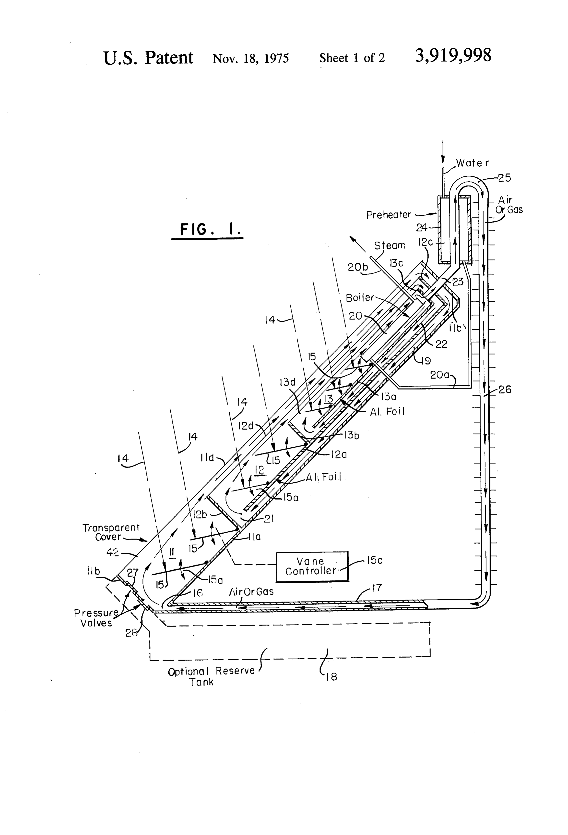
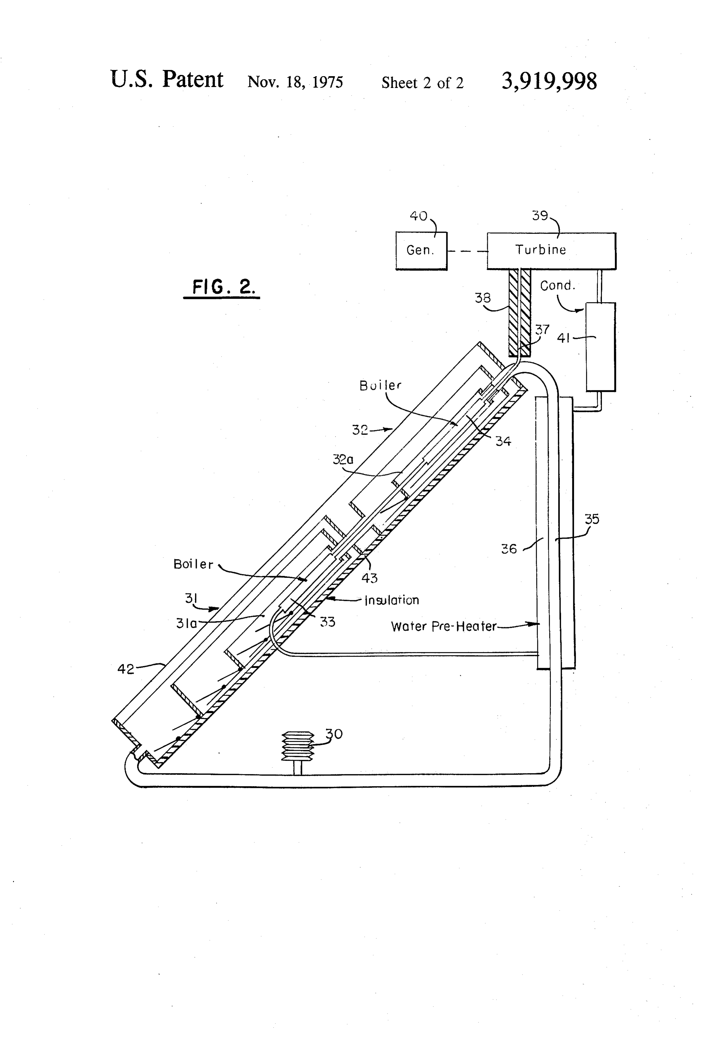
FIG. 1 is a cross-sectional diagrammatic view of a quently, solar heater constructed in accordance with the present 25 ers heat the entering hot air or gaseous medium deliv to the heat absorber and makes it impossible invention; and
Page 2drawing sheetscan →
Page 3drawing sheetscan →
Page 4scan →
material such as wood, plastic or the like, and each of
CONVECTION-TYPE soLAR HEATING UNIT which has one side thereof covered by a transparent el ement fabricated of glass, cellophane or the like, to
BACKGROUND OF THE INVENTION admit solar radiation to the interior of the containers. Various forms of solar heating arrangements have 5 The several containers are nested one within the other been suggested heretofore in an effort to use energy with their respective transparent covers being super from the sun as a source of heat. In its simplest form, posed and positioned to admit solar radiation to all of such an arrangement constitutes the judicious dispo the containers, and each container includes, on its inte sition and orientation of transparent surfaces arranged rior, one or more black body elements taking the form, to admit electromagnetic radiation emanating from the 10 for example, of a plurality of blackened vanes mounted Sun to an interior region which, preferably, includes an for movement within the container to permit appropri appropriate medium responsive to such radiation. The ate orientation of said vanes relative to the incoming medium typically employed heretofore has been water solar energy, whereby the black body elements within or a comparatively low boiling point liquid, which func 15 each container are heated by the incoming solar radia tions to absorb solar heat, and which is so arranged that tion. several nested containers are interconnected to the heat absorbed in the water or liquid can be ex oneTheanother by gas flow passageways which are so ar tracted therefrom for utilization as desired. Arrange ments of this type are described, for example, in the ranged that a gaseous medium is caused to flow by con U.S. Pats. to McHenry, No. 659,560, Baker, No. 20 vection continuously through said containers past the 695,136, Sherock, No. 3,250,269, Snelling, No. black body elements therein for heating by solar radia 3,390,672, Masters, No. 3,513,828, and Kyryluk, No. tion admitted through the transparent cover of each 3,514,942. container and by picking up additional heat from the In general, in arrangements of the type discussed black body elements within the container. More partic above, it has not been considered feasible to employ air ularly, each of the elongated nested containers includes or some other gas as the medium which is directly 25 a gas inlet at one end thereof and a gas outlet at its heated by solar radiation. In this respect, therefore, the other end, and the aforementioned gas flow passage present invention constitutes a departure from arrange ways connect the outlet of each container to the inlet of ments suggested heretofore in that it provides a solar the next inner one of said containers, and connect the heating structure which makes it feasible to use air or outlet from the innermost one of said containers to the some other gas as the medium to be heated by solar en 30 inlet of the outermost one of said containers, whereby ergy. the gaseous medium, e.g., air, carbon dioxide or the The overall efficiency of a solar heating system is like, flows continuously to and through each of the said measured by the heat units obtainable per unit of time nested containers in succession from the outermost container to the innermost container to cause said gas and per dollar invested instead, as is customary in other 35 eous types of energy conversion systems, by the ratio of heat medium to be heated to successively higher tem obtainable to useful heat received. Low efficiency cal peratures as it flows through said successive inwardly culated on this latter basis is quite permissible in a solar disposed containers. The innermost container includes heat utilization means which is responsive to the com heater due to the fact that a great abundance of low paratively level free energy is obtainable from the sun. In evaluat 40 high temperature heated gaseous medium ing the comparative efficiencies of solar heating sys flowing through the innermost container, and the heat tems, therefore, the most practical system thus be utilization means can comprise, for example, a boiler comes one that generates the greatest useful energy containing water which is converted to steam by the output per dollar invested. heated gaseous medium flowing through the innermost The present invention is accordingly further intended 45 container, or it can comprise one junction of a thermo to provide a solar heating system which has greater effi couple responsive to said heated gaseous medium for ciency than other solar heaters suggested heretofore, in generating electrical energy.
that it operates to concentrate electro-magnetic ratia An apparatus constructed in accordance with the tion emanating from the sun and derive practical bene present invention has been found to generate tempera fits from the concentrated energy in an arrangement 50 tures in the order of 250F at the innermost container. which makes use throughout of comparatively inexpen Since the air or other gaseous medium employed exhib sive components such as wood, plastic, or the like, its considerable expansion as its temperature is raised, without use of more expensive components which have and since the actual temperature achieved may vary often been utilized heretofore such as reflecting mir from minute to minute due to variations in incoming solar energy with a resultant almost constant variation rors or refractive media. The approved efficiency in this respect is achieved, moreover, by an arrangement 55 invided the pressure of the medium, the solar heater is pro with a mechanism, e.g., spring bias valves and/or which not only employs a gas as the medium heated by solar energy, but which effects movement of the gase an expansible bellows, which operates to eliminate any significant variation in the pressure of the flowing gase ous medium through the heater automatically by con ous medium and which keeps that pressure within the vection, thus permitting the elimination of mechanisms containers at a value substantially equal to the ambient such as a mechanically operated blower which would 60 pressure require additional energy for operation and which outside the containers, thereby eliminating the would, moreover, increase the cost of the solar heating need and consequent expense of containers fabricated unit. to resist the considerable gas pressures which would otherwise be produced.
SUMMARY OF THE INVENTION 65 To increase the efficiency of the overall system fur The solar heater of the present invention comprises a ther, plural groups of nested containers of the type de plurality of elongated containers each of which is fabri scribed can be connected in series with one another so cated of a comparatively inexpensive heat insulating that the flowing gaseous medium, after passing through 5 the containers of one group from the outermost to the The concept of placing several containers within one innermost container thereof, then passes to a further another has been used before, but it was found that the group of nested containers and flows from the outer outer containers in the prior arrangements do not de most to the innermost container of said further group liver heat to the innermost container, just insulate it. before being returned to the outermost container of the The reason for this is that the temperature of the air in first group. When the heat utilization means employed the outer containers is lower than in the innermost con in the innermost container takes the form of a steam tainer. Since heat travels from higher to lower tempera ture, it can only travel outward from the innermost boiler, moreover, the efficiency of the overall unit may container.
be further increased by extracting heat from the gase O ous medium emerging from the outlet of the innermost In contrast, the novel concept embodied in the pres container in a preheater which operates to raise the ent invention is that air or some other gaseous medium temperature of the water being supplied to the boiler. is first heated to a higher temperature than is in the in The output of the heater can be used in any well known nermost container, and then delivered to that con fashion and, when said output comprises steam, can be 15 tainer. This is accomplished by moving the gaseous me used for example to operate a steam turbine which in dium through several containers located within one an turn drives an electrical generator. other and heating it with black metal buffers exposed to solar radiation as will be described. After this, the
BRIEF DESCRIPTION OF THE DRAWINGS heated gaseous medium enters the innermost container The foregoing objects, advantages, construction and containing the heat absorbing element which is also ex operation of the present invention will become more posed ous to solar radiation. The temperature of the gase medium in this innermost container is somewhat readily apparent from the following description and ac companying drawings in which lower than the entering air temperature due to the steady removal of heat by the heat absorber 20. Conse
FIG. 1 is a cross-sectional diagrammatic view of a quently, solar heater constructed in accordance with the present 25 ers heat the entering hot air or gaseous medium deliv to the heat absorber and makes it impossible invention; and
FIG. 2 is a cross-sectional diagrammatic view of a for that absorber to lose heat it has received by direct radiation to the surrounding air by conduction. Be further embodiment of the invention employing series cause of the temperature gradient which exists from connected heating units of the type shown in FIG. 1. one to the next of the several boxes 11-13, the gaseous DESCRIPTION OF THE PREFERRED 30 medium can, through the provision of appropriate gas EMBODIMENTS flow passageway between the boxes, becaused to move automatically
FIG. 1 depicts a solar heater constructed in accor inner box 12 and from the outermost box 11 to the next dance with the present invention which consists of vection, with the gaseous then to the innermost box 13 by con three nested containers 11, 12 and 13 disposed one 35 cessively higher temperatures medium being heated to suc within the other and interconnected to one another for as it passes through said several boxes in succession.
the continual transfer of a gaseous medium from the Each of boxes 11-13 includes one or more black outermost container 11 to the innermost container 13 and thence back to the outermost container 11. While body elements provided to store heat energy from the three such containers are shown in FIG. 1, it will be ap 40 incoming solar radiation 14 so that, as the gaseous me dium passes said black body elements it picks up heat preciated that a different number of containers may be energy from said black body elements as well as from used in accordance with the present invention. Each radiant energy 14 itself. In the form shown in FIG. 1, container is, in cross section, of elongated rectangular configuration, but it will be further appreciated that the black body elements comprise a plurality of baffle plates 15 in each box, constructed for example of metal.
variations in the shapes of the containers may also be 45 having an appropriate black coating thereon, and made without departing from the principles of the pres mounted at their lower end for pivotal movement ent invention. In general, it is desirable that the con through arcs designated by arrows 15a to permit the tainers be fabricated of comparatively inexpensive ma several plates 15 in each box to be oriented in a direc terials exhibiting heat insulating properties such as the tion substantially at right angles to incoming solar radi materials earlier discussed, to minimize the cost of the SO ation 14. The orientation of the several plates 15 can be heater and thereby increase its efficiency from a solar adjusted by simple mechanical means, either by hand heating point of view. or by an appropriate vane controller 15b which is con The outermost container 11 comprises an opaque nected to the several plates or vanes 15 (only one such bottom wall 11a, a lower end wall 11b, an upper end vane has been shown interconnected to controller 15c wall 11c and a transparent cover 11d. The next inner 55 in FIG. 1 to simplify the drawing). The vane controller container 12 similarly comprises opaque bottom wall can comprise, for example, an appropriate clock mech 12a, lower end wall 12b, upper end wall 12c, and trans anism or other turning mechanism of known type. parent cover 12d; and the innermost container 13 simi The lower end of box 11 defines a gas inlet 16 for the larly comprises corresponding container portions admission of air (or an alternative gas such as carbon 13a-13a inclusive. The several transparent covers 11d, 60 dioxide) from conduit 17, or from an optional reserve 12d, and 13d are superposed in the fashion illustrated tank 18 (to be described). The gaseous medium enter to admit solar radiation 14 to each of the nested boxes ing box 11 at inlet 16 flows in an upward direction or containers 11-13. The object to be heated, which along the path indicated by the arrows in box 11, past comprises a boiler 20 in the form of the invention blackened plates 15 and thence through the region be shown in FIG. 1 (but which may comprise alternative 65 tween superposed transparent covers 11d, 12d to the heat utilization means such as the "hot' junction of a top of box 11. During this flow, the gaseous medium is thermocouple), is appropriately located or otherwise heated both by direct exposure to the sun's rays enter mounted within the innermost box 13. ing through cover 11d and by the adsorption of heat en 6 ergy from plates 15. After the gaseous medium reaches gas admission to enter or exit from the solar heater in the top of box 11, it proceeds out of the box through an dependence upon the comparative pressures inside and outlet located at the upper end of the box between outside of the heater. Valves of this type may be lo upper end walls 11c and 12c of boxes 11, 12 and then 5 cated at any appropriate place in the solar heater or gas passes through a channel 19 extending the length of flow lines, and such valves may be replaced by or sup box 12, and located between the opaque bottoms of plemented by other types of pressure compensating boxes 11, 12, to an inlet 21 at the lower end of box 12. means, e.g., a bellows adapted to expand or contract to The gaseous medium entering box 12 through said inlet compensate for corresponding volumetric changes in 21 then flows along a similar path in box 12, past the the gaseous medium. Such a bellows is shown at 30 in blackened plates 15therein and through the region be 10 the embodiment of FIG. 2.
tween transparent covers 12d, 13d to the back of box The use of air as the gaseous medium in the solar 12 whence it exits through an outlet defined between heater is optional and, if desired, a different gas having the upper end walls 12c, 13c, passes through a channel a higher specific heat, e.g., carbon dioxide, may be 22 extending the length of box 13 between bottoms 15 used instead. If this alternative arrangement is to be 12a, 13a at boxes 12, 13 enters box 13 through the inlet employed, the pressure valve 27, 28 should open to a at its lower end and then passes across plates 15 in box reserve gas tank. Such a tank has been designated, in 3 and around the exterior of boiler 20 to exit from box broken lines at 18 in FIG. 1. Carbon dioxide picks up 13 via outlet 23. The bottoms of boxes 12 and 13 are and carries heat to the boilers more efficiently than air, provided with aluminum foil coatings to prevent the air 20 but necessitates the use of an optional reserve tank which passes through channels 19 and 22 from receiv which, of course, increases the cost of the unit. ing heat from the inside of the boxes through their re The arrangement described in FIG. 1 accomplishes spective bottom walls. Due to the fact that the air is significant increase in the temperature of the gaseous flowing by convection, such heat transfer to channels medium by causing the same air orgas to circulate con 19 and 22 from the interiors of boxes 12 and 13 would tinuously from an outermost container to an inwardly tend to balance some of the convection current if the 25 disposed container and thence to a still further in air was heated as it passed through channels 19 and 22. wardly disposed container, with the air receiving addi Heat absorber 20 located within innermost box 13, tional increments of heat as it passes in succession over can take the form of a flat metal container, filled with the baffle plates of the successive different containers. water via a water inlet line 20a, and acting as a steam 30 However it will be appreciated that, while the solar ra boiler to produce steam at outlet line 20b. The heatab diation 14 passes through only a single transparent sorber or boiler 20 is preferably provided with a black cover to reach baffle plate 15 in container 11, it must ened surface, and also has a finned exterior to facilitate pass through two such transparent covers before reach absorption of heat from the gaseous medium flowing ing baffle plates in container 12, and through three past the exterior of the boiler20 (the fins are not shown 35 transparent covers before reaching the baffle plates in in the drawing for the sake of simplicity). The water container 13, and the provision of still further contain supplied to boiler inlet 20a may be taken from a pre ers in the nested arrangement would similarly increase heater 24 through which gas outlet line 25, connected the number of transparent covers or glass sheets to outlet 23 of box 13, is connected. The gaseous me through which radiant energy must pass. Inasmuch as dium flowing over boiler 20 loses some of its heat in 40 the light transmitting efficiency of glass is only about converting the water in boiler 20 to steam, and loses 90% each glass or transparent cover will decrease the additional heat in preheater 24 while simultaneously energy to which the baffle plates are subjected by about increasing the feed water temperature supplied to 10%. It will be appreciated, therefore, that the number boiler 20, thereby to effect a comparatively efficient of containers employed in nested relation to one an conversion of the heat in the flowing gaseous medium 45 other cannot be increased indefinitely since the law of to energy in the form of steam at outlet line 20b. diminishing returns applies.
The gaseous medium emerging from the outlet of in To overcome this limitation, a plurality of nested nermost box 13 is returned to inlet 16 of outermost box units of the general type shown in FIG. 1 can be con 11 by a finned conduit 26 which interconnects gas flow nected in series with one another with the heated gase lines 25 and 17 as illustrated. The fins on conduit 26 ous medium emerging from the innermost container of cool the gaseous medium flowing to line 17 thereby 50 one group of nested containers being supplied to the providing athermal head in the system and speeding up outermost container of a further group of similarly the convection process. The returning gaseous medium nested containers, etc. Such an arrangement is shown need not be cooled to ambient temperature, however, in FIG. 2.
and its temperature at the time it is supplied to inlet 16 The FIG.2 arrangement comprises two groups31, 32 of box 11 may be higher than that of the surrounding 55 of nested containers with each group being constructed air, resulting in a higher temperature ultimately at heat in accordance with the considerations already dis absorber 20 than would be the case if the return air cussed in reference to FIG. 1. The gaseous medium were cooled to ambient temperature. which eventually flows through innermost container Box 11, for example adjacent its lower end wall 11b, 60 31a of group 31 passes across the exterior of a boiler 33 is provided with a pair of spring bias pressure valves 27, and then 31a emerges from the outlet of said innermost 28 of the flap valve or other type, to maintain the pres container and passes to the inlet of the outermost sure within the solar heater at substantially ambient container in group 32. It thereafter passes through the pressure outside of the heater, thereby to compensate nested containers of group 32 in a fashion similar to for the significant pressure changes which would occur that described in reference to FIG. 1 eventually reach due to the heating of the gaseous medium flowing 65 ing innermost container 32a of group 32, passing across through the heater unit. This aspect of the invention the exterior of boiler 34 and emerging at the outlet of said innermost container 32a for passage through a re has been discussed earlier. The valves 27, 28 are nor turn line 35 back to the inlet of the outermost container mally closed and are oppositely poled to permit air or 7 of group 31. The air or gas movement through the other of each of said successively inwardly disposed nested containers of group 31 and thereafter through containers, and heat utilization means within the inner the nested containers of group 32 is effected entirely by most one of said containers responsive to the heated convection, and the heated air emerging from inner gaseous medium flowing through said innermost con most container 32a may, in a fashion similar to that de tainer.
scribed in reference to FIG. 1, pass through a water 2. The heater of claim 1 wherein said heat utilization preheater 36 which supplies water to boilers 33 and 34 means comprises receptacle means within the inner connected in series with one another. most one of said containers containing a quantity of liq The arrangement thus provided in FIG. 2 preheats uid which is heated by said flowing gaseous medium as the feed water in preheater 36, further heats the water 10 said medium flows through said innermost container. in boiler 33, and then supplies the feed water to boiler 3. The heater of claim 1 including pressure respon 34 where it is converted to steam which exits through sive valve means connected to said heater for maintain an outlet line 37 which is insulated as at 38. The steam ing the pressure of said gaseous medium substantially at thus generated may be used in any desired fashion, e.g., 5 a predetermined value as said medium is heated to suc it may be employed to operate a steam heated air con cessively higher temperatures.
ditioner of the type which presently uses a gas flame to 4. The solar heater of claim 1 wherein said gaseous generate the steam needed for its operation. medium is air which flows continuously to and through Alternatively, the steam in line 37 can be supplied to said nested containers successively by convection. utilization equipment such as a steam turbine 39 which 20 5. The solar heater of claim 1 including a tank con drives an electrical generator 40. When this latter type taining said gaseous medium, and valve means connect of utilization equipment is employed, the steam, after ing said tank to said heater to supply the gaseous me passing through turbine 39, can be fed to a condenser dium which flows through said heater. 41 which converts the steam to water and supplies it to 6. The solar heater of claim 5 wherein said gaseous preheater 36 for resupply to boilers 33 and 34. The ele 25 medium is carbon dioxide.
ments 39-41 should preferably be located at a position 7. The solar heater of claim 2 wherein said liquid is above the solar heating unit to permit the feed water to Water.
be supplied to the boilers in said unit by gravity, but the 8. The solar heater of claim 7 wherein said receptacle water supply may be pumped if such an arrangement is means comprises a boiler having a water inlet and a not convenient. steam outlet, and water supply means connected to said In the arrangement of FIG. 2, the various glass cover 30 water inlet, said water supply means including a water plates of the several nested containers are superposed preheater, the gas flow passageways connecting the by an additional glass plate 42 to provide extra protec outlet of the innermost one of said containers to the tion due to the fact that the entire solar heating unit is inlet of the outermost one of said containers passing normally located outside of the building or residence 35 through said preheater to preheat the water being sup with which it is associated and is subjected to various plied to said boiler inlet.
weather conditions. For the same reason, all of the ex 9. The solar heater of claim 1 wherein each of said terior surfaces of the solar heater are preferably cov containers includes an opaque bottom, said opaque ered by insulation such as that designated 43 in FIG. 2. bottoms being superposed, the gas flow passageway Similar considerations apply to the arrangement shown 40 connecting the outlet of each of said containers to the in F.G. 1. inlet of the next inner one of said containers extending While I have thus described preferred embodiments between the superposed bottoms of said containers. of the present invention, many variations will be appar bottom 10. The solar heater of claim 9 wherein the opaque ent to those skilled in the art and it must therefore be of said next inner one of said containers in understood that the foregoing description is intended 45 cludes a heat reflective surface operative to inhibit the to be illustrative only and not limitative of the present transfer of heat from each container to the gas flow invention. All such variations and modifications as are passageway below the bottom of that container. in accord with the principles described are meant to fall 11. The solar heater of claim 1 including black body within the scope of the appended claims. means in each of said containers exposed to said solar Having thus described my invention, I claim: radiation to be heated thereby and disposed in the path 1. A solar heater comprising a plurality of elongated 50 of gaseous medium flow through said container for containers nested one within the other, each of said heating said flowing medium.
containers having a transparent upper surface, the 12. The solar heater of claim 11 wherein said black transparent upper surfaces of said containers being su body means comprises a plurality of blackened vanes perposed and positioned to admit solar radiation to 55 mounted for pivotal movement within each of said con each of said containers, each of said containers includ tainers, and means for controlling the angular orienta ing an inlet adjacent one end thereof for a gaseous me tion of said vanes about their respective pivots relative dium to be heated within said container by solar radia to the direction of said solar radiation. tion, each of said containers also including an outlet for 13. The solar heater of claim 1 comprising plural the heated gaseous medium adjacent its other end, 60 groups of said nested containers, the inlets and outlets means defining a plurality of gas flow passageways con of the containers in each group being interconnected necting the outlet of each of said containers to the inlet by said gas flow passageways to cause said gaseous me of the next inner one of said containers and connecting dium to flow continuously from the outermost con the outlet of the innermost one of said containers to the tainer to the innermost container in each group, said inlet of the outermost one of said containers whereby 65 gas flow passageways also connecting said groups in se said gaseous medium flows continuously to and ries by connecting the outlet of the innermost container through each of said nested containers successively to in a first one of said groups to the inlet of the outermost cause said gaseous medium to be heated to successively container in a next one of said groups and connecting higher temperatures as it flows from one end to the the outlet of the innermost container of a group other 8 than said first group to the inlet of the outermost con 16. The solar heater of claim 15 wherein the boiler tainer of said first group, whereby said gaseous medium outlet of the second one of said groups is connected to is heated to successively higher temperatures as it flows a steam turbine and thence to a steam condenser the continuously from each container to the next inner outlet of which is connected to an inlet of one of said boilers, both the steam turbine and steam condenser container in each group and thence to another one of being said groups for further heating as it flows from one con located considerably higher than said boiler inlet tainer to the next inner container in said other group. to cause the condensate from said condenser to feed 14. The solar heater of claim 13 wherein the inner into the boiler by gravity.
most container of each group has a boiler therein con 10 17. The solar heater of claim 1 including at least one taining water, the boiler in each group having an outlet expansible bellows positioned to respond to the pres which is connected to an inlet of the boiler in the next sure of said flowing gaseous medium for controlling the one of said groups. pressure of said gaseous medium as it flows through 15. The solar heater of claim 14 wherein said plural said heater. sk xk xk k >k groups constitute two groups of said nested containers. 15
Provenance
- Collection
- Patents citing this work
- Pages
- 8
- Method
- pdftotext (the PDF's own text layer) + pdftoppm 300dpi page scans
- Patent office record
- patents.google.com →
- Source
- Google Patents citing-documents table
- Assignee
- Louis W Parker
- Published
- 1975-11-18
- Transcribed from
- patentimages.storage.googleapis.com →