

patent · US3927659A
Peak efficiency solar energy powered boiler and superheater
23 December 1975
Text
Page 1bibliographic recordscan →
United States Patent 19 Blake et al.
54 PEAK EFFICIENCY SOLAR ENERGY
POWERED BOLER AND SUPERHEATER
(75) Inventors: Floyd A. Blake, Littleton; Murlin T. Howerton, Denver, both of Colo.
(73) Assignee: Martin Marietta Corporation, New
York, N.Y.
(52) U.S. Cl.................................... 126/271; 60/641 (51) int. Cl................................................ F24j.3/02
UNITED STATES PATENTS
81 1274 lf l906 Carter................................. 26/27 1,696,003 l2/928 Harvey................................ 26/27 1951,403 3/1934 Goddard............................. 60/26 X 1969,839 8/1934 Goddard............................. 26/27 1993,213 3/1935 Gill..................................... 126/27 Primary Examiner-William F. O'Dea
Assistant Examiner-Peter D. Ferguson
Attorney, Agent, or Firm-Sughrue, Rothwell, Mion,
Zinn & Macpeak
A cup-shaped enclosure forms an energy conversion chamber open at one end to a solar energy radiation field which is generally in axial alignment therewith, the conversion field incorporating, in order, from the thermal energy receiver aperture at the open end, a boiler heat exchanger and a superheater heat ex changer, which line the radial wall and the closed end wall of the chamber respectively. A water cooled win dow at the aperture closes off the aperture end of the conversion chamber and is opaque to infra-red radia tion, prevents escape of thermal energy by convection. A frustoconical reflecting surface extends radially out ward of the enclosure and away from the window to reflect fringe solar radiation into the chamber. One or more cylindrical superheater heat exchanger coils may protrude axially towards the window from the rear end of the chamber. The frustoconical reflecting surface and the window are cooled by further heat exchangers which preheat the feed water entering the boiler heat exchanger.
7 Claims, 1 Drawing Figure
III
Drawings
Page 2drawing sheetscan →
Page 3scan →
conversion chamber which is axially aligned with a
PEAK EFFICIENCY SOLAR ENERGY POWERED solar energy radiation field and wherein a superheater BOLER AND SUPERHEATER heat exchanger extends across the closed end of the chamber and wherein the other end of the chamber is
BACKGROUND OF THE INVENTION open to the radiation field and forms a solar radiation FIELD OF THE INVENTION receiving aperture. A second tubular heat exchanger This invention relates to a boiler and superheater for lies within the enclosure and is positioned between the aperture and the superheater heat exchanger and ther the conversion of solar energy to thermal energy and mal insulation lies between the heat exchangers and the the creation of steam for powering a steam turbine 10 walls of the enclosure. The heat exchangers are fluid electric power plant or the like, and more particularly, coupled together and with means to supply water to the to an improved boiler and superheater which maximize first heat exchanger and remove superheated steam heat retention and improves the energy conversion from the second heat exchanger. The invention is di efficiency thereof. rected to the improvement wherein a light window 15 sealably overlies the aperture of the enclosure and is
Reference to related application
This application relates to U.S. application Ser. No. opaque to infra-red radiant energy and which absorbs some of the infra-red radiation and which is position 399,669 filed Sept. 21, 1973, and entitled “Direct Solar able in the focal plane of the concentrated solar radia Hydro-Electric Integrated System and Concentrating tion, and wherein means cool the window to prevent Heliostat for Same", and assigned to the common as 20 self destruction thereof. Escape of thermal energy by signee. convection is prevented with the energy conversion DESCRIPTION OF THE PRIOR ART efficiency of the boiler and superheater being en hanced.
Very few boiler superheater units employed in con A frustoconical reflecting surface or concentrator junction with a solar energy conversion system have 25 may surround the window and extend axially towards ever been successfully operated and these are on a the solar radiation field and is flared radially outward small laboratory scale. While attempts have been made from the window to reflect fringe solar energy into the to provide high efficiency in the conversion of the light chamber and through the light window. Preferably, energy of the solar field into thermal energy, and in means for cooling the frustoconical reflecting surface particular, with respect to the use of that thermal en 30 and the window itself comprise heat exchangers for ergy in the creation of steam and the superheating of preheating the boiler feed water.
the same, the known boiler and superheaters have been The chamber may include a cylindrical portion of an plagued by thermal convection losses as well as by loss enlarged diameter relative to the aperture which lies of fringe solar radiation due to optical system imperfec intermediate of a frontal frustoconical portion which tions, and loss through infra-red radiation as a result 35 flares radially outward from the window and a rearward arising from the temperature of the conversion surface. frustoconical portion which flares radially inward to While convection problems have been minimized to the superheater exchanger interface to maximize the some extent, by locating the boiler superheater unit effective surface area of the heat exchangers. A plural above the reflection mirror field with the cavity or ity of concentric cylindrical coils may protrude axially conversion chamber at the bottom of the unit and fac 40 from the rear wall of the chamber and form portions of ing vertically the mirror field, and while this trapped, to the superheater heat exchanger to increase the heat some extent, the hot air from convection in the cham exchanger surface area of the superheater without ber, this adversely limits the physical plant and results compromising the size of the boiler and super-heater only in minimizing to some degree convection losses. and without material shadowing solar energy impinge Additionally, where secondary concentration devices 45 ment on the boiler heat exchanger which concentri have been employed in the vicinity of the boiler and cally surrounds the superheater cylindrical coils. The superheater, these concentration devices have failed window may be formed of quartz and the superheater due to degradation caused by overheating in the atmo and boiler heat exchangers may be formed of stainless sphere. Further, it has been generally supposed that the 50 steel tubing.
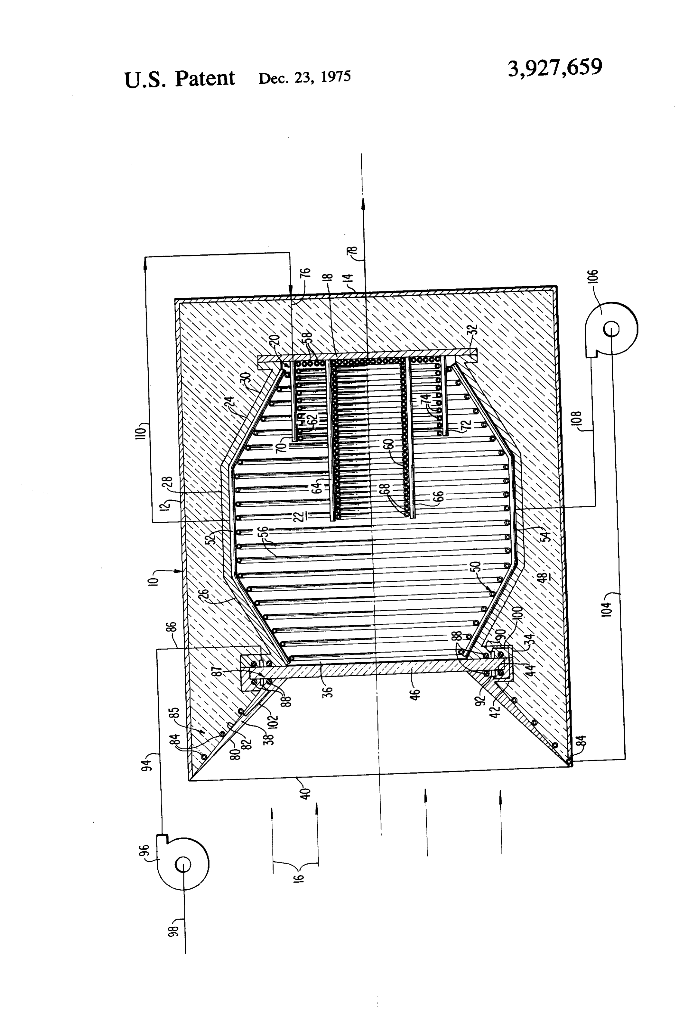
boiler superheater unit must be specifically designed BRIEF DESCRIPTION OF THE DRAWING for the flux field as provided by the particular reflection mirrors which supply the energy in concentrated form The single FIGURE is a partial schematic, sectional to the boiler superheater unit for conversion purposes, view of the improved peak efficiency solar energy pow and have thus limited entry into this field. ered boiler superheater of the present invention as 55 applied to a steam turbine energy conversion system.
Summary of the invention
Description of the preferred
The present invention is directed to an improved EMBODIMENT boiler and superheater with improved efficiency in the conversion of solar energy into thermal form, particu 60 Referring to the single FIGURE, there is illustrated larly with respect to a solar energy powered steam the peak efficiency solar energy powered boiler and turbine generator system in the multi-kilowatt size. The superheater 10 in section and which is incorporated improved boiler and superheater of the present inven within a steam turbine system driven and powered by tion permits this operation with dynamic or widely highly concentrated solar energy from a solar energy variable solar flux patterns, particularly as generated by source (not shown) but which directs a solar energy the concentrating heliostat of the above referred appli 65 field along a path coinciding with the axis of the boiler cation. and superheater 10. The boiler and superheater is tubu Such boiler and superheaters, include a tubular en lar and preferably cylindrical in configuration and is closure having one end closed and defining an energy formed of a metal enclosure or outer casing 12 which is 4 cup shaped in configuration including an end wall 14 while the superheated steam is removed from the su which closes off that end of the cylindrical casing 12 perheater heat exchanger at the center thereof by axial opposite to the radiant energy field indicated generally connection 78, which is fluid coupled to the inlet side by arrows 16. A bulkhead 18 spaced from end wall 14 of a steam turbine (not shown).
defines the position of a first or superheater heat ex With respect to the secondary concentrator 38, this changer 20 which lies at the rear of an energy conver member constitutes a formed frustoconical annulus, sion chamber or cavity 22 which is further defined by being provided with a reflective inner surface capable an inner tubular sheet metal member or casing 24. of withstanding moderately high temperatures in the Casing 24 consists of a frontal frustoconical section or atmosphere without loss of optical properties and may portion 26, an intermediate cylindrical portion 28 and O have a rhodium reflecting surface 80 and may be a rear frustoconical portion or section 30, the sections formed of a material such as brass or copper. Extreme being integral and the frustoconical portions 26 and 30 flaring radially outwards and radially inwards relative error rays from the reflection field 16 which are too low in concentration to warrant increasing the aperture size to the larger diameter cylindrical portion 28. The inner are reflected by reflecting surface 80 into the cavity casing 24 is provided with a flange 32 which sealably 15 aperture 36 and through the window 46, preferably the mates with bulkhead 18 at its rear edge, while it is reflective surface 80 should make an angle with the axis provided with a radially directed flange 34 at its for of the boiler superheater 10 of no greater than 45. ward end which defines a chamber solar energy receiv Otherwise, the angle is too great to reflect an apprecai ing aperture or opening 36 of a diameter considerably ble amount of the reflected radiation through window smaller than that of the external casing 12. Casing 12 20 46 and into the chamber or cavity 22. As reflection on extends axially beyond the inner casing 24 toward the large metallic surfaces with the highest reflectivity ma radiation field 16 and there is further provided a frusto terials such as silver and aluminum being less than 0.83, conical secondary concentrator 38 whose outer edge it is necessary to cool the concentrator 38 to avoid 40 is of a diameter approximating that of outer casing overheating and degradation or destruction of that 10 and whose inner end is flanged at 42. Flange 42 is 25 member. In this respect, on the radially outer surface further recessed at 44 so as to sealably interface with a 82 of the concentrator 38, there is provided a heat heat receiver window 46 formed of quartz, the quartz exchanger 85 comprising a series of loops of tubing 84 window 46 being opaque to infra-red radiation gener through which water for the boiler and superheater is ated within conversion chamber 22 but having little preheated prior to introduction into the heat exchang resistance to the transmission of light from the solar 30 ers 20 and 50 of chamber 22.
field 16 to the chamber 22. The flanges 42 and 34 are In order to hermetically seal the conversion chamber in edge abutment to sandwich the outer periphery of or cavity 22, annular grooves are provided in both window 46 therebetween. Thermal insulation 48 fills flanges 34 and 42 facing the sides of the quartz window the space between elements 38, 24, 18, and the outer 46 and conventional O-ring seals 80 fill these grooves casing 12. Means for fixing the secondary concentrator 35 and are compressed against the surfaces of the window. 38, the inner casing 24 and the bulkhead 18 are not Further, between each pair of the annular grooves and shown, but such are provided so as to minimize the the O-rings 88, there is provided annular grooves 90 conduction of heat between the inner and outer cas and 92 of rectangular configuration in cross section ings. The inner walls of chamber 22 are preferably within flanges 34 and 42 respectively, with the low black box, that is, non-radiant and positioned within pressure preheating inlet line 86 leading from the pre the chamber 22 and extending axially along the inner heater pump 96 supplying turbine condensate from a walls of casing sections 26, 38 and 30, is a boiler or condenser drain line 98 leading from the turbine (not second heat exchanger 50 which consists essentially of shown), thus causing the boiler feed water to be pre upper and lower tubular headers 52 and 54 forming heated while cooling window 46 seals 80 prevent leak parallel flow paths through the heat exchanger coils 56 45 age of coolant. A drilled passage 100 fluid connects the which are fluid coupled to the headers and extend annular grooves 90 and 92 which form heat exchanger between the same. The coils 56 are circular in configu 87, and a further drilled passage 102 fluid connects ration, when the chamber configuration is cylindrical. annular groove 92 within flange 42 to the concentrator In terms of the first superheater heat exchanger 20, heat exchanger 85 tubes 84, thus the boiler feed water preferably, this heat exchanger takes at least the form 50 is preheated by the heat exchanger associated with the of a coiled tube 58 mounted on the inner surface of window 46 and the concentrator or reflector 38. This bulkhead 18 and constituting the rear wall of chamber preheated water condensate is then fed from the loop 22, while further in the illustrated embodiment there is conduit 84 through preheater discharge line 104 to the shown inner and outer concentric, cylindrical super high pressure boiler feed water pump 106 where it heater coils 60 and 62 which project axially from the 55 discharges through boiler inlet line 108 into the lower chamber end wall defined by bulkhead 18 and for header 54 of the boiler heat exchanger 50. In turn, a wardly towards the window 46. The projecting coil 60 boiler steam discharge line 110 is fluid coupled to the includes upper and lower headers 64 and 66, fluid upper header 52 and directs the boiler steam to the coupled to and supporting circular tubing 68 in parallel superheater inlet line 76 which opens up into the upper flow paths, while the somewhat larger diameter pro 60 header 70 of axially protruding superheater coil 62. jecting cylindrical superheater coil 62 is provided with Series, parallcl, or series parallel flow connections are upper and lower headers 70 and 72 which support and made between the tubing 58 on the rear wall of the fluid couple closed loop heat exchange tubes 74. The chamber 22 and concentric protruding cylindrical coils end coil 58, and the headers of coils 60 and 62 may be 60 and 62 with the superheated steam being discharged fluid coupled to provide series, parallel or series paral 65 therefrom to the turbine. Thus, the improved boiler lel flow paths as desired. However, as illustrated, the and superheater of the present invention retains a max steam inlet connection to the superheater heat ex imum amount of the converted thermal energy with changer 20 is illustrated as being made to the header 76 little thermal loss while advantageously insuring that 5 the maximum energy of field 16 actually enters the thermal energy form, said boiler and superheater in conversion chamber 22. The employment of the heat cluding: a tubular enclosure having one end closed exchanger associated with window 46 and the reflector defining an energy conversion chamber and being axi or concentrator 30 provides a pre-heating phase for the 5 ally aligned with a solar energy radiation field, a first, boiler feed water which adds approximately 29% of the superheater heat exchanger extending across the cycle input energy. Boiler 50 adds approximately 50% closed end of said enclosure chamber, said other end of of the cycle input energy, and superheater 20 adds said chamber being open to said radiation field and approximately 15% of the cycle input energy to the forming a solar radiation receiving aperture, a second, steam passing through the turbine. The location of the tubular, boiler heat exchanger within said enclosure superheater heat exchanger at the rear of the heat 10 and positioned between said aperture and said super exchange cavity or chamber and concentric with the heater heat exchanger, thermal insulation between said boiler and further within the zone of maximum energy heat exchangers and the walls of said enclosure, means concentration intensity creates a natural fit with the fluid coupling said heat exchangers to permit fluid flow solar energy distribution pattern within the cavity, par from said second heat exchanger to said first heat ex ticularly as provided by concentrating heliostat of the 15 changer and means for supplying water to said second referred to application. The zone of high concentration heat exchanger and removing superheated steam from is also on the order of 15% of the total energy. The free said first heat exchanger, the improvement comprising: radiant energy from the walls of the superheater heat a light window in the form of a circular plate sealably exchanger 20 which operate 250 to 300 F. above the overlying said aperture of said enclosure chamber boiling temperature is absorbed by the surrounding and being opaque to infra-red radiant energy and boiler surface and constitutes a further efficiency im which absorbs some of said infra-red radiation and provement feature of the present invention. Further, being positionable in the focal plane of the concen the enlargement of chamber 22 in diameter relative to trated solar radiation, the diameter of the aperture 36 at the focal plane of the 25 a frustoconical reflecting surface surrounding said concentrated thermal solar radiation field 16 not only window, extending axially toward the solar radia increases the heat transfer area of the boiler, but pro tion field and being flared radially outward of said vides versatility to permit the boiler and superheater to window to reflect fringe solar energy into said operate with varied and dynamic flux patterns from chamber through said light window, different configurations of mirror field, and enables 30 annular duct means position at the circular plate varied steam production rates in areas of localized periphery for cooling said plate window to prevent energy concentration. Transverse diffusion of extreme self destruction thereof, said duct means compris concentrations is accomplished by internal metallic ing a third heat exchanger fluid coupled to said conduction and by the varied surface emissivity pat second heat exchanger and upstream thereof to ters. preheat the boiler feed water and a fourth heat As may be readily apparent from the description 35 exchanger fluid coupled to said second heat ex above, in operation, the cycle starts with water from changer and upstream thereof and mounted to said the condenser of the turbine (both not shown) being frusto conical reflecting surface to prevent its self pumped at low pressure by pump 96 through the pas destruction and to further preheat the boiler feed sages defined by tubing 84 and annular grooves 90 and 40 Water.
92 to cool the chamber window 46 and the secondary 2. The boiler and superheater as claimed in claim 1, concentrator 38. Upon leaving the preheating compo wherein said frustoconical reflecting surface has an nents, the water is raised to the cycle pressure by high angle no greater than 45 to the axis of said enclosure. pressure pump 106 and pumped into the boiler heat 3. The boiler and superheater as claimed in claim 1, exchanger 50. Steam and water separation occurs at 45 wherein said chamber includes at least a frustoconical the upper header 52 of the boiler heat exchanger 50 portion extending inwardly from said window toward and the steam exits the boiler heat exchanger and en said superheater heat exchanger and said second boiler ters the superheater heat exchanger 20. Superheater heat exchanger extends along said frustoconical cham heating takes place in the passages along the rear wall ber surface to effect enlargement of the effective sur as defined by tubing 58 and along the superheater heat 50 face area of at least said second heat exchanger. exchanger cylindrical protrusion coils 60 and 62 and is 4. The boiler and superheater as claimed in claim 1, discharged for use by the turbine at the center of the wherein said chamber includes a cylindrical portion chamber rear wall. While the low pressure tubing 84 intermediate of a frontal frustoconical portion which may comprise copper, upon pressurization by pump flares radially outwardly from said window and a rear 106, of necessity the boiler heat exchanger tubing and ward frustoconical portion which flares radially in the superheater heat exchanger tubing must be formed 55 wardly to the superheater heat exchanger interface to of stainless steel or the like capable of withstanding the maximize the effective surface area of the heat ex high temperature pressure combination necessary to changers.
the turbine operation desired, particularly with respect 5. The boiler and superheater as claimed in claim 4, for large size power plant operation. wherein said first superheater heat exchanger includes While the invention has been particularly shown and 60 at least one cylindrical coil portion which protrudes described with reference to a preferred embodiment axially from the rear wall of said chamber towards said thereof, it will be understood by those skilled in the art window to increase the heat exchange surface area of that various changes in form and details may be made the superheater heat exchanger and being of a diameter therein without departing from the spirit and scope of 65 somewhat less than the diameter of the second heat the invention. exchanger and being concentrically positioned relative What is claimed is: to said second heat exchanger to effectively increase 1. In a solar energy powered steam boiler and super the heat exchange surface of the superheater heat ex heater for converting concentrated solar radiation to changer due to the low film coefficient of heat transfer 6 in the superheater heat exchanger to the gaseous steam and being concentrically positioned relative to said carried thereby. second heat exchanger to effectively increase the heat 6. The boiler and superheater as claimed in claim 1, exchange surface of the superheater heat exchanger wherein said first superheater heat exchanger includes due to the low film coefficient of heat transfer in the at least one cylindrical coil portion which protrudes superheater heat exchanger to the gaseous steam car axially from the rear wall of said chamber towards said ried thereby.
window to increase the heat exchange surface area of 7. The boiler and superheater as claimed in claim 1, the superheater heat exchanger and being of a diameter wherein said windowk is kformed ofk quartz. less than the diameter of the second heat exchanger 10 s xk
Provenance
- Collection
- Patents citing this work
- Pages
- 6
- Method
- pdftotext (the PDF's own text layer) + pdftoppm 300dpi page scans
- Patent office record
- patents.google.com →
- Source
- Google Patents citing-documents table
- Assignee
- Martin Marietta Corp
- Published
- 1975-12-23
- Transcribed from
- patentimages.storage.googleapis.com →