

patent · US3983882A
Method and apparatus for hydrogen fueled internal combustion engines
5 October 1976
Text
Page 1scan →
United States Patent (19)
Billings
54 method and apparatus for
Hydrogen fueled internal
Combuston engines
(75) Inventor: Roger Evan Billings, Provo, Utah 73) Assignee: Billings Energy Research
Corporation, Provo, Utah
Related U.S. Application Data
52 U.S. Cl............................... 123/1 A; 123/25 A;
United states patents
1,268,648 6/1918 Van Meter............................ 137162 3,608,529 9/1971 Smith et al............... 123/DIG. 12 X 3,616,779 1 1/1971 Newkirk ......................... 1231120 X
3,672,341 6/1972 Smith et al............... 123/DIG. 12 X 3,682, 142 8/1972 Newkirk............................. 12311 A 3,696,795. 10/1972 Smith et al.......................... 12311 A 3,710,770 111973 Newkirk et al..................... 123/120
Condenser
(PREcooLER).
Other publications
“The UCLA Hydrogen Car' by A. F. Bush and W. D.
Van Vorst, Paper Presented at Cryogenic Conference Aug. 8-10, 1973, from Advances in Cryogenic
Engineering.
Primary Examiner-Charles J. Myhre
Assistant Examiner-Tony M. Argenbright
Attorney, Agent, or Firm-Criddle, Thorpe & Western
The hydrogen engine hereof introduces water as vapor with inlet hydrogen and air, as a mixture proportioned for practical internal combustion and efficient power output. Water vapor is a substantial component of the exhaust of hydrogen fueled engines. In one embodi ment of the invention, water vapor is condensed from the exhaust, and thereupon arranged to provide the input water as a continuing self-supporting process. The resultant emissions are very low in oxides of nitro gen, and readily meet the EPA Standards on pollut ants as presently set for 1976. Further, and impor tantly, engine backfire is eliminated in the operation. Also, engine output power and efficiency are im proved with the invention principles.
32 Claims, 6 Drawing Figures
(final)
Reservor
(water)
Drawings
Page 2drawing sheetscan →
Page 3drawing sheetscan →
Page 4scan →
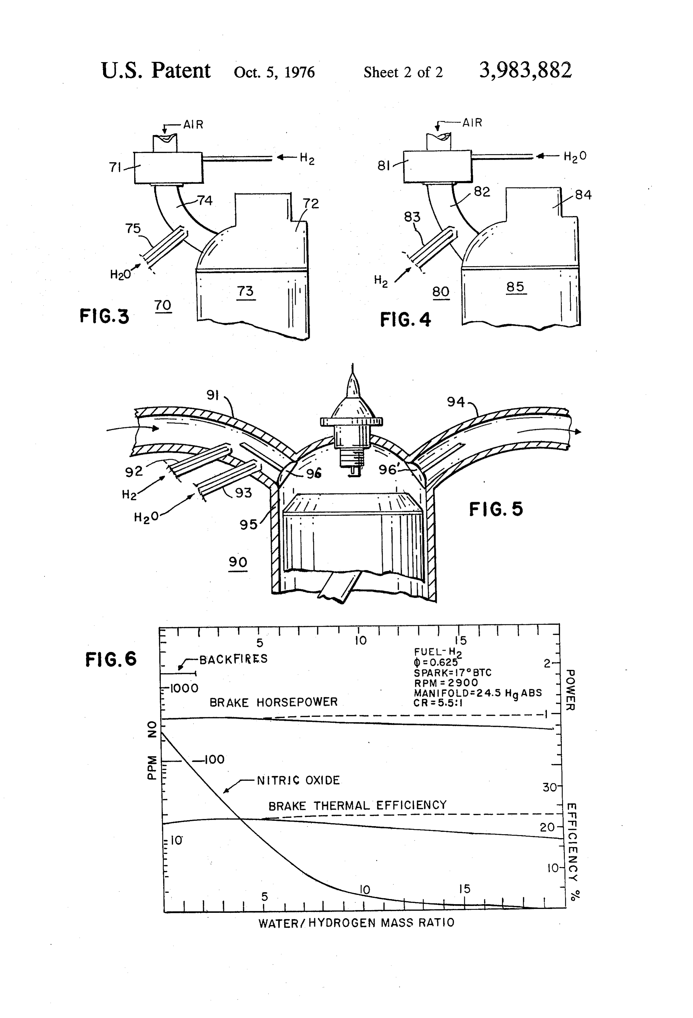
FIGS. 3, 4 and 5 show modified forms of the inven
METHOD AND APPARATUS FOR HYDROGEN tion system.
FUELED INTERNAL COMBUSTON ENGINES FIG. 6 is a set of curves that illustrate performance of BACKGROUND OF THE INVENTION the engine system upon variation of the ratio of water induction.
This is a continuation of application Ser. No.
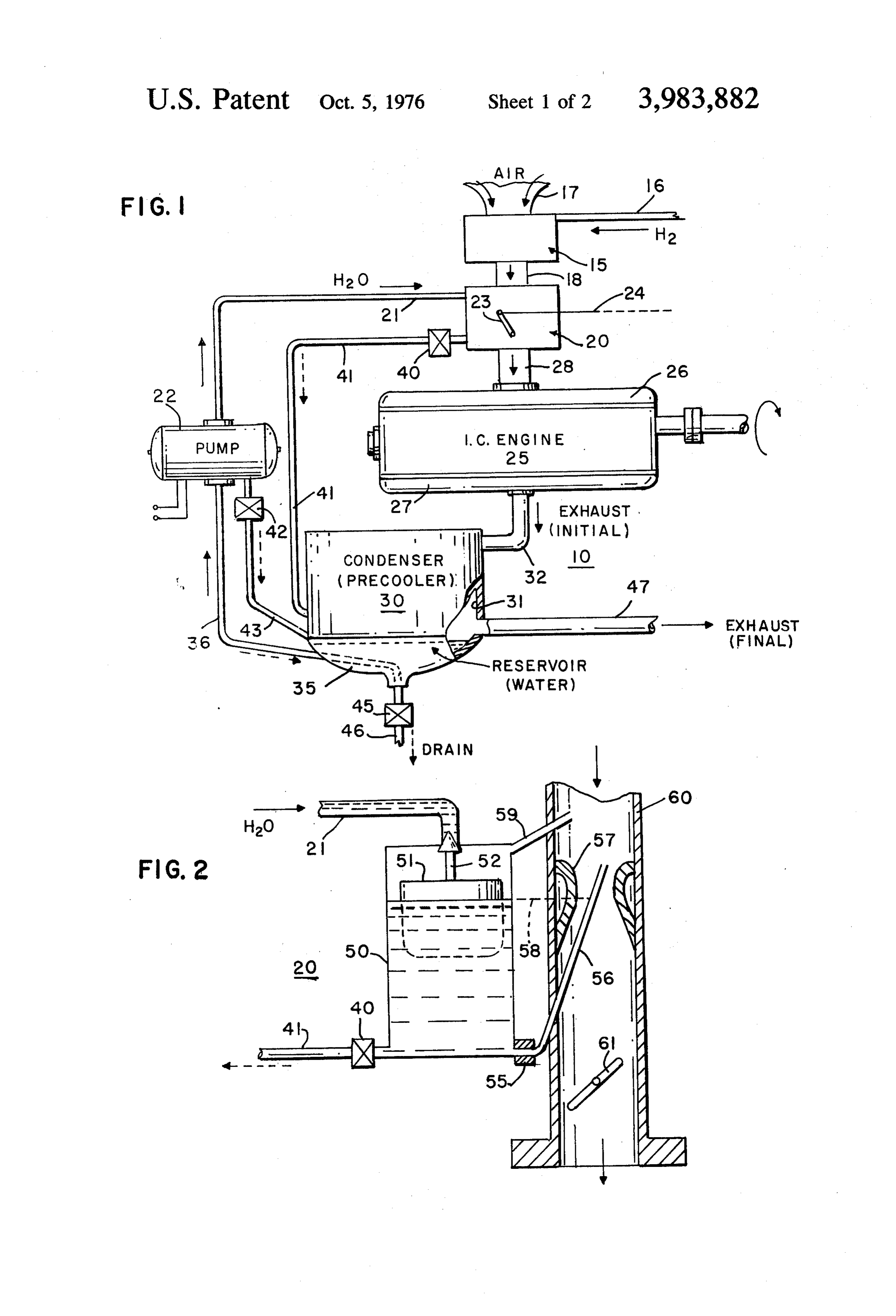
385,439, filed Aug. 3, 1973. DESCRIPTION OF THE INVENTION Water introduction has been proposed for gasoline The engine system 10 of FIG. 1 utilizes two carbure internal combustion engine (ICE) systems to moderate tors 15 and 20 in series flow relation. Carburetor 15 is peak cycle temperature, and thereby reduce formation 10 for the hydrogen (H,) input via supply line 16. Line 16 of oxides of nitrogen (NOx). However, the water vapor is supplied with gaseous H at relatively low pressure; increased the emission of carbon monoxide (CO) and can be reduced from a tank at high pressure. Air input hydrocarbons (HC) in the exhaust. The resultant pol duct 17 leads into the carburetor 15. The air is mixed in lutants of such gasoline fueled engine thus were poor. preset proportion with the hydrogen, in conventional One approach to hydrogen ICE systems utilizes the 15 ae.
recirculation of exhaust products back as a substantial A commercially available carburetor for unit 15 is an portion of the input charge, as taken directly from the air/gas valve diaphragm-operated type, as made by exhaust. Nevertheless no significant reduction in NOx Impco. The Hfair mixture from carburetor 15 is di formation occurs until excess oxygen in the cylinders is rected into water carburetor 20 viaduct 18. Carburetor almost completely displaced by exhaust gases but this 20 20 may be a usual gasoline type, serving as the water reduces output power and efficiency. (HO) metering device. FIG. 2 is a schematic showing SUMMARY OF THE INVENTION of carburetor 20 hereof, and is described later on. The carburetors 15 and 20 are readily adapted for the hy
The hydrogen fueled ICE system hereof utilizes di drogen and for the water flow respectively, by making rect water induction to provide improved operation. 25 their jet nozzles of suitable size, or adjusting their me Conventional ICE engine structures and tooling are tering as indicated.
used. Although water from any source could be used, in Condensed water is directed into carburetor 20 via accordance with one embodiment of the invention, supply line 21 by pump 22. The predetermined mass water vapor formed during the hydrogen/air combus ratio of water vapor to hydrogen is substantially main tion process, together with that introduced through the 30 tained by the settings in carburetor 20. The overall air input, are withdrawn and condensed for reintroduction proportion with respect to both the H, and H2O is also into the system. A reservoir maintains a water level maintained by the carburetors 15,20 over the engine ample for the induction operation. Sufficient water is power operating range, as will now be understood by produced to maintain predetermined vapor input. No those skilled in the art. The pivoted throttle valve compromise as to HC or CO generation is required as 35 therein is controlled by lever 23 and wire 24. The mix in gasoline and liquified gas systems, as neither is gen ture of air, H and HO-vapor in the quantity or volume erated in hydrogen combustion. as determined by the throttle setting, is conducted into The formation of NO is significantly reduced over the intake manifold 26 of engine 25 through inlet 28. It prior hydrogen ICE systems by maintaining an opti is to be understood that the physical positions of carbu mum range of the mass ratio of input water to hydro 40 retors 15 and 20 may be reversed in system 10, with the gen, as will be set forth. Backfiring to the intake mani same results.
fold is eliminated as a problem in the hydrogen fueled The initial engine exhaust is introduced directly to system hereof. The input water vapor quenches the condenser 30 by tubing 32 from the exhaust manifold hydrogen combustion process, thereby slowing down 27. The condenser 30 serves as a precooler, and acts to the hydrogen combustion rate, and thus potential back 45 muffle sounds from the engine. The interior surface of firing. the walls 31 of condenser 30 are proportioned to con Water from the maintained reservoir is pumped to an dense out and convert contained water vapor into suffi injector nozzle or carburetor, and in turn admixed with cient water for the peak demands of the engine/vehicle. the input hydrogen to the cylinders. A static water The water enters the reservoir 35 thereof, and is re storage tank is unneeded but could by employed if 50 tained for the induction to the engine. A feed line 36 desired. Thermostatically controlled drains automati extends from an opening in the lower region of reser cally empty water-using components to prevent their voir 35 to the input of the water pump 22. The pump 22 freezing-up when the engine is out of use. Antifreeze is creates a forward pressure on water line 36 and into not required. Sufficient water becomes available water supply line 21 to carburetor 20. Pump 22 may be promptly upon engine startup. Water replenishment or 55 electrically driven, or be a mechanical one. The pump storage are thus obviated. The terms "water vapor' input can back drain via line 36.
and "vapor' are used to mean: (a) the vapor of water; For a 50 brake horsepower (BHP) vehicle, such as a (b) water mist; (c) water spray; (d) water droplets; (e) small Volkswagen, up to 12 gallons of inducted water or any equivalent or combination thereof. may be used per hour of operation. A 12 volt, one 60 ampere motor for the pump 22 would be satisfactory
The drawings
therefor, Cars with larger engines would require pro
FIG. 1 is a diagrammatic representation of an exem portionally higher water flow rates at rated power, and plary form of the hydrogen fueled engine system in correspondingly larger pumps. The condenser 30 sys accordance with the present invention. tem is designed to condense out water at a sufficient FIG. 2 is a schematic showing, in cross-section, of a 65 rate to serve under all steady-state drive conditions. carburetor for converting water to inlet vapor and mix The reservoir 35 is included to store enough water to at ing it in predetermined mass ratio to the hydrogen as least handle rapid transient drive demands, such as used. passing another car at high speed. About one-half a 5 liter of water for such spurts is sufficient reserve for a to the cylinders in head 84 of engine 85. System 80 is 50 BHP vehicle, and proportionately more for larger the inverse of system 70 as to carburetion/injection cars. Residual gases and water vapor from the exhaust approach for the H/HO. Another system is 90 of FIG. within condenser 30, together with excess condensed 5. The intake manifold 91 directs air towards the intake water or overflow from reservoir 35, exit through "fi valve(s) 96. The hydrogen and the water both are sepa nal' exhaust pipe 47, the tail pipe. rately injected into intake manifold 91 through respec An important feature of the invention engine system tive injector nozzles 92,93. A predetermined ratio of is to automatically prevent water freeze-up in the com air, H and HO-vapor enters the cylinder(s) 95 when ponents of the induction water sub-system 20,22,35 their respective intake valve(s) 96 are open. The com during engine non-use in cold conditions. Towards this O bustion by-products from cylinder(s) 95 exist through end a thermostatically controlled valve is placed at a the exhaust manifold 94 after exhaust valve(s) 96 are drain port of water carburetor 20, at the chamber drain successively opened into it.
of pump 22, and at the base of the reservoir 35. Ther Engine system 10 per FIG. with series carburetion mal valve 40 at the base of carburetor 20 communi of the H and HO is simpler and lower in cost than the cates to condenser 30 via tubing 41. Thermal valve 42 15 systems of FIGS. 3, 4 and 5. The injectors of the latter at pump 22 also is drained into condenser 30 via tubing system may be mechanical devices known in the art. 43. Thermostatically controlled valve 45 drains the Also, electronic injectors may be used, such as manu reservoir 35 through exit piping 46. The thermostatic factured by the Robert Bosch company of Stuttgart, controls 40,42,45 are preset to actuate their respective Germany. Further, as stated, the physical order of the valves to “open' to effect their drain function at and 20 H, and HO induction and/or injection is optional. The below a predetermined temperature. The preset tem term “induction' is used to mean that mixing is accom perature depends upon respective location in the en plished by the fluid dynamics of the intake system, as gine compartment, and somewhat empirical determina by vacuum, venturi, orifices, and the like. The term tion with respect to ambient temperature and wind "injection' is used to mean that the input is forced velocity at the vehicle for the water to freeze. Settings 25 directly through an injector nozzle, as by a pump. "In in the range of 32° F to even 40 are thus in order, a troduction' is used herein as a generic term with re “safe" one being 35 F. spect to “induction' and "injection', or other manner ln any event, when the engine is in operation the of presenting gaseous hydrogen and/or water vapor to compartment temperature is much above the 35 F the engine intake in its operation.
mark, and the valves remain “closed' even during 30 The condenser, as 30 in FIG. 1, may be an "open sub-freezing wintry weather. The water condensation box' type as indicated. Its internal walls 31 serve as the and induction process thereupon proceeds. During condensing structure. Walls 31 are exposed internally engine startup with the water drained, the engine to the hot vapor-laden exhaust. The exterior of the warms up rapidly and triggers these temperature set walls are exposed to the ambient temperature in the valves to "closed". Further, the startup exhaust con 35 engine compartment region cooling them, and thus the tains sufficient water vapor to be condensed in 30, gases and vapor inside. For a small (50 BHP) vehicle, pumped by 22, carbureted at 20, and amply be in about 2.5 square feet of internal wall 31 surface will ducted to engine 25 with the hydrogen. In fact, the continuously condense-out sufficient water for the en reservoir 35 soon fills up as well. gine systems hereof. The surface required is generally An exemplary water carburetor 20 is illustrated in 40 linear with BHP requirement. Thus a 100 BHP car FIG. 2. It is basically like a gasoline type. The water would use about 5 square feet therefor. A "collection supply line 21 ends at a needle valve at the upper part chamber' as within unit 30, is preferably included of receiving chamber 50. When sufficient water is in wherein the dynamic pressure (PV) is less* than four chamber 50 the float 51 closes needle valve 52. A so that water droplets will precipitate from the exhaust metering orifice or jet 55 is at the base of chamber 50. 45 stream rather than for the most part be blown out It proportions the flow of water into tube 56 that ex through the tail pipe 47. The condenser 30 configura tends to the throat of venturi 57, and is above the water tion and size may be optimized in well known manner: level 58. A vent line 59 extends from chamber 50 into as by corrugation of the walls; by interior finned tubing mixing chamber 60. Throttle valve 61 is positioned in as through which an engine cooling medium passes;
FIGS. 3 and 4 show modified versions of the exem * in English units plary engine system 10 of FIG. 1. System 70 of FIG. 3 As hereinabove stated, the water induction system is the same as system 10 except that jet nozzle injection hereof, unlike exhaust recirculation, has positive ad of water is used in place of carburetion. The hydrogen vantages both on emissions and on performance. Refer (H,) is carbureted by unit 71 and ducted to the cylinder 55 ence is made to the test curves of FIG. 6. The control head 72 of engine 73, by tube 74. An injector nozzle 75 variable thereof is the mass ratio of water to hydrogen is arranged to enter into pipe 74. Water (HO) is in in the intake of the invention systems. At very low jected into duct 74 in measured amount through nozzle water injection or induction, as at the order of a one-to 75, in known manner. The resultant water spray mixes one mass ratio, the test hydrogen fueled engine gener with carbureted hydrogen, and is passed to the intake 60 ated over 100 PPM of nitric oxide (NO). The logarith manifold in cylinder head 72. The mass ratio of the mic scale for NO shows the order of 10 PPM of NO water to hydrogen in the combined mixture (with air) is when the mass ratio of HO/H is five (5). It is noted predetermined as set forth hereinafter, for optimum that backfiring thereof ceases at mass ratios above two results. (2). In fact, as the mass ratio is increased, the NO FIG. 4 shows an engine system 80 wherein the water 65 generated rapidly falls off towards zero at a ratio of is carbureted at 81, and the hydrogen is injected into 15:1.
common duct 82 by injector nozzle 83. The combined The power output and thermal efficiency are im air, H, and HO-vapor mixture is conveyed by duct 82 proved by 4% at an HO/H, ratio of 3.5:1, while NO 6 was reduced 90%. With the water to hydrogen ratio 5. An internal combustion engine as in claim 4, in increased to 5:1 the engine may be operated with full which said metering device maintains the mass ratio of stoichiometric mixtures, thus operating at its maximum water to hydrogen at the engine intake in the order of power without backfiring. This is a particularly impor 2:1 or greater.
tant result for the conversion of gasoline to H, powered 6. An internal combustion engine as in claim 3, in automobiles. They can be operated at leaner more which said first and second carburetor means are ad efficient mixtures for cruising conditions and employ justed to maintain the mass ratio of the water to hydro richer full-throttle hydrogen metering to obtain bursts gen at the engine intake in the order of 2:1 or greater. of power during acceleration without backfiring. 7. An internal combustion engine as in claim 2, in The test ICE engine used to derive the curves of FIG. O which said second means is a device for injecting water 6 using water introduction had the following physical droplets, spray or mist in predetermined ratio amount parameters with iso-octane (Standard gasoline): over the engine operating range. 8. An internal combustion engine as in claim 7, in (a) Peak Power = .73 BHP at db' = 1.16 15 which said second means injects water vapor at a rate (b) Max. BTE = 21.5% at d' = 0.93 to maintain the mass ratio of water to hydrogen at the (c) Max. NO = 800 PPM at db' = 0.93 engine intake in the order of 2:1 or greater. For Fig 6: d is the hydrogen-air equivalence ratio; 9. An internal combustion engine as in claim 1, in the fraction of hydrogen used relative which said first means is a device for injecting hydrogen to the chemically correct quantity for 20 gas in predetermined ratio over the engine operating
BHP is brake horsepower
Also:
BTC is brake thermal efficiency is the spark advance position "before 10. An internal combustion engine as in claim 9, in top center'. which said second means is a carburetor that produces CR is compression ratio. water droplets, spray or mist from input water and is 25 adjusted to supply the intake water in a predetermined mass ratio proportion to the intake hydrogen generally
A simulation of the aforesaid technique on the test over the engine operating range.
engine resulted in 1.28 BHP or 74% of the maximum 11. An internal combustion engine as in claim.9, in power obtainable by the engine operating on gasoline. which said second means is a device for injecting water This result is considered to be very competitive with 30 droplets, spray or mist in predetermined mass ratio the actual output of modern gasoline engines which are amount to the injected hydrogen. tuned for minimum emissions rather than maximum 12. An internal combustion engine as in claim 1, power. With use of rich mixtures of hydrogen fuel and which said first and second means are adjusted to main water induction in the 50 BHP Volkswagen referred to, 35 tain the mass ratio of the water to hydrogen at the the acceleration available was quite comparable to that engine intake in the order of 2:1 or greater. of the car when fueled with gasoline. 13. An internal combustion engine as in claim 1, in What is claimed is: which said condensing means comprises a reservoir for 1. An internal combustion engine having an engine collecting condensed water, said reservoir including an fuel intake and one or more cylinders in which fuel 40 opening therein, and in which said water supplying combustion occurs, said engine including first means means is connected to said reservoir for receiving water for introducing gaseous hydrogen and air in metered through said opening.
relation to the engine intake for sequential combustion 14. An internal combustion engine as in claim 13, in in the cylinders, second means for producing water which said condensing means further comprises walls droplets, spray or mist from supplied liquid water and 45 defining a chamber above said reservoir for condensing for introducing said water droplets, spray or mist to water vapor introduced thereinto, means for introduc said intake in conjunction with the hydrogen and air, ing the exhaust of the hydrogen combustion process means for condensing exiting resultant water vapor of into said chamber, and means for conducting from said the hydrogen combustion process, and means for sup chamber the exhaust products remaining after conden plying the condensed water to said second means in 50 Sat10.
such proportion whereby the engine is supplied with 15. An internal combustion engine as in claim 1, hydrogen, water and air at its intake to inhibit backfir further including draining means for draining water ing in its operation. from the condensing means to prevent freeze-up of 2. An internal combustion engine as in claim 1, in water therein while the engine is out of use during which said first means is a carburetor that is adjusted to 55 freezing weather conditions. supply the intake hydrogen with intake air. 16. An internal combustion engine as in claim 15, 3. An internal combustion engine as in claim 2, in further including a second draining means for draining which said second means is a carburetor positioned in water out of said second means to prevent freeze-up of series flow relation to said first means carburetor for water therein.
producing water droplets, spray or mist from input 60 17. An internal combustion engine as in claim 16, water and being adjustable to supply the intake water in further including third draining means for draining a predetermined mass ratio proportion to the intake water out of said water supplying means to prevent hydrogen generally over the engine operating range. freeze-up of water therein. 4. An internal combustion engine as in claim 3, in 18. An internal combustion engine as in claim 17, which said second carburetor means includes a meter 65 further including means for conveying water from said ing device that in general maintains the mass ratio of second draining means to said condensing means, and the water to hydrogen at the engine intake at a prede means for conveying water from said third draining termined level. means to said condensing means.
Page 7scan →
19. An internal combustion engine as in claim 15, in maintain the mass ratio of the water to hydrogen in the which said draining means is thermostatically con order of 2:1 or greater.
trolled and includes a valve. 26. An internal combustion engine as in claim 20 20. In an internal combustion engine having an en further including draining means for draining water gine fuel intake, one or more chambers in which fuel from said water reservoir to prevent freeze-up of water combustion occurs, and structure for introducing air therein during freezing conditions. into the engine intake, the improvement comprising 27. An internal combustion engine as in claim 26 first means for introducing gaseous hydrogen into the further including draining means for draining water air introducing structure for combustion in the O from said second means into said water reservoir and chambers, from said water conveying means into said reservoir to second means for producing finely divided water, prevent freeze-up of water in the second means and in including droplets, spray or mist, from input water the water conveying means during freezing weather and for introducing the finely divided water into conditions.
the air introducing structure in conjunction with 15 28. An internal combustion engine as in claim 20 the hydrogen, further including means for condensing water vapor a reservoir for holding water, and contained in the exhaust from the hydrogen combus means for conveying water from said water reservoir tion process and for depositing such condensed water to said second means, in said water reservoir.
said first and second means being adapted to supply 20 29. An internal combustion engine as in claim 28 the intake hydrogen and intake water in such pro further including means for removing from the con portion as to inhibit backfiring. densing means exhaust products remaining after con 21. An internal combustion engine as in claim 20 densation.
wherein said first means comprises a carburetor and 30. A method of inhibiting backfiring in a hydrogen said second means comprises a carburetor in series 25 fueled internal combustion engine comprising relation with the first carburetor means, said second a. introducing gaseous hydrogen and air in metered carburetor means being adapted to produce finely di relation to the engine intake for combustion in the vided water from input water. cylinders, 22. An internal combustion engine as in claim 20 b. storing water, wherein said first means comprises a carburetor and 30 c. producing liquid water droplets, spray or mist from said second means comprises a device for injecting the stored water, and finely divided water into the air introducing structure. d. applying the droplets, spray or mist to the engine 23. An internal combustion engine as in claim 20 intake for admixing with the hydrogen in a prede wherein said first means is a device for injecting hydro termined mass ratio sufficient to inhibit backfiring. gen gas into the air introducing structure and said sec 35 31. A method as in claim 30 wherein step (b) com ond means comprises a carburetor adapted to produce prises finely divided water from input water. f. condensing water vapor contained in the exhaust 24. An internal combustion engine as in claim 20 from the hydrogen combustion process, and wherein said first means comprises a device for inject g, depositing the condensed water in a storage reser ing hydrogen gas into the air introducing structure and 40 voir.
said second means comprises a device for injecting 32. A method as in claim 30 wherein water is ad finely divided water into the air introducing structure. mixed with hydrogen in a mass ratio of water to hydro 25. An internal combustion engine as in claim 20 gen in the order of 2:1 kor greater.k wherein said first and second means are adapted to
Provenance
- Collection
- Patents citing this work
- Pages
- 7
- Method
- pdftotext (the PDF's own text layer) + pdftoppm 300dpi page scans
- Patent office record
- patents.google.com →
- Source
- Google Patents citing-documents table
- Assignee
- Billings Energy Research Corporation
- Published
- 1976-10-05
- Transcribed from
- patentimages.storage.googleapis.com →