

patent · US4002160A
Solar energy collection system
11 January 1977
Text
Page 1bibliographic recordscan →
Mather, Jr.
54). SOLAR ENERGY COLLECTION SYSTEM
75 Inventor: George R. Mather, Jr., Toledo, Ohio Assignee: Owens-Illinois, Inc., Toledo, Ohio
(5ll int. Cl”............................................ F24, 3/02
UNITED STATES PATENTS
980,505 1119 Emmet .............................. 126/271 2,213,894 9/1940 Barry ................................. 126/271 3,390,672 7|1968 Snelling ............................. 1261271
FOREIGN PATENTS OR APPLICATIONS
1,243,22 4/1960 France ............................... 1261271
Primary Examiner-Kenneth W. Sprague
Assistant Examiner-James C. Yeung
Attorney, Agent, or Firm-Steve M. McLary; E. J. Holler
A multiple tube solar energy collector having a diffuse ly-reflecting surface positioned behind the collector tube array. Multiple double walled collector tubes are connected into a manifold for circulation of a Working fluid through them. The working fluid is heated by Solar energy as it flows through the tubes. A diffusely-reflect ing surface behind the tubes reflects back to the tubes both direct beam and diffuse solar radiation which fails to strike the tubes directly. This system allows efficient operation of a tubular solar energy collector without requiring focusing or polished reflecting surfaces. The tubes are preferably no more than four tube diameters apart, on centers, and no more than four tube diame ters above or separated from the diffuse-reflecting sur face.
7 Claims, 4 Drawing Figures
Drawings
Page 2drawing sheetscan →
Page 3drawing sheetscan →
Page 4drawing sheetscan →
Page 5scan →
shown at an angle of about 60 from the horizontal. An
SOLAR ENERGY COLLECTION SYSTEM additional component of the total solar energy avail able is a diffuse-radiation component designated as St.
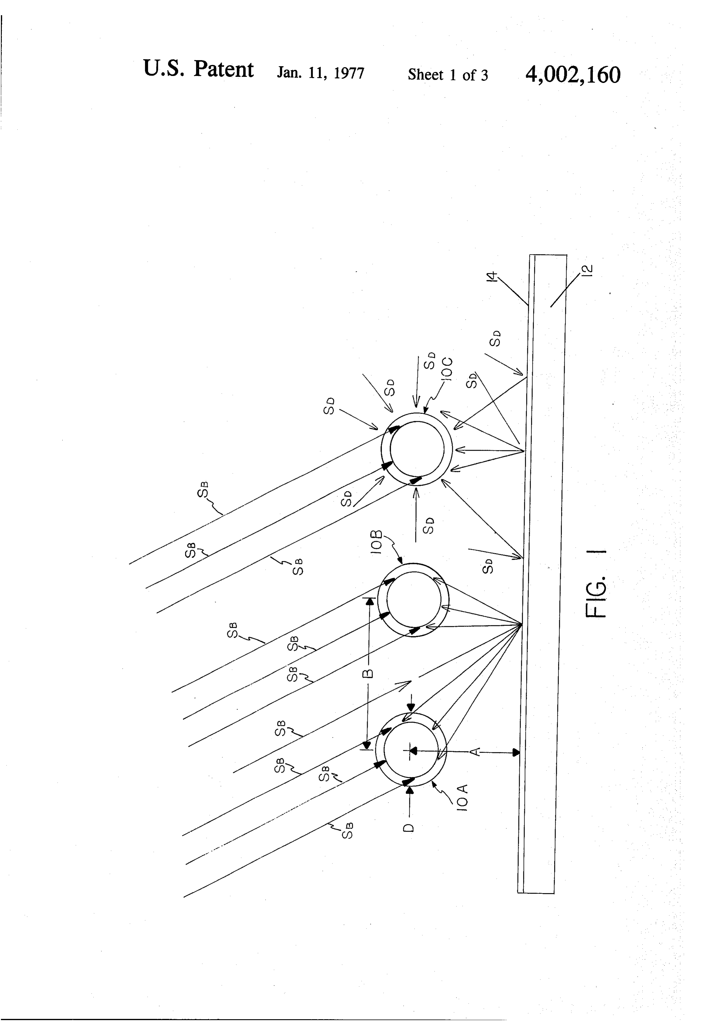
BACKGROUND OF THE INVENTION This component is not collimated and the rays are not This invention generally relates to solar energy col 5 parallel, but rather this component is available at a lectors. More particularly, this invention relates to a surface from many directions. In the case of a flat plate solar energy collector of the type using an array of collector, the major energy absorption takes place at tubular collector elements. Specifically, this invention the time when the beam Sn is overhead or at Solar noon. relates to such a solar energy collector which has a At this time, there is no loss of available energy to a flat specific relationship of tube spacing to tube diameter O surface as a result of the beam St being inclined due to and of tube distance from a diffusely-reflecting surface. diurnal effects as shown in FIG. 1. Throughout the day, The use of tubular collector arrays for the collection the beam S. moves in response to the relative motion of of solar energy is known in the art. See, for example, the sun. Particularly during the winter in areas away U.S. Pat. Nos. 980,505 and 2,133,649. I have found from the equator, the sun's position is lower in the sky that a diffuse-reflecting surface positioned behind a 5 thus making the angle at which the beam Sh strikes a tubular solar energy collector array can significantly horizontal flat surface lower thereby causing loss in increase the efficiency. See U.S. Pat. No. 2,213,894 for energy available to a horizontal flat surface as a result an example of a diffuse reflector in the prior art. I have of the angular incident of the beam SB. This problem further found that if the tubes are spaced no farther may be solved to some extent by inclining a flat collec apart than four tube diameters on centers and no more 20 tor array to compensate for the sun's elevation. Despite than four tube diameters away from the diffuse-reflect this deficiency, for a given area covered with a solar ing surface, that maximum efficiencies may be energy-absorbing array, the flat plate allows the maxi achieved. mum availability of energy for absorption as versus an SUMMARY OF THE INVENTION array of tubular collectors. However, arrays of tubular 25 collectors offer significant advantages in that such an
My invention is a solar energy collector. This collec array is capable of operating at a higher output temper tor includes a manifold. The invention also includes a ature than is the flat plate type collector and in that the plurality of double-wall tubular members. The space weight and expense of a tubular array may be some between the walls is sealed at a sub-atmospheric pres what less than a flat plate collector. In addition, as sure. The tubular members each have a closed end 30 should be obvious from FIG. , the collection charac remote from the manifold and an open end in sealing teristics of a tubular array are somewhat independent engagement with the manifold. The outer wall of the of the actual position of the sun, since as the sun moves, edouble-wall tubular members is a transparent glass across the sky the sides and backs of the array may material which is transparent about its entire circum collect energy at one time of the day while the upper ference. The double-wall tubular members are all. 35 portion of it may collect energy during another part of spaced apart on centers no more than four times the the day. At all times, the direct beam SR which im diameter of the double-wall tubular members. A means pinges upon a cylindrical collector sees a constant in is provided for supplying a fluid media from the mani tercept area thus allowing maximum transfer of the fold to the interior of the plurality of tubular memberssolar energy. Despite this advantage, when solar collec and for returning the fluid media to the manifold. A 40 tors are made in a tubular array, shadowing effects can diffuse-reflecting surface is positioned on the side of occur from adjacent collectors when the sun is low on the tubular members away from the sun, the diffuse the horizon thus reducing the efficiency and overall reflecting surface being co-extensive with all of the energy-absorption properties of such an array. In FIG. tubular members. The diffuse-reflecting surface is posi 1, a plurality of tubular collectors 10A-10C are shown tioned no more than four times the diameter of the 45 as receiving solar energy. The tubular collectors are tubular members away from the center line of the tubu shown in greater detail in FIG. 2 and will be discussed lar members. with respect to FIG. 2. Suffice it to say at the moment that the tubular collectors 10A-10C can absorb solar
BRIEF DESCRIPTION OF THE DRAWINGS energy with the use of a heat transfer media and trans FIG. 1 is a schematic side elevational view of a tubu 50 mit this energy to a location for use in space heating lar solar collector illustrating the present invention and and cooling of a building, water heating for domestic its operational principles, purposes or for powering solar cngines. In order to FIG. 2 is a perspective view, partially cut away, illus increase the efficiency of the tubular array, a back trating one embodiment of the present invention; plate 12 is positioned behind the tubular collectors FIG. 3 is a chart of efficiency versus tube to tube 55 10A-10C. The back plate 12 has its surface that faces spacing for a series of inlet fluid temperatures; and the tubular collectors 10A-10C coated with a diffuse FIG. 4 is a chart of efficiency versus tube distance reflecting material, such as white paint. This is a very from the diffusely-reflecting surface for a series of inlet thin layer and is exaggerated in FIG. 1 for purposes of fluid temperatures. illustration. Reflecting surfaces behind solar collector 60 arrays are known in the art. However, these surfaces
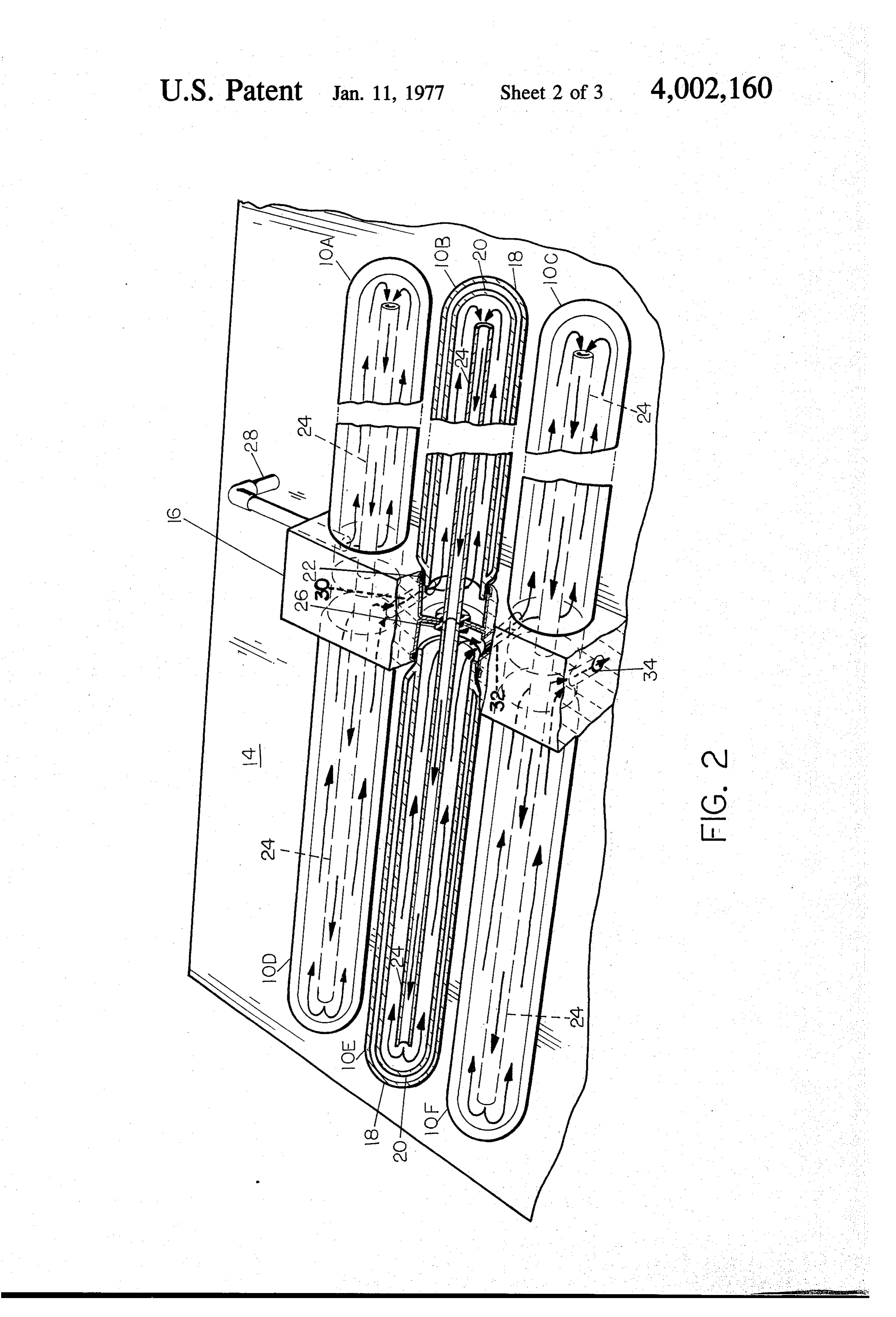
DETAILED DESCRIPTION OF THE DRAWENGS have normally been polished surfaces, and even more FIG. 1 illustrates in a very schematic fashion the frequently have been focusing surfaces which at basic principles upon which the present invention oper tempted to focus those direct beams Sn which missed a ates. As is well known, solar radiation is made up of two collector back to the collector. Polished surfaces and primary components. There is a component designated 65 focusing surfaces suffer from fabrication difficulties as Sr which is incident upon the surface of the earth which raise the expense of a solar collector array. In from the position of the sun at any given time. The addition, exposure to the elements for a period of time component St is a collimated beam of light, in FIG. 1 causes polished surfaces to generally lose their polished 6 sheen and would, therefore, cause focused-type sur opening in the manifold 16 in a gasket 22. Note that faces to lose the precision of focus which is necessary while the inner tube 20 is shown as sealed in the mani for most efficient operation of such collector arrays. It fold 16, in practice either the outer tube 18 or the inner is well known to place a single tubular collector at the tube 20 could be sealed in the manifold 16. In most focal point of a parabolic reflector. However, as general terms, the tubes 18 and 20 form a doublewall pointed out, over a period of time such a reflector tubular member with a closed end remote from the would begin to dull and lose its initial effective reflect manifold 16 and an open end in sealing engagement ing properties. In addition, such an array requires that with the manifold 16. A cross-connecting tube 24 ex the focusing parabola track the position of the sun to tends from a position adjacent the closed end of the ensure that maximum energy is imparted to the tubular O inner tube 20 of the collector 10B to a position adja collector. There are also known low concentration cent the closed end of the inner tube 20 of the collector parabolic collectors which do not require tracking, but 10.E. The collectors 10B and 10E are in communica these do not collect the maximum available energy. My tion only through the cross-connecting tube 24, and the invention utilizes a tubular array of solar collectors cross-connecting tube 24 is mounted in a gasket 26 10A-10C which need not be moved in order to absorb 15 within the manifold 16 to ensure that the only path maximum solar energy. A diffuse-reflecting layer 14 on available for fluid travel is along or through the cross the back plate 12 reflects back any collimated beams connecting tube 24. The cross-connecting tube 24 may S or diffuse beams St, which impact upon it in a diffuse be either a glass or a metal tube material. The working pattern as seen in FIG. I. There is no attempt made to fluid to be heated by solar energy enters the manifold focus the reflection of any beams of light which are through an inlet line 28. The fluid is first directed along incident upon the layer 14 to any particular one of the the length of the tubular collector 10A around the tubular collectors 10A-10C. Rather, there is a random outside of the cross-connecting tube 24 which connects back reflection of light incident upon the layer 14 to all the tubular collectors 10A and 10B. The fluid flows of the tubular collectors 10A-10C which are posi down the length of the cross-connecting tube 24 and tioned above the back plate 12. The tubular collectors 25 into the tubular collector 10D. During this passage and 10A-10C are positioned a distance A above the diffuse during the time it is in the collector 10A the fluid has layer 14. The distance A may usually be defined in been heated by extracting energy from the absorber terms of the outside or overall diameter D of the tubu surface. As the fluid reaches the open end of the tubu lar collectors 10. Likewise, the tubular collectors 10 lar collector 10D and enters the manifold, a cross-con themselves have a center line spacing which is gener 30 necting passage 30 formed in the manifold 16 directs ally designated as B. There are a set of relationships the fluid into the open end of the tubular collector 10B. which inter-relate the distances A and B with the diam The fluid then flows along the length of the tube 10B eter of the tubes D to achieve maximum energy-absorp and along the cross-connecting tube 24 which connects tion from a tubular collector array. These relationships the tubes 10B and 10E and enters the cross-connecting will be discussed later. 35 tube 24 at the closed end of the tubular collector 10B. FIG. 2 illustrates one type of tubular collector array Fluid flows down the length of the tube 24 and into the to demonstrate practical application of my invention. tubular collector 10E. The fluid then passes back along The tubular collector array shows six tubular collectors the length of the tubular collector 10E and once again 10A through 10F. The tubular collectors 10 are enters the manifold 16. A second cross-connecting mounted on each side of a manifold 16. In FIG. 2, the 40 passage 32 directs the fluid into the open end of the manifold 16 is positioned transversely to the pitch of a tubular collector 10C. The path of the fluid is identical roof, which includes the diffusely-reflecting surface 14, for that previously described with respect to the collec on which the collector array would be mounted. Thus, tors 10A, 10B, 10D and 10E with respect to the collec the tubes OD, 10E and 10F would be “down' relative tors 10C and 10F. That is, the fluid goes down the to the tubes 10A, 10B and 10C. This relationship is 45 length to the collector 10C, enters the cross-connecting important if the working fluid is a liquid to prevent air tube 24, exits into the collector 10F and then flows locks and to allow the use of gravity flow whenever back into the manifold 16. The fluid coming from the possible to keep pumping pressures low. All of the tubular collector 10F may be utilized at this point for tubular collectors 10A through 10F are identical in its energy content by removing it from the manifold 16 construction and the collectors 10B and 10E have been 50 through a passage 34. If desired, however, the working shown completely in cross section in order to explain fluid may be passed through still further tubular collec the structure of the collectors. An outer transparent tors and additional solar energy collected before the glass tube 18 has one closed end which extends beyond fluid is utilized. The example of FIG. 2 is simply one the manifold 16 and an open end which is adjacent to form of tubular collector which may be used to obtain the manifold 16. The tube 18 is completely transparent 55 significant solar energy. A system which uses parallel around its entire circumference to allow maximum flow as opposed to the series flow shown in FIG. 2, collection of solar radiation. This differs from such could also be successfully utilized. The major parame tubes in the prior art which were generally at least ters are that the spacing of the tubular collectors 10A partially mirrored or coated in some manner. An inner through 10F be properly selected and that the diffuse tube 20 is sealed to the outer tube 18 near the open end 60 layer 14 reflect light back to the tubular collectors 10A of the outer tube 18. The inner tube 20 may be glass, through 10F in a diffuse manner rather than in a specu but also could be a metal tube. The inner tube 20 may lar manner, keeping in mind factors such as (l) best be blackened or provided with an overall selectively back-reflecting properties; (2) best use of incident absorbing coating to absorb the solar energy. The space diffuse light; and (3) best symmetry effect for direct between the tubes 18 and 20 is evacuated or reduced to 65 light.
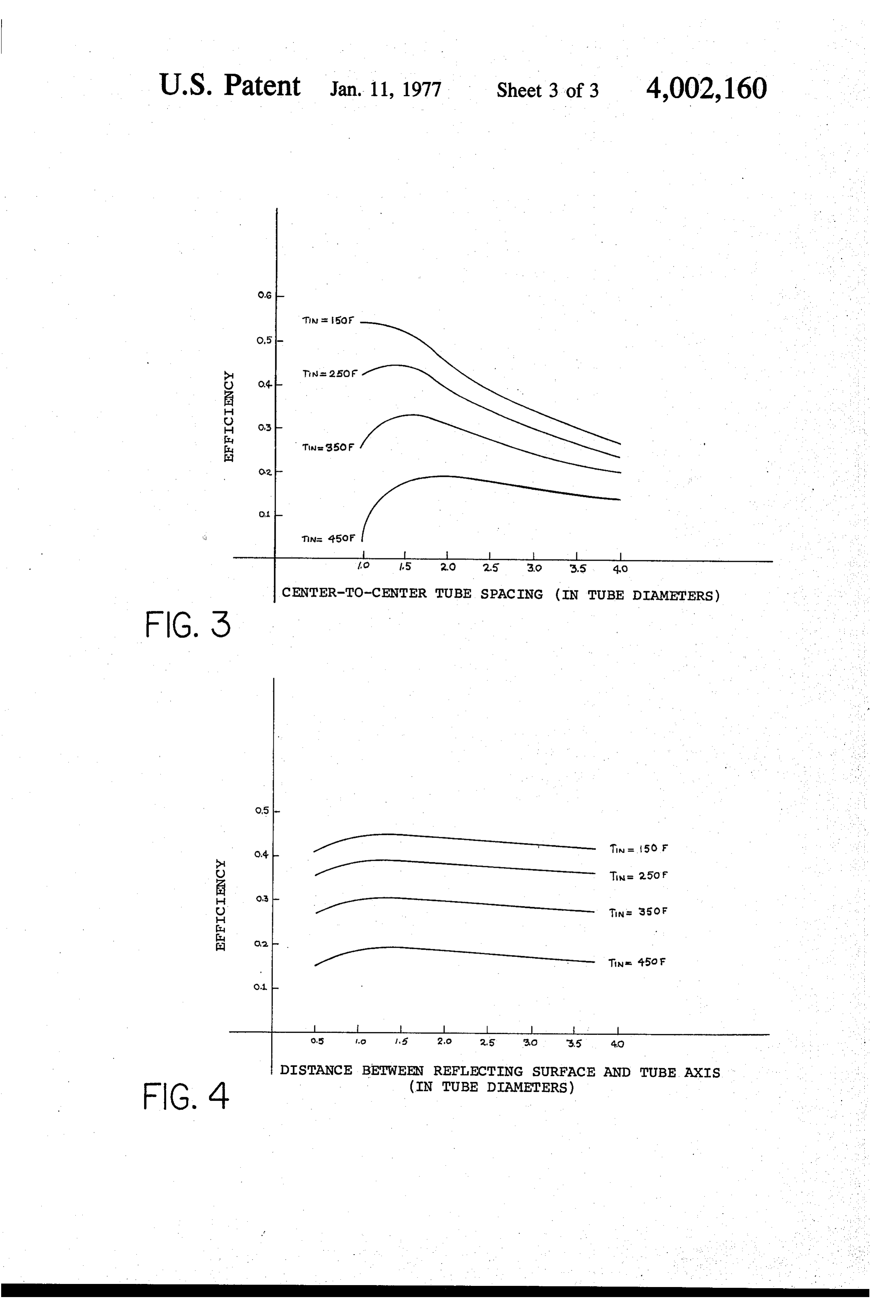
subatmospheric pressure to reduce conduction and FIGS. 3 and 4 are charts showing performance data convection losses from the collector. The open end of for a multiple tube solar energy collector such as that the inner tube 20 is in sealing engagement with an illustrated in FIG. 2. A diffuse-reflecting layer 14 was
Page 7scan →
S 6 used behind the solar energy collector array in all mote from said manifold and an open end in sealing cases. FIGS. 3 and 4 illustrate that there is a preferred engagement with said manifold, the outer wall of range of spacings of the tubes from one another and said double-wall member being a transparent glass from the diffuse-reflecting surface 14. All of the data in material and is transparent about its entire circum FIGS. 3 and 4 were taken at an ambient temperature of ference, said double-wall tubular members being 77 F. and at solar noon. In addition, the data in FIGS. spaced apart on centers no more than four times : 3 and 4 do not include any component from diffuse the diameter of said tubular members; sunlight. Thus the actual curves shown in FIGS. 3 and means for supplying a working fluid from said mani 4 would be shifted somewhat to the right of the axis fold to the interior of said plurality of tubular mem shown in FIGS. 3 and 4 if the diffuse component were 10 bers and returning said working fluid to said mani added. In addition, the symmetry factor is likewise not fold; and included in FIGS. 3 and 4. The symmetry factor of a a diffuse-reflecting surface positioned on the side of multiple tube array becomes more important with in said tubular members away from the sun and being creased tube spacing and would also have a tendency to coextensive with all of said tubular members, said shift the total curves somewhat to the right. However, 15 diffuse-reflecting surface being positioned a dis the curves illustrated in FIGS. 3 and 4 are sufficient to tance no more than four times the diameter of said clearly demonstrate that there is indeed a preferred tubular members away from the center line of said range for tube spacing both one to another and from tubular members.
the diffuse back-reflecting surface 14. In FIG. 3, a 2. The solar energy collector of claim 1 which further series of curves are shown for various inlet working 20 includes:
fluid temperatures. In FIG. 3, the distance of the tubu an energy-absorbing, opaque coating covering sub lar array from the back-reflecting surface 14 was re stantially an entire surface of the inner walls of tained constant at a spacing of about one and one-half each one of said double-wall tubular members. tube diameters. Note that as the center to center tube 3. The solar energy collector of claim 1 wherein said spacing, as expressed in tube diameters, increases, the 25 means for supplying a working fluid includes: efficiency of the collector rises, reaches a maximum a plurality of tubes, communicating with said mani and then begins to decrease. This is true in all cases fold, extending in coaxial relationship within the except for the low temperature case of 150' F. inlet interior of each of said plurality tubular members temperature. This effect becomes more marked as the to a location adjacent the closed ends of said tubu inlet temperature of the working fluid increases. It is 30 lar members.
therefore clear that there is a peak efficiency reached 4. The solar energy collector of claim 3 wherein said somewhere between 1.5 and 2 tube diameters spacing. plurality of tubes are comprised of glass. However, as was previously noted, symmetry effects 5. A solar energy collector for a building with an and diffuse radiation effects would dictate that this inclined roof structure which comprises, in combina value be shifted somewhat to a range of about 2 to 2.5. 35 tion:
tube diameters for preferred spacing. The range actu a manifold mounted on said roof structure trans ally extends outward until about four tube diameters versely to said roof structure; which is considered to be the maximum tube center to a first plurality of double-wall tubular members, the center tube spacing that would be practical and still space between said double walls being sealed at a allow significant collection of solar energy with a rea 40 sub-atmospheric pressure, each having a closed sonable size collector array. In FIG. 4, the test condi end remote from said manifold and an open end in tions were maintained the same as in FIG. 3. However, sealing engagement with the side of said manifold in FIG. 4 the spacing of the tubular array was held toward the peak of said roof structure, the outer constant at two tube diameters. The distance of the wall of said double-wall tubular member being a array above the diffuse-reflecting surface 14 was then 45 transparent glass material and being transparent varied as a function of the tube diameters. Again note about its entire circumference, said first plurality that there is a rise in efficiency to a maximum at about double-wall tubular members being spaced apart two tube diameters away from the diffuse-reflecting on centers no more than four times the diameter of surface with the efficiency then beginning to drop off said first plurality of tubular members; from that point. As was the case with the tube to tube 50 a second plurality of double-wall tubular members, spacing, the maximum practical spacing is believed to the space between said double walls being sealed at be about four tube diameters away from the diffuse a sub-atmospheric pressure, each having a closed reflecting surface 14. Under some conditions, the en end remote from said manifold and an open end in tire tubular array might be inclined with respect to the sealing engagement with the side of said manifold surface upon which it is mounted. In this case, the 55 toward the ground, the outer wall of said double uppermost portion of the tubular collectors could be wall tubular members being a transparent glass more than four tube diameters away from the diffuse material and being transparent about its entire reflecting surface. However, the average spacing of the circumference, said second plurality of double-wall entire length should still be kept to within four tube tubular members being spaced apart on centers no diameters. The total energy flux represented by FIGS. 3 60 more than four times the diameter of said second and 4 is about 300 B.T.U.'s per hour per square foot plurality of tubular members; which is approximately 1.1 Langleys per minute. means for supplying a working fluid from said mani What I claim is: fold to the interior of said first and second plurality 1. A solar energy collector which comprises: of tubular members and returning said working a manifold; 65 fluid to said manifold; and a plurality of double-wall tubular members, the space a diffuse-reflecting surface on said roof structure between said double walls being sealed at a subat below said manifold and said first and second plu mospheric pressure, each having a closed end re rality of tubular members, said diffuse-reflecting 8 surface being co-extensive with all of said tubular each one of said first and second plurality of tubu members and being positioned a distance no more lar members.
than four times the diameter of said first or second 7. The solar energy collector of claim 5 wherein said plurality of tubular members away from the center means for supplying a working fluid includes: line of said first and second plurality of tubular 5 a plurality of tubes, communicating with said mani members. fold, extending in coaxial relationship within the 6. The solar energy collector of claim 5 which further : interior of each of said first and second plurality of includes: - tubular members to a location adjacent the closed an energy-absorbing, opaque coating covering sub- ends of said tubular members. stantially an entire surface of the inner walls of 10 . sk + k.* *
Provenance
- Collection
- Patents citing this work
- Pages
- 8
- Method
- pdftotext (the PDF's own text layer) + pdftoppm 300dpi page scans
- Patent office record
- patents.google.com →
- Source
- Google Patents citing-documents table
- Assignee
- Owens-Illinois, Inc.
- Published
- 1977-01-11
- Transcribed from
- patentimages.storage.googleapis.com →