

patent · US4011840A
Drive system for a motor vehicle
15 March 1977
Text
Page 1bibliographic recordscan →
Forster
54 DRIVE SYSTEM FOR A MOTOR VEHICLE
(75) Inventor: Hans-Joachim M. Forster, Stuttgart,
Germany 73 Assignee: Daimler-Benz Aktiengesellschaft,
Germany
30 Foreign Application Priority Data
52 U.S. Cl. ............................ 123/3; 123/DIG. 12;
51 Int. Cl. ......................................... F02B 43/08
UNITED STATES PATENTS
3,608,660 9/971 Smith ............................ 231. A X 3,616,779 l if 197 Newkirk ..................... 123/DIG. 12 3,635,200 lf 1972 Rundell et al. ........................ 123/3 3,682, 42 8/1972 Ncwkirk ........................ 12311 A X 3,688,755 9/1972 Grayson et al. ............ 1231. A UX
3,732,690 5/1973 Meyer ........................... 123/ | A X 3,818,875 6/1974 Phillips et al. ................. 23/ A X 3,890,946 6/1975 Wahl ............................. 1231. A X 3,897,757 8/1975 Abello ........................ 123/DIG. 12
Primary Examiner-Charles J. Myhre
Assistant Examiner-Ira S. Lazarus
Attorney, Agent, or Firm-Craig & Antonelli
A drive for a motor vehicle with an internal combustion engine which is fed from a fuel tank with a fossil fuel by way of a fuel line; the fuel tank is thereby also con nected with a cracking carburetor from which a line leads to a hydride storage device which, in turn, is connected with the internal combustion engine; the internal combustion engine can be operated with pure hydrogen or with a hydrogen-fuel-gas mixture in high density traffic areas as well as with a large excess of air whereas it can be operated on open highways, after shifting, with a conventional fossil fuel and with an air ratio number of about 1.
26 Claims, 1 Drawing Figure
Drawings
Page 2drawing sheetscan →
Page 3scan →
Drive system for a motor vehicle
The present invention relates to a drive for a motor vehicle with an internal combustion engine, which is supplied with a fossil fuel from a fuel tank by way of a fuel line.
It is known in principle that an internal combustion engine can be operated with hydrogen or with another mixture enriched with hydrogen. A combustion engine whose combustion gas has a high hydrogen proportion, can be leaned down extremely so that, on the one hand, only disappearingly small CO-, HC- and NO concentrations are present in the exhaust gas and si multaneously a better efficiency of the engine can be achicved in the transition to a quality control. It is also known that increased hydrogen proportions in the combustion gas permit a larger excess of air and therewith a decrease of the harmful substance emis sion. In relation to carbon monoxide and nitrogen ox ides, it is possible to stay below the most strict, hereto fore provided limit values. However, the emission val ues of the hydrocarbons cannot be kept as low as one would like to by such measures.
It is further known that with pure hydrogen operation no carbon monoxides and no hydrocarbons are emitted and that it offers no difficulty to keep extremely low the proportions of the nitrogen oxides. However, it is still open in that connection how the hydrogen can be made ready and available in larger quantities and at different places to a sufficient extent.
It is additionally known that fuel can be gasified in cracking carburetors with or without catalysts. In the gasoline cracking, which is carried out for the most part with catalytic agents, hydrocarbons can be decom posed into its gaseous components, namely CH, H2 but also into higher hydrocarbons and into CO together with CO. However, a considerable expenditure has to be undertaken for the complete, economically accept able gasification.
Finally, it is also known that promising hydrogen tanks can be represented by metal hydrides of suitable compositions. Metal compounds are able to store hy drogen by the formation of metal hydrides and are able to selectively absorb also hydrogen out of gas mixtures. However, for purposes of filling these tanks or hydro gen storage devices, a suitable infra-structure is still required which will certainly not be available for some longer periods of time.
It is the aim of the present invention to provide a self-sufficient drive for a motor vehicle, i.e., indepen dent of “hydrogen tanking places", which is still eco nomical to an acceptable extent and falls below the strictest safety limits to be expected in areas of high traffic density where bumper traffic and/or traffic tie ups occur, and which additionally permits an economic driving of the motor vehicle in a known manner and with known means, namely with fossil fuels. The fossil fuels thereby should also serve as basic substance for the production of the fuels to be used in high density traffic areas.
The underlying problems are solved according to the present invention in that the fuel tank is additionally connected with a cracking carburetor or any conven tional construction, from which a line leads to a hy dride storage devicc which in turn is connected with the internal combustion engine which can be operated with hydrogen or with a hydrogen-fuel-gas mixture as well as with a high excess of air in high-density traffic or jam-up areas and which, after shifting, can be operated with a fossil fuel and a value of A of about 1 on open highways.
Such a drive system is able to get along with the present-day fuel supply but can be converted later on also without difficulty to a supply of fuel with hydro gen. With this drive system, the type of combustion and the combustion mixture may always be so selected as is () necessary in order to realize the required emission. In traffic jam or high density traffic areas, one will drive only with hydrogen, in suburbs one will shift to a hydro gen-gasoline-gas mixture operation, and on open high ways, one will drive with fossil fuel as under classic 15 operation. During the operation with hydrogen, it is therefore possible to drive with a high excess of air in order to lower the emission of harmful exhaust gas components and simultaneously also the fuel consump tion, especially during mixture operation. This is So as 20 one has started heretofore with the concept that the hydrogen necessary for the operation has to be tanked in some distributor network. Since it will probably be still some time until the technology of a hydrogen Sup ply system is developed and the infra-structure neces sary therefor has been worked out, the present inven tion provides with the presently existing infra-structure a drive system which does not require a hydrogen dis tribution network because in the present invention the necessary hydrogen is produced in the vehicle itself. According to a further feature of the present inven tion, one valve each may be arranged in the line con necting the fuel tank with the engine and in the line connecting the cracking carburetor with the hydride storage device which are opened and closed at the same time and in the same sense. The closing of the valve in the line which connects the gasoline tank with the engine may thereby take place only to a certain degree so that this valve still remains open slightly with 40 the closing of the other valve so that in addition to the hydrogen, a small quantity of fossil fuel is also supplied to the engine with a high excess of air. If one drives completely with pure hydrogen, then corresponding constructive changes of the engine are required. 45 As to the rest, a water tank may also be provided which is connected with the cracking carburetor. Con sequently, the carburetor may be operated with the addition of air or water or with the addition of both air and water. If the cracking carburetor is operated only 50 with air, then about 50% nitrogen, and 5% CO, and about 15% of each of CO, H. and CH will then result. If in contradistinction thereto, the cracking carburetor, in addition to being operated with gasoline, is operated only with water, then no nitrogen results, whereas 55 about 70% of H and about 10% each of CO, CO and CH will be produced. With a mixture operation by the addition of air and water, these values change corre spondingly to the admixed quantity ratios of air and Water.
60 The hydride storage device may also be provided with a heating system, by means of which the yield or output of the hydrogen can be stimulated during the beginning of the shifting to hydrogen operation. On the other hand, the hydride storage device may be cooled 65 in order to favor the absorption of hydrogen. The advantage of the present invention resides in that all advantages can be realized with the same which offers a pure hydrogen operation or an operation in 4 which hydrogen is used in part, without being relegated lineThe12cracking carburetor 5 is connected by way of the with a hydride storage device 13 of conven to a hydrogen infra-structure. ,y
Accordingly, it is an object of the present invention tional type. This hydride storage device 13 is able to conduct to the engine 1 by way of the line 14, hydrogen to provide a drive for a motor vehicle which avoids by previously simple means the aforementioned shortcomings and 5 carburetor stored and/or other gases resulting in the drawbacks encountered in the prior art. 5 during the cracking of the fuel. Another object of the present invention resides in an The lines 2, 4 and 12 are provided with valves 15, 16 internal combustion engine for a motor vehicle capable and 17, respectively, whose operating levers are con nected with each other by a linkage 18 so that they can of operation with hydrogen as fuel which offers an () be economically acceptable operation without excessive mayopened be so and closed simultaneously. The valve 15 constructed that it is still slightly opened expenditures.
A further object of the present invention resides in a when the valves 16 and 17 are already closed. drive arrangement for a motor vehicle operable by the nerThe engine 1 can now be operated in the usual man use of hydrogen which does not require the availability 15 and with gasoline. For that purpose, the valves 15, 16 of hydrogen through an established distribution net fuel tank 3 opened.
not only
Fuel is thereby conducted from the by way of the line 2 to the engine work.
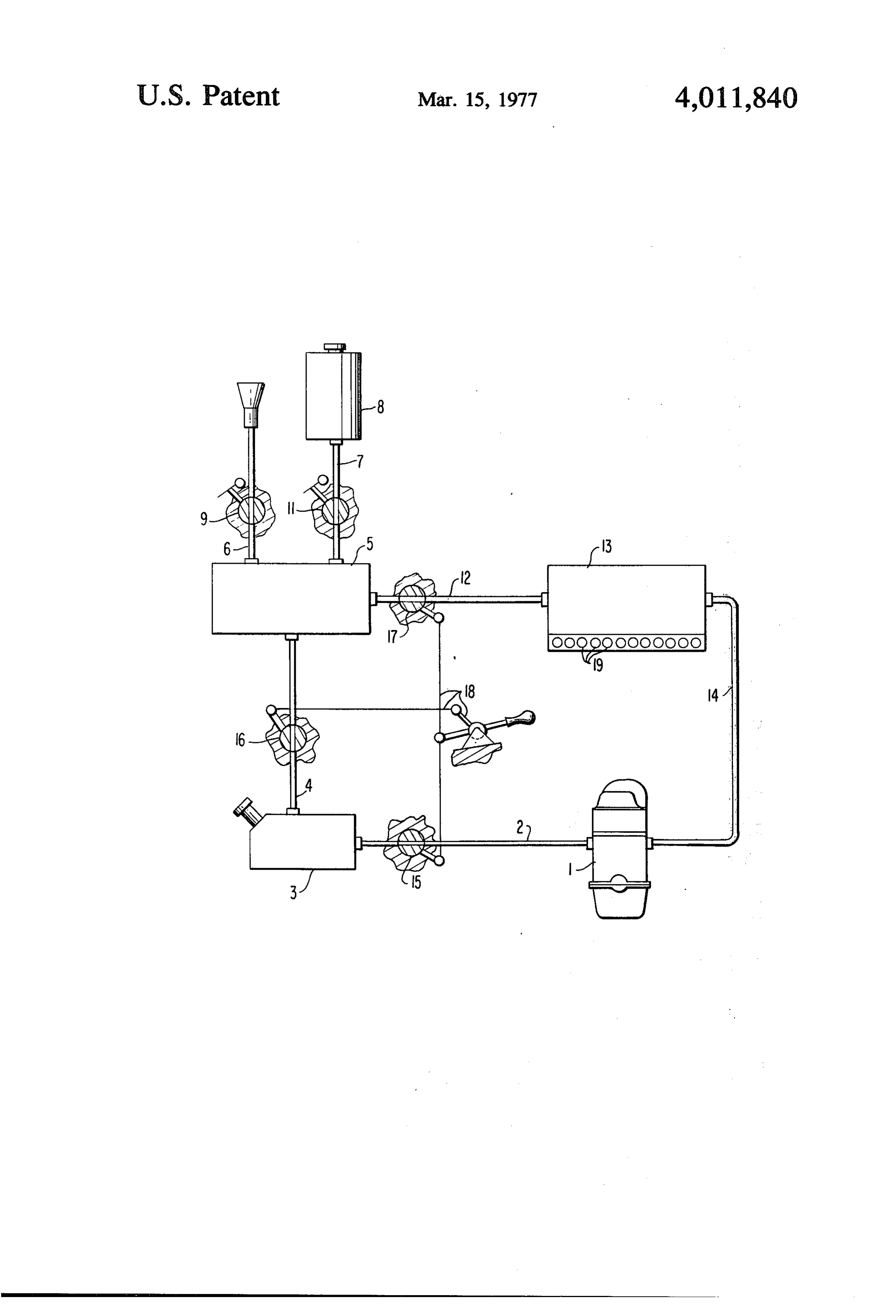
A still further object of the present invention resides tor 5. The fuel is crackedlinein 4theto cracking 1 but also by way of the the cracking carbure carburetor 5 in a drive for an internal combustion engine which is into gaseous components which are conducted by way completely sclf-sufficient insofar as the operation of 20 of the line 12 to the hydride storage device 13. The the engine with hydrogen as fuel is concerned. latter absorbs the hydrogen which is stored in the alloy Another object of the present invention resides in a drive for an internal combustion engine operable with disposed on the inside thereof. The remaining gas hydrogen which is economically feasible within accept tor 5 flowsalso which has been produced in the cracking carbure through the hydride storage device 13 and able expenditures and is capable of meeting all safety 25 will also be still conducted limits as regards exhaust contamination which are pres line 14 so that these gasestocan the engine 1 by way of the also be utilized in the ently expected. combustion engine 1. The composition of the gases A further object of the present invention resides in a cracked in the cracking carburetor 5 depends on drive for a motor vehicle which permits operation of whether the cracking carburetor is operated without the vehicle both with fossil fuels and hydrogen in an 30 water or with water out of the water tank 8. With a economically feasible manner. larger supply of water, the nitrogen content can be Still another object of the present invention resides in reduced to zero.
a drive for a motor vehicle with the use of hydrogen This manner of driving will preferably be selected on which is able to get along with the fuel supply system open highways whereby one will drive with an air ratio available at present. 35 number of about A = 1. The hydride storage device 13 A still further object of the present invention resides is thereby being charged. If one now approaches subur in a drive arrangement for an internal combustion en ban areas or high-density traffic areas, then one will gine of a motor vehicle in which the emission of harm shift by means of the lever linkage 18, either to a partial ful exhaust gas components can be lowered and the fuel removal of H out of the hydride storage device 13 or consumption can be improved. - 40 by completely closing the valves 15, 16 and 17, to a These and further objects, features and advantages of driving operation with pure hydrogen. One will thereby the present invention will become more apparent from operate with an air ratio number which lies considera the following description when taken in connection bly above 1 (M. may reach a value up to 2) whereby with the accompanying drawing which shows, for pur exhaust gases free of harmful substances can be poses of illustration only, one embodiment in accor 45 achieved.
dance with the present invention, and wherein: In order to stimulate the discharge of the hydride The single FIGURE is a schematic view of a drive storage device 13, the latter may be equipped with a arrangement for an internal combustion engine of a heater 19 of any conventional construction which may motor vehicle in accordance with the present, inven also be constructed for the reverse case as cooling tion. 50 installation, utilizing known principles for this purpose. Referring now to the single FIGURE of the drawing, While I have shown and described only one embodi a combustion engine 1 which may be a Diesel engine or ment in accordance with the present invention, it is an Otto engine is schematically illustrated therein to understood that the same is not limited thereto but is gether with the associated auxiliary means according to susceptible of numerous changes and modifications as the present invention. 55 known to those skilled in the art, and I therefore do not. The combustion engine 1 is connected by way of a wish to be limited to the details shown and described fuel line 2 with the fuel tank 3 which may contain either herein but intend to cover all such changes and modifi gasoline or Diesel fuel. Furthermore, the fuel tank 3 is cations as are encompassed by the scope of the ap connected by way of a line 4 with a conventional crack pended claims.
ing carburetor 5 of known construction, in which the 60 What is claimed is: w 1. A drive for a motor vehicle with an internal com hydrocarbons of the fuel are decomposed into gases components of CH, H, as well as into higher hydrocar bustion engine which is supplied with fossil fuels from a bons and CO. fuel tank by way of a fuel line, characterized in that the Air can be fed to the cracking carburetor 5 by way of 65 fuel tank is operatively connected also with a cracking carburetor means from which a line leads to a hydride the line 6 and water may be fed thereto out of a water storage tank 8 by way of the line 7. The lines 6 and 7 are pro with themeans which, in turn, is operatively connected combustion engine, the combustion engine vided with valves 9 and 11 which may be selectively opened or closed depending on the requirement. being operable in areas of high traffic density with at 5 least a hydrogen-fuel-gas mixture as well as with a high excess of air whereas, upon shifting over, it can be operated with fossil fuel and with an air ratio number of about on open highways.
2. A drive according to claim 1, characterized in that the combustion engine is selectively operable with hy drogen in areas of high traffic density.
3. A drive according to claim 1, characterized in that one valve means each is arranged in the line connecting the fuel tank with the engine and in the line connecting the cracking carburetor means with the hydride storage means, which are open and closed in the same direction and substantially at the same time.
4. A drive according to claim 3, characterized in that a water tank is provided which is operatively connectcd with the cracking carburetor means.
5. A drive arrangement according to claim 4, charac terized in that the hydride storage means is provided with a heater means.
6. A drive according to claim 5, characterized in that the hydride storage means is provided with a cooling
7. A drive according to claim 6, characterized in that the heater and cooling means are formcd by a revers ible heating and cooling system.
8. A drive according to claim 7, characterized in that the combustion engine is selectively operable with hy drogen in areas of high traffic density.
9. A drive according to claim 1, characterized in that a water tank is provided which is operatively connected with the cracking carburctor means.
10. A drive arrangement according to claim 1, char acterized in that the hydride storage means is provided with a heater means.
11. A drive according to claim 1, characterized in that the hydride storage means is provided with a cool ing means.
12. A drive arrangement according to claim 11, char acterized in that the hydridc storage means is provided with a heater means.
13. A drive arrangement for motor vehicles, the ar rangement comprising:
an internal combustion engine operable on hydrogen or fossil fuel, a fossil fuel tank means for accommodating a supply of fossil fuel, a fossil fuel line means for supplying fossil from said fossil fuel tank means to said internal combustion engine, a cracking carburetor means for decomposing hydro carbons of the fossil fuel into gaseous components, means for supplying air to said cracking carburctor mcans, means for communicating said fossil fuel tank means with said cracking carburetor means, a hydridc storage means for storing a supply of hy drogen, means for communicating said cracking carburetor means with said hydride storage means, means for communicating said hydride storage means with said internal combustion engine, and 5 means for selectively controlling said fuel line means and each of said communicating means such that the internal combustion engine is selectively opera ble on hydrogen alone, a hydrogen-fossil fuel mix ture, or fossil fuel alone.
() 14. An arrangement according to claim 13, further comprising a water tank means for accommodating a supply of water, and means for communicating said water tank means with said cracking carburctor means. 15. An arrangement according to claim 14, wherein the internal combustion engine when operated on fossil fuel alone operates with an air ratio number of about 1. 16. An arrangement according to claim 14, wherein means are provided for controlling the supply of air to said cracking carburetor means such that the internal combustion engine is operated with a high excess of air when operating on hydrogen alone.
17. An arrangement according to claim 14, wherein means are provided for controlling the air supplicd to the cracking carburetor means such that the internal 25 combustion engine is operated with a high excess of air when operating on a hydrogen-fossil fuel mixture. 18. An arrangement according to claim 13, wherein the internal combustion engine when operated on fossil fuel alone operates with an air ratio number of about l. 30 19. An arrangement according to claim 18, further comprising heater means for selectively heating the hydride storage means.
20. An arrangement according to claim 19, further comprising cooling means for selectively cooling the hydride storage means.
21. An arrangement according to claim 13, wherein means are provided for controlling the supply of air to said cracking carburetor means such that the internal combustion engine is operatcd with a high excess of air 40 when operating on hydrogen alone.
22. An arrangement according to claim 21, further comprising heater means for selectively heating the hydride storage means.
23. An arrangement according to claim 22, further 45 comprising cooling means for selectively cooling the hydridc storage means.
24. An arrangement according to claim 13, wherein means are provided for controlling the air supplied to the cracking carburetor means such that the internal combustion engine is operated with a high excess of air when operating on a hydrogen-fossil fuel mixture. 25. An arrangement according to claim 24, further comprising heater means for selectively heating the hydride storage means.
26. An arrangement according to claim 25, further comprising cooling means for selectively cooling the hydride storage means.
Provenance
- Collection
- Patents citing this work
- Pages
- 5
- Method
- pdftotext (the PDF's own text layer) + pdftoppm 300dpi page scans
- Patent office record
- patents.google.com →
- Source
- Google Patents citing-documents table
- Assignee
- Daimler-Benz Aktiengesellschaft
- Published
- 1977-03-15
- Transcribed from
- patentimages.storage.googleapis.com →